

Ä
²Low system voltage. If low system voltage is detected by the (CAB), the (CAB) will turn on the Amber Anti-Lock Warning Lamp until normal system voltage is achieved. Once normal voltage is seen at the (CAB), normal operation resumes.
²Low Brake Fluid. A low brake fluid condition will cause the Red Brake Warning Lamp to illuminate. When the fluid sensor again indicates an acceptable fluid level, the Red Brake Warning Lamp will go out. This condition may exist during hard cornering or while the vehicle is on a grade. If the vehicle is in motion above 3 M.P.H. the Amber Anti-Lock Warning Lamp will also be turned on.
²Low Accumulator Pressure. Low Accumulator Pressure will cause both the Red Brake Warning and Amber Anti-Lock Warning Lamps to illuminate. Once normal operating pressure is achieved, the lamps will extinguish and the system will return to normal operation.
Additionally, any condition that results in interruption of power to the (CAB) or hydraulic assembly may cause the Red Brake Warning and Amber Anti-Lock Warning Lamps to illuminate intermittently.
All the conditions (or faults) mentioned above, can store a fault code in the (CAB) module.
ABS BRAKE SYSTEM DIAGNOSTIC FEATURES
SYSTEM SELF DIAGNOSIS
The ABS system is equipped with a diagnostic capability that may be used to assist in isolation of ABS faults. The features of the diagnostics system are described below.
CONTROLLER ANTI-LOCK BRAKE (CAB)
Fault codes are kept in a Non-Volatile memory until either erased by the technician using the DRB II or erased automatically after 50 ignition cycles (key ONOFF cycles). The only fault that will not be erased after 50 (KEY CYCLES) is the (CAB) fault. The (CAB) fault can only be erased by using the DRB II diagnostic tester. More than one fault can be stored at a time. The number of key cycles since the most recent fault was stored is also displayed. Most functions of the (CAB) and (ABS) system can be accessed by the technician for testing and diagnostic purposes by using the DRB II Diagnostic Tester.
START-UP CYCLE
The START-UP CYCLE takes place immediately after the ignition switch is turned on. It is an electrical check of basic electrical functions such as the System Relay and Anti-Lock Warning Lamp Relay. During this check, the Amber Anti-Lock Warning Lamp is turned on, then turned off at the end of the test. The test takes approximately 1 - 2 seconds to complete.
ANTI-LOCK 10 BRAKE SYSTEM 5 - 91
DRIVE-OFF CYCLE
The DRIVE-OFF CYCLE takes place when the vehicle reaches about 3 miles per hour the first time after an ignition reset. During this test, the modulator solenoid valves are activated briefly to test their function. The DRIVE-OFF CYCLE will be bypassed if you drive-off with the service brake pedal depressed.
LATCHING VERSUS NON-LATCHING FAULTS
Some faults detected by the (CAB) are latching. The fault is latched and (ABS) function is disabled until the ignition switch is reset (turned OFF/ON). Thus (ABS) function is disabled even if the original fault has disappeared during the ignition cycle in which it occurred. Other faults are non-latching; any warning lights that are turned on are only on as long as the fault condition exists. As soon as the condition goes away. The Amber Anti-Lock Warning Light is turned off. Although a fault code will be set in most cases. (Example:low accumulator fault will not be stored for a time of 2 minutes after the fault is detected).
BENDIX ABS SYSTEMS DIAGNOSTICS
The Bendix Anti-Lock 10 Brake System diagnostics. Beyond the basic mechanical diagnostics, systems and components covered earlier in this section, is accomplished by using the DRB II diagnostic tester. See testing procedures outlined in the Bendix AntiLock 10 Diagnostics Manual for the 1992 M.Y.
Please reference the above mentioned manual. For any further diagnostic service procedures that are required on the Bendix Anti-Lock 10 Brake System, requiring the use of the DRB II diagnostic tester.
ON CAR HYDRAULIC ABS COMPONENT SERVICE
WARNING: FAILURE TO FULLY DE-PRESSURIZE THE HYDRAULIC ACCUMULATOR BEFORE PERFORMING HYDRAULIC SYSTEM SERVICE OPERATIONS. COULD RESULT IN INJURY TO SERVICE PERSONNEL AND OR DAMAGE TO PAINTED SURFACES. SEE SECTION 2 FOR ADDITIONAL WARNINGS AND CAUTIONS.
GENERAL SERVICE PRECAUTIONS
The following are general precautions that should be observed when servicing the Anti-Lock Brake System and/or other vehicle systems. Failure to observe these precautions may result in Anti-Lock brake system damage.
If welding work is to be performed on the vehicle, using an electric arc welder, the (CAB) connector should be disconnected during the welding operation.
5 - 92 ANTI-LOCK 10 BRAKE SYSTEM
The (CAB) or hydraulic assembly connector should never be connected or disconnected with the ignition switch in the ON position.
Many components of the Anti-Lock brake system are not serviceable and must be replaced as an assembly. Do not attempt to disassemble any component that is not designed to be a serviced component.
DE-PRESSURIZING HYDRAULIC ACCUMULATOR
The pump/motor assembly will keep the hydraulic accumulator charged to approximately 11,032 and 13,790 kPa (1600 and 2000 psi) any time that the ignition is in the ON position. The pump/motor assembly cannot run if the ignition is off or if either battery cable is disconnected.
Unless otherwise specified, the hydraulic accumulator should be de-pressurized before disassembling any portion of the hydraulic system. The following procedure should be used to relieve the pressure in the hydraulic accumulator:
(1)With ignition off, or either battery cable disconnected, pump the brake pedal a minimum of 40 times, using approximately 222 N (50 lbs.) pedal force. A noticeable change in pedal feel will occur, when the accumulator is discharged.
(2)When a definite increase in pedal effort is felt, pump pedal a few additional times. This will insure removal of all hydraulic pressure from the brake system.
CHECKING BRAKE FLUID LEVEL
CAUTION: Use only brake fluid conforming to DOT 3 specifications such as MoparT or Equivalent. Do not use any fluid in the brake hydraulic system, which contains a petroleum base. Do not use a container which has been used for petroleum based fluids or a container that is wet with water. Petroleum based fluids will cause swelling and distortion of rubber parts in the hydraulic brake system and water will mix with brake fluid, lowering the fluid boiling point. Keep all brake fluid containers tightly capped to prevent contamination.
The hydraulic assembly is equipped with a plastic fluid reservoir, with a filter/strainer located in the filler neck of each reservoir section.
The Anti-Lock brake system requires that the hydraulic accumulator be de-pressurized when checking the fluid level. To check the brake fluid level, the following procedure should be used:
(1) With the ignition off, de-pressurize the hydraulic accumulator by applying the brake pedal approximately 40 times, using a pedal force of approximately 220 N (50 lbs.). A noticeable change in pedal feel will occur when the accumulator is de-pressurized. When
Ä
a definite increase in pedal effort is felt, pump pedal a few additional times. This will insure removal of all hydraulic pressure from the brake system.
(2)Thoroughly clean both reservoir caps and surrounding area of reservoir before cap removal. This will avoid getting dirt into the reservoir and brake fluid.
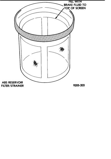
(3)Inspect the fluid level, see instructions on top of reservoir (Fill To Top Of The White Screen In Front Filter/Strainer).
(4)Fill reservoir to top of white screen on filter/strainer (Fig. 1) as required. Use only brake fluid conforming to DOT 3 specifications such as Mopart or an Equivalent.
Fig. 1 ABS Fill Level On Filter/Strainer
(5) Replace reservoir cap.
BLEEDING ABS BRAKE SYSTEM
The Anti-Lock brake system must be bled anytime air is permitted to enter the brake hydraulic system, due to disconnection of brake lines or hoses for service. It is important to note that excessive air in the brake system may set a primary pressure/delta P fault in the (CAB). Refer to Diagnosis, for further information.
Pressure bleeding or manual bleeding procedures can be used when bleeding the (ABS) hydraulic system, after brake lines or hoses have been disconnected. Bleeding the (ABS) hydraulic system is also necessary after the replacement of the hydraulic assembly or wheel brakes.
During bleeding operations, be sure that the brake fluid level remains close to the FULL level in the reservoir. Check the fluid level periodically during
Ä
the bleeding procedure and add only DOT 3 brake fluid to the reservoir as required.
PRESSURE BLEEDING (FIG. 2)
The brake lines may be pressure bled, using a standard diaphragm type pressure bleeder. Only diaphragm type pressure bleeding equipment should be used to prevent air, moisture, and other contaminants from entering the system. The following procedure should be used for pressure bleeding of the master cylinder and wheel circuits (Fig. 2).
(1)Ignition should be turned off and remain off throughout this procedure.
(2)De-pressurize the hydraulic accumulator by pumping the brake pedal a minimum of 40 times, as fully described in this section under De-Pressurizing Hydraulic Accumulator.
WARNING: FAILURE TO DE-PRESSURIZE HYDRAULIC ACCUMULATOR, BEFORE PERFORMING THIS OPERATION, MAY RESULT IN PERSONAL INJURY AND/OR DAMAGE TO PAINTED SURFACES.
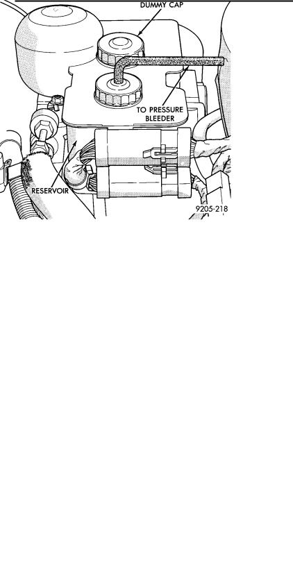
(3)Remove both reservoir caps (Fig. 2).
(4)Install pressure bleeder adapter, on front reservoir port and a cap on the rear port of the reservoir (Fig. 2).
(5)Attach bleeding equipment to bleeder adapter (Fig. 2). Charge pressure bleeder to approximately 138 kPa (20 psi).
Fig. 2 Pressure Bleeding Brake System
(6) Connect a transparent hose to the caliper bleed screw (Fig. 3). Submerge the free end of the hose in a clear glass container, which is partially filled with clean, fresh brake fluid.
ANTI-LOCK 10 BRAKE SYSTEM 5 - 93
(7)With the pressure bleeder turned on, open the caliper bleed screw 3/4 to one full turn allowing brake fluid to flow into the container. Leave bleed screw open until a clear, bubble-free flow of brake fluid is coming from the hose in the container. If the reservoir has been drained or the hydraulic assembly removed from the car before the bleeding operation. Slowly pump the brake pedal one or two times while the bleed screw is open and fluid is flowing. This will help
purge any trapped air from the hydraulic assembly. Tighten bleeder screw to 10 NIm (7.5 ft. lbs.) torque.
(8)Step 7 above should be done at all wheel brakes, following the order wheel by wheel as listed below.
a) Left rear. b) Right rear. c) Left front. d) Right front.
(9)After bleeding is completed at all four wheel brakes. Remove the pressure bleeding equipment and bleeder adapter by closing the pressure bleeder valve and slowly unscrewing the bleeder adapter from the hydraulic assembly reservoir. Failure to release pressure in the reservoir will cause spillage of brake fluid, and could result in personal injury or damage to painted surfaces.
(10)Using a syringe or equivalent method, remove excess fluid from the reservoir to bring the brake fluid to the required fill level (Fig. 1). If brake fluid is below the proper level add Mopart brake fluid or equivalent conforming to DOT 3, requirements.
(11)Install the reservoir caps and turn on the ignition to allow the (ABS) pump to charge the accumulator.
MANUAL BLEEDING
Brake lines can be bled, using the manual bleeding method. Manual bleeding is a two person operation, one to pump the brake pedal and the other to bleed each wheel brake. The following procedure should be used:
De-pressurizing the hydraulic accumulator is done by following the steps described below.
(1)Verify that the ignition switch is in the off posi-
tion.
(2)De-pressurize the hydraulic accumulator by pumping the brake pedal a minimum of 40 times. Use the procedure as described in De-Pressurizing Hydraulic Accumulator listed earlier in this section.
WARNING: FAILURE TO DE-PRESSURIZE HYDRAULIC ACCUMULATOR, PRIOR TO PERFORMING THIS OPERATION, MAY RESULT IN PERSONAL INJURY AND/OR DAMAGE TO PAINTED SURFACES.
(3) Connect a transparent hose to the bleed screw on the wheel cylinder or brake caliper that is to be
5 - 94 ANTI-LOCK 10 BRAKE SYSTEM |
|
Ä |
|
Fig. 3 Bleeding Brake System
bled (Fig. 3). Submerge the free end of the hose in a clear glass container, which is partially filled with clean, fresh brake fluid.
(4)Slowly pump the brake pedal several times, using full strokes of the pedal and allowing approximately five seconds between pedal strokes. After two or three strokes, continue to hold pressure on the pedal, keeping it at the bottom of its travel.
(5)With pressure on the pedal, open the bleed screw 3/4 to 1 full turn. Leave bleed screw open until fluid no longer flows from the hose. Tighten the bleed screw and release the pedal. Be sure that the bleed screw it tightened before brake pedal is released, or air may be drawn back into hydraulic system.
(6)Repeat Steps 3, 4 and 5 on each wheel brake, until clear, bubble-free fluid flows from the hose.
(7)Repeat the above sequence at each wheel brake, in the following order:
a) Left rear. b) Right rear. c) Left front. d) Right front.
(8)Fill the hydraulic assembly to the proper fill level (Fig. 1) using Mopart or equivalent brake fluid meeting DOT 3, requirements.
(9)Install both reservoir caps on reservoir.
(10)Turn the ignition switch to the RUN position to allow the Pump/Motor to turn on and recharge the accumulator.
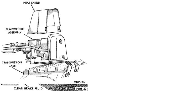
Fig. 4 Pump/Motor Assembly Mounting
PUMP/MOTOR SERVICE (FIG. 4)
REMOVE
(1) De-pressurize the hydraulic accumulator by pumping the brake pedal a minimum of 40 times. Using the procedure as described in De-Pressurizing Hydraulic Accumulator listed earlier in this section.
WARNING: FAILURE TO DE-PRESSURIZE HYDRAULIC ACCUMULATOR, BEFORE PERFORMING THIS OPERATION, MAY RESULT IN PERSONAL INJURY AND/OR DAMAGE TO PAINTED SURFACES.
(2)Remove the fresh air intake ducts from the engine induction system.
(3)Loosen the low pressure hose clamp (Fig. 5) at the hydraulic assembly.
(4)Disconnect any routing clips which attach the high and low pressure fluid lines to the body or components of the vehicle (Fig. 5).
(5)Unclip the pump/motor assembly wiring harness electrical connector from the left side engine mount (Fig. 5). Disconnect the pump/motor assembly wiring harness from the underhood wiring harness.
(6)Loosen the high pressure hose tube nut at the hydraulic assembly fitting (Fig. 5).
(7)Remove the high and low pressure hose assembly (Fig. 5) from the hydraulic assembly. Cap all open ports on reservoir and hydraulic assembly to prevent brake fluid from leaking out.
(8)Remove the pump/motor assembly front heat shield to mounting bracket attaching bolt, from front of pump/motor bracket (Fig. 5).
(9)Remove front heat shield from the pump/motor assembly.