

- •Foreword
- •Preface
- •Contents
- •About the Editors
- •Contributors
- •1: Tracheobronchial Anatomy
- •Trachea
- •Introduction
- •External Morphology
- •Internal Morphology
- •Mucous Layer
- •Blood Supply
- •Anatomo-Clinical Relationships
- •Bronchi
- •Main Bronchi
- •Bronchial Division
- •Left Main Bronchus (LMB)
- •Right Main Bronchus (RMB)
- •Blood Supply
- •References
- •2: Flexible Bronchoscopy
- •Introduction
- •History
- •Description
- •Indications and Contraindications
- •Absolute Contraindications
- •Procedure Preparation
- •Technique of FB Procedure
- •Complications of FB Procedure
- •Basic Diagnostic Procedures
- •Bronchoalveolar Lavage (BAL)
- •Transbronchial Lung Biopsy (TBLB)
- •Transbronchial Needle Aspiration (TBNA)
- •Bronchial Brushings
- •Advanced Diagnostic Bronchoscopy
- •EBUS-TBNA
- •Ultrathin Bronchoscopy
- •Transbronchial Lung Cryobiobsy (TBLC)
- •Therapeutic Procedures Via FB
- •LASER Bronchoscopy
- •Electrocautery
- •Argon Plasma Coagulation (APC)
- •Cryotherapy
- •Photodynamic Therapy
- •Airway Stent Placement
- •Endobronchial Valve Placement
- •Conclusion
- •References
- •History and Historical Perspective
- •Indications and Contraindications
- •Procedure Description
- •Procedure Planning
- •Target Approximation
- •Sampling
- •Complications
- •Future Directions
- •Summary and Recommendations
- •References
- •4: Rigid Broncoscopy
- •Innovations
- •Ancillary Equipment
- •Rigid Bronchoscopy Applications
- •Laser Bronchoscopy
- •Tracheobronchial Prosthesis
- •Transbronchial Needle Aspiration (TBNA)
- •Rigid Bronchoscope in Other Treatments for Bronchial Obstruction
- •Mechanical Debridement
- •Pediatric Rigid Bronchoscopy
- •Tracheobronchial Dilatation
- •Foreign Bodies Removal
- •Other Indications
- •Complications
- •The Procedure
- •Some Conclusions
- •References
- •History and Historical Perspective
- •Indications and Contraindications
- •Preprocedural Evaluation and Preparation
- •Physical Examination
- •Procedure-Related Indications
- •Application of the Technique
- •Topical Anesthesia
- •Anesthesia of the Nasal Mucosa and Nasopharynx
- •Anesthesia of the Mouth and Oropharynx
- •Superior Laryngeal Nerve Block
- •Recurrent Laryngeal Nerve Block (RLN)
- •Conscious Sedation
- •Monitored Anesthesia Care (MAC)
- •General Anesthesia
- •Monitoring the Depth of Anesthesia
- •Interventional Bronchoscopy Suites
- •Airway Devices
- •Laryngeal Mask Airway (LMA)
- •Endotracheal Tube (ETT)
- •Rigid Bronchoscope
- •Modes of Ventilation
- •Spontaneous Ventilation
- •Assisted Ventilation
- •Noninvasive Positive Pressure Ventilation (NIV)
- •Positive Pressure Controlled Mechanical Ventilation
- •Jet Ventilation
- •Electronic Mechanical Jet Ventilation
- •Postprocedure Care
- •Special Consideration
- •Anesthesia for Peripheral Diagnostic and Therapeutic Bronchoscopy
- •Anesthesia for Interventional Bronchoscopic Procedures During the COVID-19 Pandemic
- •Summary and Recommendations
- •Conclusion
- •References
- •Background
- •Curricular Structure and Delivery
- •What Is a Bronchoscopy Curriculum?
- •Tradition, Teaching Styles, and Beliefs
- •Using Assessment Tools to Guide the Educational Process
- •The Ethics of Teaching
- •When Learners Teach: The Journey from Novice to Mastery and Back Again
- •The Future Is Now
- •References
- •Interventional Procedure
- •Assessment of Flow–Volume Curve
- •Dyspnea
- •Analysis of Pressure–Pressure Curve
- •Conclusions
- •References
- •Introduction
- •Adaptations of the IP Department
- •Environmental Control
- •Personal Protective Equipment
- •Procedure Performance
- •Bronchoscopy in Intubated Patients
- •Other Procedures in IP Unit
- •References
- •Introduction
- •Safety
- •Patient Safety
- •Provider Safety
- •Patient Selection and Screening
- •Lung Cancer Diagnosis and Staging
- •Inpatients
- •COVID-19 Clearance
- •COVID Clearance: A Role for Bronchoscopy
- •Long COVID: A Role for Bronchoscopy
- •Preparing for the Next Pandemic
- •References
- •Historical Perspective
- •Indications and Contraindications
- •Evidence-Based Review
- •Summary and Recommendations
- •References
- •Introduction
- •Clinical Presentation
- •Diagnosis
- •Treatment
- •History and Historical Perspectives
- •Indications and Contraindications
- •Benign and Malignant Tumors
- •Tumors with Uncertain Prognosis
- •Application of the Technique
- •Evidence Based Review
- •Summary and Recommendations
- •References
- •12: Cryotherapy and Cryospray
- •Introduction
- •Historical Perspective
- •Equipment
- •Cryoadhesion
- •Indications
- •Cryorecanalization
- •Cryoadhesion and Foreign Body Removal
- •Cryoadhesion and Mucus Plugs/Blood Clot Retrieval
- •Endobronchial Cryobiopsy
- •Transbronchial Cryobiopsy for Lung Cancer
- •Safety Concerns and Contraindications
- •Cryoablation
- •Indications
- •Evidence
- •Safety Concerns and Contraindications
- •Cryospray
- •Indications
- •Evidence
- •Safety Concerns and Contraindications
- •Advantages of Cryotherapy
- •Limitations
- •Future Research Directions
- •References
- •13: Brachytherapy
- •History and Historical Perspective
- •Indications and Contraindications
- •Application of the Technique
- •Evidence-Based Review
- •Adjuvant Treatment
- •Palliative Treatment
- •Complications
- •Summary and Recommendations
- •References
- •14: Photodynamic Therapy
- •Introduction
- •Photosensitizers
- •First-Generation Photosensitizers
- •M-Tetrahidroxofenil Cloro (mTHPC) (Foscan®)
- •PDT Reaction
- •Tumor Damage Process
- •Procedure
- •Indications
- •Curative PDT Indications
- •Palliative PDT Indications
- •Contraindications
- •Rationale for Use in Early-Stage Lung Cancer
- •Rationale
- •PDT in Combination with Other Techniques for Advanced-Stage Non-small Cell Lung Cancer
- •Commentary
- •Complementary Endoscopic Methods for PDT Applications
- •New Perspectives
- •Other PDT Applications
- •Conclusions
- •References
- •15: Benign Airways Stenosis
- •Etiology
- •Congenital Tracheal Stenosis
- •Iatrogenic
- •Infectious
- •Idiopathic Tracheal Stenosis
- •Distal Bronchial Stenosis
- •Diagnosis Methods
- •Patient History
- •Imaging Techniques
- •Bronchoscopy
- •Pulmonary Function Test
- •Treatment
- •Endoscopic Treatment
- •Dilatation
- •Laser Therapy
- •Stents
- •How to Proceed
- •Stent Placement
- •Placing a Montgomery T Tube
- •The Rule of Twos for Benign Tracheal Stenosis (Fig. 15.23)
- •Surgery
- •Summary and Recommendations
- •References
- •16: Endobronchial Prostheses
- •Introduction
- •Indications
- •Extrinsic Compression
- •Intraluminal Obstruction
- •Stump Fistulas
- •Esophago-respiratory Fistulas (ERF)
- •Expiratory Central Airway Collapse
- •Physiologic Rationale for Airway Stent Insertion
- •Stent Selection Criteria
- •Stent-Related Complications
- •Granulation Tissue
- •Stent Fracture
- •Migration
- •Contraindications
- •Follow-Up and Patient Education
- •References
- •Introduction
- •Overdiagnosis
- •False Positives
- •Radiation
- •Risk of Complications
- •Lung Cancer Screening Around the World
- •Incidental Lung Nodules
- •Management of Lung Nodules
- •References
- •Introduction
- •Minimally Invasive Procedures
- •Mediastinoscopy
- •CT-Guided Transthoracic Biopsy
- •Fluoroscopy-Guided Transthoracic Biopsies
- •US-Guided Transthoracic Biopsy
- •Thoracentesis and Pleural Biopsy
- •Thoracentesis
- •Pleural Biopsy
- •Surgical or Medical Thoracoscopy
- •Image-Guided Pleural Biopsy
- •Closed Pleural Biopsy
- •Image-Guided Biopsies for Extrathoracic Metastases
- •Tissue Acquisition, Handling and Processing
- •Implications of Tissue Acquisition
- •Guideline Recommendations for Tissue Acquisition in Mediastinal Staging
- •Methods to Overcome Challenges in Tissue Acquisition and Genotyping
- •Rapid on-Site Evaluation (ROSE)
- •Sensitive Genotyping Assays
- •Liquid Biopsy
- •Summary, Recommendations and Highlights
- •References
- •History
- •Data Source and Methodology
- •Tumor Size
- •Involvement of the Main Bronchus
- •Atelectasis/Pneumonitis
- •Nodal Staging
- •Proposal for the Revision of Stage Groupings
- •Small Cell Lung Cancer (SCLC)
- •Discussion
- •Methodology
- •T Descriptors
- •N Descriptors
- •M Descriptors
- •Summary
- •References
- •Introduction
- •Historical Perspective
- •Fluoroscopy
- •Radial EBUS Mini Probe (rEBUS)
- •Ultrasound Bronchoscope (EBUS)
- •Virtual Bronchoscopy
- •Trans-Parenchymal Access
- •Cone Beam CT (CBCT)
- •Lung Vision
- •Sampling Instruments
- •Conclusions
- •References
- •History and Historical Perspective
- •Narrow Band Imaging (NBI)
- •Dual Red Imaging (DRI)
- •Endobronchial Ultrasound (EBUS)
- •Optical Coherence Tomography (OCT)
- •Indications and Contraindications
- •Confocal Laser Endomicroscopy and Endocytoscopy
- •Raman Spectrophotometry
- •Application of the Technique
- •Supplemental Technology for Diagnostic Bronchoscopy
- •Evidence-Based Review
- •Summary and Recommendations, Highlight of the Developments During the Last Three Years (2013 on)
- •References
- •Introduction
- •History and Historical Perspective
- •Endoscopic AF-OCT System
- •Preclinical Studies
- •Clinical Studies
- •Lung Cancer
- •Asthma
- •Airway and Lumen Calibration
- •Obstructive Sleep Apnea
- •Future Applications
- •Summary
- •References
- •23: Endobronchial Ultrasound
- •History and Historical Perspective
- •Equipment
- •Technique
- •Indication, Application, and Evidence
- •Convex Probe Ultrasound
- •Equipment
- •Technique
- •Indication, Application, and Evidence
- •CP-EBUS for Malignant Mediastinal or Hilar Adenopathy
- •CP-EBUS for the Staging of Non-small Cell Lung Cancer
- •CP-EBUS for Restaging NSCLC After Neoadjuvant Chemotherapy
- •Complications
- •Summary
- •References
- •Introduction
- •What Is Electromagnetic Navigation?
- •SuperDimension Navigation System (EMN-SD)
- •Computerized Tomography
- •Computer Interphase
- •The Edge Catheter: Extended Working Channel (EWC)
- •Procedural Steps
- •Planning
- •Detecting Anatomical Landmarks
- •Pathway Planning
- •Saving the Plan and Exiting
- •Registration
- •Real-Time Navigation
- •SPiN System Veran Medical Technologies (EMN-VM)
- •Procedure
- •Planning
- •Navigation
- •Biopsy
- •Complications
- •Limitations
- •Summary
- •References
- •Introduction
- •Image Acquisition
- •Hardware
- •Practical Considerations
- •Radiation Dose
- •Mobile CT Studies
- •Future Directions
- •Conclusion
- •References
- •26: Robotic Assisted Bronchoscopy
- •Historical Perspective
- •Evidence-Based Review
- •Diagnostic Yield
- •Monarch RAB
- •Ion Endoluminal Robotic System
- •Summary
- •References
- •History and Historical Perspective
- •Indications and Contraindications
- •General
- •Application of the Technique
- •Preoperative Care
- •Patient’s Position and Operative Field
- •Incision and Initial Dissection
- •Palpation
- •Biopsy
- •Control of Haemostasis and Closure
- •Postoperative Care
- •Complications
- •Technical Variants
- •Extended Cervical Mediastinoscopy
- •Mediastinoscopic Biopsy of Scalene Lymph Nodes
- •Inferior Mediastinoscopy
- •Mediastino-Thoracoscopy
- •Video-Assisted Mediastinoscopic Lymphadenectomy
- •Transcervical Extended Mediastinal Lymphadenectomy
- •Evidence-Based Review
- •Summary and Recommendations
- •References
- •Introduction
- •Case 1
- •Adrenal and Hepatic Metastases
- •Brain
- •Bone
- •Case 1 Continued
- •Biomarkers
- •Case 1 Concluded
- •Case 2
- •Chest X-Ray
- •Computerized Tomography
- •Positive Emission Tomography
- •Magnetic Resonance Imaging
- •Endobronchial Ultrasound with Transbronchial Needle Aspiration
- •Transthoracic Needle Aspiration
- •Transbronchial Needle Aspiration
- •Endoscopic Ultrasound with Needle Aspiration
- •Combined EUS-FNA and EBUS-TBNA
- •Case 2 Concluded
- •Case 3
- •Standard Cervical Mediastinoscopy
- •Extended Cervical Mediastinoscopy
- •Anterior Mediastinoscopy
- •Video-Assisted Thoracic Surgery
- •Case 3 Concluded
- •Case 4
- •Summary
- •References
- •29: Pleural Anatomy
- •Pleural Embryonic Development
- •Pleural Histology
- •Cytological Characteristics
- •Mesothelial Cells Functions
- •Pleural Space Defense Mechanism
- •Pleura Macroscopic Anatomy
- •Visceral Pleura (Pleura Visceralis or Pulmonalis)
- •Parietal Pleura (Pleura Parietalis)
- •Costal Parietal Pleura (Costalis)
- •Pleural Cavity (Cavitas Thoracis)
- •Pleural Apex or Superior Pleural Sinus [12–15]
- •Anterior Costal-Phrenic Sinus or Cardio-Phrenic Sinus
- •Posterior Costal-Phrenic Sinus
- •Cost-Diaphragmatic Sinus or Lateral Cost-Phrenic Sinus
- •Fissures18
- •Pleural Vascularization
- •Parietal Pleura Lymphatic Drainage
- •Visceral Pleura Lymphatic Drainage
- •Pleural Innervation
- •References
- •30: Chest Ultrasound
- •Introduction
- •The Technique
- •The Normal Thorax
- •Chest Wall Pathology
- •Pleural Pathology
- •Pleural Thickening
- •Pneumothorax
- •Pulmonary Pathology
- •Extrathoracic Lymph Nodes
- •COVID and Chest Ultrasound
- •Conclusions
- •References
- •Introduction
- •History of Chest Tubes
- •Overview of Chest Tubes
- •Contraindications for Chest Tube Placement
- •Chest Tube Procedural Technique
- •Special Considerations
- •Pneumothorax
- •Empyema
- •Hemothorax
- •Chest Tube Size Considerations
- •Pleural Drainage Systems
- •History of and Introduction to Indwelling Pleural Catheters
- •Indications and Contraindications for IPC Placement
- •Special Considerations
- •Non-expandable Lung
- •Chylothorax
- •Pleurodesis
- •Follow-Up and IPC Removal
- •IPC-Related Complications and Management
- •Competency and Training
- •Summary
- •References
- •32: Empyema Thoracis
- •Historical Perspectives
- •Incidence
- •Epidemiology
- •Pathogenesis
- •Clinical Presentation
- •Radiologic Evaluation
- •Biochemical Analysis
- •Microbiology
- •Non-operative Management
- •Prognostication
- •Surgical Management
- •Survivorship
- •Summary and Recommendations
- •References
- •Evaluation
- •Initial Intervention
- •Pleural Interventions for Recurrent Symptomatic MPE
- •Especial Circumstances
- •References
- •34: Medical Thoracoscopy
- •Introduction
- •Diagnostic Indications for Medical Thoracoscopy
- •Lung Cancer
- •Mesothelioma
- •Other Tumors
- •Tuberculosis
- •Therapeutic Indications
- •Pleurodesis of Pneumothorax
- •Thoracoscopic Drainage
- •Drug Delivery
- •Procedural Safety and Contraindications
- •Equipment
- •Procedure
- •Pre-procedural Preparations and Considerations
- •Procedural Technique [32]
- •Medical Thoracoscopy Versus VATS
- •Conclusion
- •References
- •Historical Perspective
- •Indications and Contraindications
- •Evidence-Based Review
- •Endobronchial Valves
- •Airway Bypass Tracts
- •Coils
- •Other Methods of ELVR
- •Summary and Recommendations
- •References
- •36: Bronchial Thermoplasty
- •Introduction
- •Mechanism of Action
- •Trials
- •Long Term: Ten-Year Study
- •Patient Selection
- •Bronchial Thermoplasty Procedure
- •Equipment
- •Pre-procedure
- •Bronchoscopy
- •Post-procedure
- •Conclusion
- •References
- •Introduction
- •Bronchoalveolar Lavage (BAL)
- •Technical Aspects of BAL Procedure
- •ILD Cell Patterns and Diagnosis from BAL
- •Technical Advises for Conventional TLB and TLB-C in ILD
- •Future Directions
- •References
- •Introduction
- •The Pediatric Airway
- •Advanced Diagnostic Procedures
- •Endobronchial Ultrasound
- •Virtual Navigational Bronchoscopy
- •Cryobiopsy
- •Therapeutic Procedures
- •Dilation Procedures
- •Thermal Techniques
- •Mechanical Debridement
- •Endobronchial Airway Stents
- •Metallic Stents
- •Silastic Stents
- •Novel Stents
- •Endobronchial Valves
- •Bronchial Thermoplasty
- •Discussion
- •References
- •Introduction
- •Etiology
- •Congenital ADF
- •Malignant ADF
- •Cancer Treatment-Related ADF
- •Benign ADF
- •Iatrogenic ADF
- •Diagnosis
- •Treatment Options
- •Endoscopic Techniques
- •Stents
- •Clinical Results
- •Stent Complications
- •Other Available Stents
- •Other Endoscopic Methods
- •References
- •Introduction
- •Anatomy and Physiology of Swallowing
- •Functional Physiology of Swallowing
- •Epidemiology and Risk Factors
- •Types of Foreign Bodies
- •Organic
- •Inorganic
- •Mineral
- •Miscellaneous
- •Clinical Presentation
- •Acute FB
- •Retained FB
- •Radiologic Findings
- •Bronchoscopy
- •Airway Management
- •Rigid Vs. Flexible Bronchoscopy
- •Retrieval Procedure
- •Instruments
- •Grasping Forceps
- •Baskets
- •Balloons
- •Suction Instruments
- •Ablative Therapies
- •Cryotherapy
- •Laser Therapy
- •Electrocautery and APC
- •Surgical Management
- •Complications
- •Bleeding and Hemoptysis
- •Distal Airway Impaction
- •Iron Pill Aspiration
- •Follow-Up and Sequelae
- •Conclusion
- •References
- •Vascular Origin of Hemoptysis
- •History and Historical Perspective
- •Diagnostic Bronchoscopy
- •Therapeutic Bronchoscopy
- •General Measures
- •Therapeutic Bronchoscopy
- •Evidence-Based Review
- •Summary
- •Recommendations
- •References
- •History
- •“The Glottiscope” (1807)
- •“The Esophagoscope” (1895)
- •The Rigid Bronchoscope (1897–)
- •The Flexible Bronchoscope (1968–)
- •Transbronchial Lung Biopsy (1972) (Fig. 42.7)
- •Laser Therapy (1981–)
- •Endobronchial Stents (1990–)
- •Electromagnetic Navigation (2003–)
- •Bronchial Thermoplasty (2006–)
- •Endobronchial Microwave Therapy (2004–)
- •American Association for Bronchology and Interventional Pulmonology (AABIP) and Journal of Bronchology and Interventional Pulmonology (JOBIP) (1992–)
- •References
- •Index

Cone Beam Computed |
25 |
Tomography-Guided |
Bronchoscopy
Bruce F. Sabath and Roberto F. Casal
Introduction
Cone-beam computed tomography (CBCT) is a type of computed tomography (CT) that has emerged over the last several years as a potent and versatile tool that can be used intra- operatively, garnering much attention from a number of procedural subspecialties. It allows real-time, three-dimensional imaging for surgeries and procedures that have traditionally relied on two-dimensional imaging techniques such as standard uoroscopy. Initially developed for orthodontics, it has since found application in interventional radiology, vascular surgery, brain radiosurgery, breast imaging, and orthopedics, among others [1–6]. In the last number of years, CBCT has also attracted the attention of bronchoscopists faced with the task of diagnosing peripheral pulmonary lesions. Heretofore, despite the development of various technologies meant to reach these pulmonary lesions, diagnostic yield has essentially plateaued and pulmonologists have been unable to consistently make much progress in this endeavor.
The need for technology like CBCT stems from several challenges related to the diagnosis of peripheral pulmonary nodules. First, early
B. F. Sabath (*) · R. F. Casal
The University of Texas MD Anderson Cancer Center, Houston, TX, USA
e-mail: bsabath@mdanderson.org
stage lung cancers are small and challenging to reach. The majority of nodules detected by lung cancer screening, for example, are located in the outer one-third of the lung where they cannot be directly visualized by bronchoscopy, where airway diameter becomes progressively small in the sub-centimeter range, and often dangerously close to the pleura [7]. Not only that, but the specifc location in the periphery can be diffcult to reach due to branching patterns of the airways leading to these sites. Sites such as the upper lobes and the superior segments of the lower lobes (the latter being fairly cephalad as well despite being part of the lower lobes) have leading airways that require fairly tortuous and tight turns at acute angles in order to reach them, making attempts at reaching and sampling lesions therein all the more diffcult.
To address these challenges, technology has slowly developed over the last two to three decades but has itself faced some barriers. Radial probe endobronchial ultrasound (EBUS) was frst introduced in the early 1990s [8]. This underwent multiple iterations through collaborations between investigators from different countries and industry over many years and the history of its development has been well documented [9]. Ultimately, among other applications, this allowed for the real-time detection and confrmation of nodules but not real-time sampling and acquisition as the probe and biopsy tool cannot both be passed through a bronchoscope simultaneously
© The Author(s), under exclusive license to Springer Nature Switzerland AG 2023 |
433 |
J. P. Diaz-Jimenez, A. N. Rodriguez (eds.), Interventions in Pulmonary Medicine, https://doi.org/10.1007/978-3-031-22610-6_25
Данная книга находится в списке для перевода на русский язык сайта https://meduniver.com/
434 |
B. F. Sabath and R. F. Casal |
|
|
(though more recent attempts have been made to design a hybrid system allowing concurrent use of radial probe and biopsy tool) [10].
While radial probe EBUS allowed for confrmation of having reached a lesion of interest, navigation bronchoscopy was developed to aid in the complementary task of driving to the lesion in the frst place. Navigational systems have been termed “virtual” and “electromagnetic” [11]. The former engages CT-derived images with proprietary software in order to reconstruct a virtual rendering of the bronchial tree and, thereby, a path to a given nodule or mass. The goal is to help guide one’s bronchoscope to the lesion but, as the name implies, the guidance is virtual and not actual. Electromagnetic navigation also uses CT data but links this to an electromagnetic feld to provide dynamic feedback regarding the location of the bronchoscope as one is moving through the airways. The bronchoscope is followed in real time but, again, this airway map is also virtual and not necessarily re ective of true anatomy.
Despite these advancements, diagnostic yield for peripheral bronchoscopy has generally been limited to approximately 70%, nearly regardless of the study or the technology used [12–24]. The hypothesized reasons for this “ceiling” are varied. Navigation guided by virtual methods are, by design, not real and are prone to any limitations in the ability of software to accurately convert CT data into an accurate virtual bronchoscopic tree. Navigation guided by direct vision and uoroscopy depends on the bronchoscopist’s ability to correlate CT anatomy to bronchoscopic anatomy and is limited by the two-dimensional view thatuoroscopy offers. The concept of “pseudo- confrmation” must be considered as well. When using radial probe ultrasound, for example, atelectatic lung can have a very similar sonographic appearance to solid tissue, misleading the proceduralist into believing that the target has been reached. The development of intra-procedural atelectasis recently was proven to be a very common occurrence during bronchoscopy and this could explain non-diagnostic results if biopsies are taken from such erroneous locations [25]. CT-to-body divergence is another phenomenon that has received much attention and discussion
[26]. CT scans that identify lesions of interest are performed often with arms extended over the head and during an inspiratory breath hold under negative inspiratory pressure by an awake patient—often days or weeks before the procedure. Bronchoscopy is performed under positive pressure with the arms down by the side of the patient who is sedated or even paralyzed. All of these can create a discrepancy between what is expected based on the preprocedural CT and what is encountered during the procedure. Finally, even when a target can be clearly and accurately identifed by some modality, the relative position of the biopsy tool can be less clear. When attempting to sample a lesion using uo- roscopy—heretofore the standard and staple of peripheral bronchoscopy—it may occur that a tool appears to have reached a target but, in reality, the tool is simply in the same two-dimensional plane as the target but not within it at all (e.g., it may be anterior or posterior to it). Thus, taken together, the gap between navigation (to a lesion), confrmation (of having arrived at it), and acquisition (of a representative sample) versus achieving accurate diagnosis has been a singular challenge within pulmonary medicine.
Cone-beam computed tomography, however, stands positioned as a promising innovation within this realm and may be able to bridge this space. Allowing for three-dimensional images while bronchoscopy tools are in place, many of the aforesaid pitfalls can be avoided. Accurate visualization of a target can be accomplished as the lesion can be seen on the CT image and distinguished from atelectasis or another false- positive fnding that might lead to an invalid biopsy. There is no CT-to-body divergence, essentially, because CT is being used intraoperatively, in real time. And the relationship of the biopsy tool and the target can be precisely noted with subsequent adjustments made and tool-in- lesion being confrmed. Moreover, the advantages of other technologies such as the ones mentioned above (e.g., radial EBUS, navigation software) can be used concurrently. Indeed, all these tools are complimentary.
The need for progress in the challenge of the peripheral pulmonary nodule is pressing and
25 Cone Beam Computed Tomography-Guided Bronchoscopy |
435 |
|
|
urgent as pulmonologists are seeing an increasing number of these cases, likely due to a variety of factors including the support of lung cancer screening by several professional organizations as well as the prevalent use of chest CT scans [27–33]. Indeed, the peripheral nodule burden will continue to grow heavier on our specialty as populations age. To that point, as more early lung cancers are detected in elderly patients who may not be surgical or even radiation candidates, bronchoscopic ablation has been gaining research interest and may be yet another forthcoming application of cone-beam technology [34].
Here we will provide a technical review of cone-beam computed tomography followed by a review of the current medical literature. We will conclude by discussing future directions that this technology may take. Our aim is to provide a thorough understanding of CBCT so that pulmonologists may be equipped to decide how and whether they might incorporate this into their patient care.
Technical Review: ThePractice
of the Art
CBCT images are obtained by the rotation of a C-arm approximately 200° around the patient with a series of two-dimensional images being acquired at precise angles and intervals. Several hundred projection images are obtained with
the exact number depending on the specifc system and protocol being used. Smaller intervals yield higher quality images albeit necessarily with a higher cumulative radiation dose as well. These images are then reconstructed in a manner similar to that with conventional CT and can be formatted into axial, sagittal, and coronal renderings [35].
Cone-Beam CT Versus
Multidetector CT
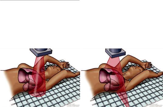
There are several differences between CBCT and conventional multislice, or multidetector CT (MDCT). The X-rays are produced by the source in CBCT in a cone-shaped distribution and collected by a high-resolution two-dimensional detector (Fig. 25.1). The C-arm does this in a single rotation as it moves around the patient who is immobile. As such, the Z-axis (craniocaudal dimension) of the acquisition is a function of the detector size. By comparison, MDCT is performed with X-rays being emitted in a thin, fan- shaped confguration. This output is then collected by a series of one-dimensional detector element rows (e.g., typical scanners are equipped with 64 though some with 256 and even 320 exist) as the patient table moves through the radiation feld [1]. The X-ray rotation combined with patient movement produces a helical, or “spiral,” pattern of radiation and leads to a Z-axis that is
Fig. 25.1 Schematic of X-ray emission by cone beam computed tomography in a cone-shape distribution (left) compared to multislice detector computed tomography in
a fan-beam shape distribution (right). (Image courtesy of the University of Texas MD Anderson Cancer Center)
Данная книга находится в списке для перевода на русский язык сайта https://meduniver.com/
436 |
B. F. Sabath and R. F. Casal |
|
|
dependent on the degree of table movement. The MDCT gantry takes approximately 0.4 s for a full rotation so even a fairly large section of a patient’s anatomy can be scanned in several seconds. CBCT takes upward of 20 s or more to acquire an image even though images are captured using a single rotation of the C-arm. Thus, even though MDCT requires multiple gantry rotations for a given body region, it is in actuality faster than CBCT. Moreover, the reconstruction algorithm is mathematically more complex for CBCT, leading to nearly 1 min of reconstruction time compared to what is effectively real-time reconstruction offered by MDCT [1]. Nevertheless, from a practical perspective, CBCT has an advantage specifc to bronchoscopy in that the C-arm remains positioned over the chest and does not have the patient’s head within it as with MDCT. This avoids any potential physical obstructions or collisions between the scanner and bronchoscope
and any other tools inserted through the airway. Moreover, while the patient moves in MDCT, the C-arm of the CBCT rotates around the patient who remains immobile, preventing dislodgement of bronchoscopic equipment.
Image Acquisition
CBCT and MDCT have somewhat similar spatial resolution. However, CBCT has decreased contrast capability by comparison, making the distinction between soft tissue structures less clear (Fig. 25.2). In fact, the image intensity of CBCT is not with calibrated Hounsfeld units as in MDCT but, rather, non-calibrated gray-scale units [35]. As a result, typical lung or soft tissue windows that are customary with MDCT are not possible with CBCT. Yet, images can be improved by increasing both the number of acquired images
Fig. 25.2 Representative axial plane image of right lung with target nodule (blue arrow) as seen by cone beam CT reconstruction (left) versus multidetector CT reconstruction (right). Notice how the CBCT image is truncated, not
capturing the entire right lung due to smaller imaging feld. Nevertheless, the area of interest and surrounding structures are adequately apprehended
25 Cone Beam Computed Tomography-Guided Bronchoscopy |
437 |
|
|
and the dose per image. This provides more data that can be reconstructed while also decreasing “noise,” leading to a more detailed image.
CBCT is nevertheless susceptible to different artifacts that can negatively affect image quality. CBCT can particularly be affected by scattered radiation compared to MDCT. With regard to bronchoscopy, this can be caused by the presence of the bronchoscope or biopsy tools that cause streak artifact. MDCT scanners are equipped with anti-scatter septae between their detector channels but these cannot be used with the at panel detectors of CBCT [1]. The collimation that is meant to flter and focus X-rays is wider in CBCT and, thus, image quality is reduced. Multiple techniques can be employed to attempt to reduce scatter but most are beyond the scope of this chapter. More applicable to the bronchoscopist using CBCT, interventions such as increasing the number of images or the dose per image can be attempted. Additionally, viewing the reconstructed images as either a multi-planar reconstruction or thin maximum intensity projection may reduce noise [35]. Artifact distortion can also occur due to the presence of nearby metallic objects (e.g., electrocardiographic monitoring leads) and these should be moved out of the feld of view as much as possible, at least during image acquisition.
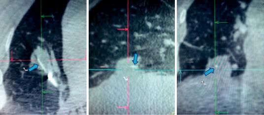
Motion artifact is another concern that can affect image quality. Lesions near the heart (or great vessels) and diaphragm are particularly susceptible to motion from the cardiac and respiratory cycles, respectively. Motion during the capture of the two-dimensional images will correspondingly lead to a blurred three-dimensional image. A breath-hold on the ventilator in a paralyzed patient can be performed to minimize or eliminate respiratory motion. There is no way to circumvent cardiac motion but software algorithms (currently in the research and development phase) may be able to make adjustments for this in the future [35]. A representative image of an intraoperative CT identifying the biopsy tool in the lesion is shown in Fig. 25.3.
There are also a few practical points to heed that can ensure optimal image acquisition and quality. First, the target lesion should be at the isocenter of the CBCT scanning feld. This is, essentially, the geometrical center point of the image feld. This will safeguard that not only the lesion but any other relevant anatomy (e.g., adjacent airways or nearby structures to avoid) is included within the captured image. CBCT systems each have a method of identifying the isocenter, such as light lasers in the anterior-posterior and medial-lateral planes that form a crosshair that are placed (from an external perspective) as near to the estimated location of the lesion as
a |
b |
c |
Fig. 25.3 Multiplanar reconstruction of intraoperative CT image demonstrating needle (blue arrow) within the lesion in axial (a), sagittal (b), and coronal (c) planes
Данная книга находится в списке для перевода на русский язык сайта https://meduniver.com/