- •Contents
- •What Is C#?
- •C# Versus Other Programming Languages
- •Preparing to Program
- •The Program Development Cycle
- •Your First C# Program
- •Types of C# Programs
- •Summary
- •Workshop
- •C# Applications
- •Basic Parts of a C# Application
- •Structure of a C# Application
- •Analysis of Listing 2.1
- •Object-Oriented Programming (OOP)
- •Displaying Basic Information
- •Summary
- •Workshop
- •Variables
- •Using Variables
- •Understanding Your Computer’s Memory
- •C# Data Types
- •Numeric Variable Types
- •Literals Versus Variables
- •Constants
- •Reference Types
- •Summary
- •Workshop
- •Types of Operators
- •Punctuators
- •The Basic Assignment Operator
- •Mathematical/Arithmetic Operators
- •Relational Operators
- •Logical Bitwise Operators
- •Type Operators
- •The sizeof Operator
- •The Conditional Operator
- •Understanding Operator Precedence
- •Converting Data Types
- •Understanding Operator Promotion
- •For Those Brave Enough
- •Summary
- •Workshop
- •Controlling Program Flow
- •Using Selection Statements
- •Using Iteration Statements
- •Using goto
- •Nesting Flow
- •Summary
- •Workshop
- •Introduction
- •Abstraction and Encapsulation
- •An Interactive Hello World! Program
- •Basic Elements of Hello.cs
- •A Few Fundamental Observations
- •Summary
- •Review Questions
- •Programming Exercises
- •Introduction
- •Essential Elements of SimpleCalculator.cs
- •A Closer Look at SimpleCalculator.cs
- •Simplifying Your Code with Methods
- •Summary
- •Review Questions
- •Programming Exercises
- •Introduction
- •Lexical Structure
- •Some Thoughts on Elevator Simulations
- •Concepts, Goals and Solutions in an Elevator Simulation Program: Collecting Valuable Statistics for Evaluating an Elevator System
- •A Deeper Analysis of SimpleElevatorSimulation.cs
- •Class Relationships and UML
- •Summary
- •Review Questions
- •Programming Exercises
- •The Hello Windows Forms Application
- •Creating and Using an Event Handler
- •Defining the Border Style of the Form
- •Adding a Menu
- •Adding a Menu Shortcut
- •Handling Events from Menus
- •Dialogs
- •Creating Dialogs
- •Using Controls
- •Data Binding Strategies
- •Data Binding Sources
- •Simple Binding
- •Simple Binding to a DataSet
- •Complex Binding of Controls to Data
- •Binding Controls to Databases Using ADO.NET
- •Creating a Database Viewer with Visual Studio and ADO.NET
- •Resources in .NET
- •Localization Nuts and Bolts
- •.NET Resource Management Classes
- •Creating Text Resources
- •Using Visual Studio.NET for Internationalization
- •Image Resources
- •Using Image Lists
- •Programmatic Access to Resources
- •Reading and Writing RESX XML Files
- •The Basic Principles of GDI+
- •The Graphics Object
- •Graphics Coordinates
- •Drawing Lines and Simple Shapes
- •Using Gradient Pens and Brushes
- •Textured Pens and Brushes
- •Tidying up Your Lines with Endcaps
- •Curves and Paths
- •The GraphicsPath Object
- •Clipping with Paths and Regions
- •Transformations
- •Alpha Blending
- •Alpha Blending of Images
- •Other Color Space Manipulations
- •Using the Properties and Property Attributes
- •Demonstration Application: FormPaint.exe
- •Why Use Web Services?
- •Implementing Your First Web Service
- •Testing the Web Service
- •Implementing the Web Service Client
- •Understanding How Web Services Work
- •Summary
- •Workshop
- •How Do Web References Work?
- •What Is UDDI?
- •Summary
- •Workshop
- •Passing Parameters and Web Services
- •Accessing Data with Web Services
- •Summary
- •Workshop
- •Managing State in Web Services
- •Dealing with Slow Services
- •Workshop
- •Creating New Threads
- •Synchronization
- •Summary
- •The String Class
- •The StringBuilder Class
- •String Formatting
- •Regular Expressions
- •Summary
- •Discovering Program Information
- •Dynamically Activating Code
- •Reflection.Emit
- •Summary
- •Simple Debugging
- •Conditional Debugging
- •Runtime Tracing
- •Making Assertions
- •Summary
GDI+: The .NET Graphics Interface
CHAPTER 3.5
FIGURE 3.5.9
Exploring region combination modes.
Transformations
You might have noticed a couple of commands in the previous example that moved the regions into position by applying a translation to them. There are two basic ways of applying transforms to graphical objects in the Framework. You can use the methods provided, such as Translate or Rotate, or you can specify an explicit transformation matrix to be used.
By far, the easiest way for dealing with these kinds of operations is to use the methods that wrap the underlying matrix manipulations for you.
These operations allow you to do the following:
•Translate—Move an object in the x or y plane by an offset.
•Rotate—Spin an object about the origin.
•RotateAt—Spin an object about a point other than the origin.
•Scale—Magnify or reduce an object in the x and y planes.
•Shear—Distort an object by changing its bounding rectangle into a bounding parallelogram.
357
3.5
T GDI+:RAPHICSGNTERFACEI . HE NET
A matrix performs these operations by performing a matrix operation, such as addition, subtraction, or multiplication to the current graphics transform. We mentioned right at the beginning of this chapter that graphical commands need to go through several translations
Windows Forms
358
PART III
between being drawn into the graphics system and finally being seen onscreen. This is referred to as the graphics pipeline. Think of commands going in one end, being changed according to the plumbing of the pipes, and emerging at the other end in a somewhat different state.
The things a matrix transforms are the individual positional coordinates of a graphical object. Every pixel drawn onscreen will have been transformed in the pipeline several times before it finally appears on the screen or printer.
The matrices used in the framework are a two dimensional 3×3 matrix. The matrix is constructed as shown in Figure 3.5.10.
The 3*3 matrix used by the >NET Matrix class
1 0 0
|
|
0 |
0 |
1 |
|
0 |
0 |
1 |
Linear part
Translation part
Always 0,0,1
FIGURE 3.5.10
The 3×3 Identity Matrix.
The matrix shown in Figure 3.5.10 is called the Identity Matrix. An identity matrix can be applied as a transformation to an object and have no effect on it. The Identity Matrix is normally the starting point for all transformations. The matrix used by GDI+ has some fixed values in the rightmost column. The part that is always 0,0,1 in the 3×3 matrix is used to allow a compound operation (for example, a linear calculation, such as rotation or scaling) to be followed by a translation in the same multiplication. This is known as an affined matrix calculation. To do an affined calculation on a matrix of n dimensions, the multiplication matrix used must be n+1 by n+1. Therefore, a 2D calculation requires a 3×3 matrix. For this reason, the third column of the matrix is always set to 0,0,1, and you cannot change it.
There are lots of books on graphics but, for the sake of completeness, the operations performed by the matrix on coordinates go as follows. The following example does a simple translation by an X and Y amount.
A coordinate is turned into a vector by adding a third, z column, to it. For example,
[10,5] becomes [10,5,1]
The dX and dY, or the translation part, of the matrix shown is 10,30.
GDI+: The .NET Graphics Interface
CHAPTER 3.5
This vector is multiplied by the matrix by working down each column in the following manner.
[10 , 5 , 1 ]
multiply…
1 0 0
0 1 0
dX dY 1
equals…
1*x 0*x 0*x
+ + +
0*y 1*y 0*y
+ + +
1*dX 1*dY 1*1
equals…
dx+x dy+y 1
equals…
20 35 1
Take the dummy component out, and you’re left with [20,35], which is [10,5] translated by [10,30].
A rotation about the origin is also performed in a similar manner. We’ll use 90 degrees, because the sine and cosine of 90 are easy to compute. The matrix for rotation is initialized as follows:
cosΘ sinΘ 0
-sinΘ cosΘ 0
0 0 1
So, cos(90)=0 and sin(90)=1 so, remembering to work down the columns, the matrix calculation looks like the following:
[ 10 , 5 , 1 ]
multiply…
359
3.5
T GDI+:RAPHICSGNTERFACEI . HE NET
Windows Forms
360
PART III
0 1 0
-1 0 0
0 0 1
equals…
0*x 1*x 0*x
+ + +
-1*y 0*y 0*y
+ + +
1*0 1*0 1*1
equals…
[ -5 , 10 , 1 ]
Chop off the extraneous 1, and you get [–5,10]
Taking two matrices and adding them or multiplying them together produces a resultant matrix. Successive additions or multiplications create a matrix that is the sum of all the operations performed so far. This means that you can do several operations on a matrix and they all accumulate, and then the transform in the matrix is applied to each and every pixel that the drawing command produces to obtain their resulting positions in the final output.
The order in which operations take place is very important too. For example, Rotate— Scale—Translate does not mean the same thing as Scale—Translate—Rotate. This implies that you also need to think about how the API commands apply the matrices you hand them. Do you multiply the current matrix by the one you just supplied or the one you have by the current matrix? Luckily, the calls to Rotate, Scale, and so on, have a flag that you can use to control the way matrices are worked on. MatrixOrder.Prepend, the default, applies the matrix you pass first, and then the current matrix. MatrixOrder.Append applies the requested operation after the current matrix is applied.
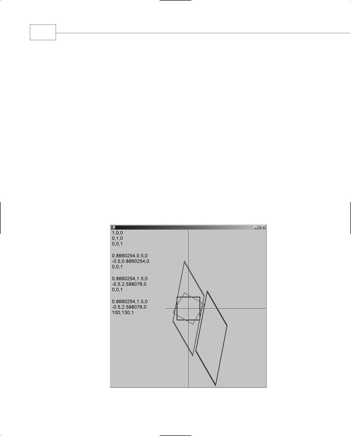
The following sequence illustrates the contents of a matrix as it evolves through many operations.
Matrix m=new Matrix() // Create an identity matrix
1 0 0
0 1 0
0 0 1
GDI+: The .NET Graphics Interface
CHAPTER 3.5
m.Rotate(30,MatrixOrder.Append); //rotate 30 degrees 0.8660254 0.5 0
-0.5 0.8660254 0 0 0 1
m.Scale((float)1,(float)3,MatrixOrder.Append); //magnify by 3 in the Y plane 0.8660254 1.5 0
-0.5 2.598076 0 0 0 1
m.Translate((float)100,(float)130,MatrixOrder.Append); //move by 100 X and 130 Y
0.8660254 1.5 0 -0.5 2.598076 0
100 130 1
As this sequence progresses, you can see how the matrix accumulates the operations with each successive call.
It is important to note that keeping track of the graphics matrix is very important, especially if you want to place many different objects onscreen, each with its own transformation. It is sometimes useful to put the current matrix into a known state, perhaps with the origin in a different place or zoomed in or out by scaling, and then perform other operations. Each operation should behave itself and leave the current matrix as it was found. Saving the state of the Graphics object in a GraphicsState can do this. A GraphicsState is filled with information by the Graphics.Save() method and restored with the Graphics.Restore(state) method. For example,
GraphicsState gs=theGraphics.Save(); // perform operations here...
theGraphics.Restore(gs);
//Graphics are back to their original state.
Listing 3.5.8 demonstrates the simple transformation sequence discussed previously, as well as the use of GraphicsState and other matrix manipulations in the context of some simple graphic shapes.
361
3.5
T GDI+:RAPHICSGNTERFACEI . HE NET
Windows Forms
362
PART III
LISTING 3.5.8 MatrixElements.cs: A Scene from the Matrix
1:using System;
2:using System.Drawing;
3:using System.Drawing.Drawing2D;
4:using System.Drawing.Text;
5:using System.Collections;
6:using System.ComponentModel;
7:using System.Windows.Forms;
8:using System.Data;
9:using System.Text;
10:
11:namespace matrixelements
12:{
13:public class MatrixElements : System.Windows.Forms.Form
14:{
15:void DumpMatrix(Graphics g, Matrix m, Point p)
16:{
17:StringBuilder sb=new StringBuilder();
18:sb.AppendFormat(“{0},\t{1},\t0\n{2},\t{3},\t0\n{4},\t{5},\t1”,
19:m.Elements[0],m.Elements[1],m.Elements[2],
20:m.Elements[3],m.Elements[4],m.Elements[5]);
21:GraphicsState s=g.Save();
22:g.ResetTransform();
23:g.DrawString(sb.ToString(),new Font(“Courier New”,(float)16),
24:new SolidBrush(Color.Black),p,StringFormat.GenericDefault);
25:g.Restore(s);
26:}
27:
28:void OnSize(object sender,EventArgs e)
29:{
30:Invalidate();
31:}
32:
33:void OnPaint(object sender, PaintEventArgs e)
34:{
35:GraphicsState gs;
36:Matrix m=new Matrix();
37:
38://position and draw the axes by translating the whole window
39:// so that the origin is in the center of the screen
40:e.Graphics.TranslateTransform((float)this.ClientRectangle.Width/2,
41: |
(float)this.ClientRectangle.Height/2); |
42:e.Graphics.DrawLine(new Pen(Color.Black,(float)1),0,-1000,0,1000);
43:e.Graphics.DrawLine(new Pen(Color.Black,(float)1),-100,0,1000,0);
45://Draw an ordinary square about the origin.
46:e.Graphics.DrawRectangle(new Pen(Color.Black,(float)3),
47: |
-50,-50,100,100); |
GDI+: The .NET Graphics Interface
CHAPTER 3.5
LISTING 3.5.8 Continued
48: DumpMatrix(e.Graphics,m,new Point(0,0)); 49:
50:m.Rotate(30,MatrixOrder.Append);
51:DumpMatrix(e.Graphics,m,new Point(0,100));
53:gs=e.Graphics.Save();
54:e.Graphics.MultiplyTransform(m);
55:e.Graphics.DrawRectangle(new Pen(Color.Red,3),
56: |
-50,-50,100,100); |
57: |
e.Graphics.Restore(gs); |
58: |
|
59:m.Scale(1,3,MatrixOrder.Append);
60:DumpMatrix(e.Graphics,m,new Point(0,200));
62:gs=e.Graphics.Save();
63:e.Graphics.MultiplyTransform(m);
64:e.Graphics.DrawRectangle(new Pen(Color.Green,3),
65: |
-50,-50,100,100); |
66: |
e.Graphics.Restore(gs); |
67: |
|
68:m.Translate(100,130,MatrixOrder.Append);
69:DumpMatrix(e.Graphics,m,new Point(0,300));
71:gs=e.Graphics.Save();
72:e.Graphics.MultiplyTransform(m);
73:e.Graphics.DrawRectangle(new Pen(Color.Blue,3),
74: |
-50,-50,100,100); |
75:e.Graphics.Restore(gs);
76:}
77:
78:public MatrixElements()
79:{
80:this.Paint+=new PaintEventHandler(OnPaint);
81:this.SizeChanged+=new EventHandler(OnSize);
82:}
83:
84:static void Main()
85:{
86:Application.Run(new MatrixElements());
87:}
88:}
89:}
Compile the code using the following command line:
363
3.5
T GDI+:RAPHICSGNTERFACEI . HE NET
csc /t:winexe matrixelements.cs
Windows Forms
364
PART III
Cutting to the chase, lines 40 and 41 create a matrix that shifts the origin to the center of the window. Lines 42 and 43 draw axis lines just to look nice and give a point of reference.
Lines 46 and 47 draw our reference square. This is the same drawing command used for all the other objects onscreen, and then line 48 dumps our identity matrix.
Line 50 rotates the matrix, which is again dumped to text, and then line 53 saves the graphics state so as not to mess up the origin. Line 54 uses the matrix, lines 55 and 56 draw our newly rotated square, and line 57 restores the world transform back to its origin-in-the-middle state.
Line 59 scales the matrix, making it 3 times taller than it is wide and stretching the output in the Y direction. Lines 62–66 use the transformation, draw the square, and return the world transform to our chosen default.
Line 68 then translates the matrix moving to the right and down. Line 69 shows the matrix settings and we round-off on lines 71–75 drawing the last, rotated, scaled, and translated square.
To draw the matrix data itself, lines 15–26 save the graphics state and reset the transform, place the text onscreen, and then returns the transform back to its original state before returning.
The final output from this program is shown in Figure 3.5.11.
FIGURE 3.5.11
Matrix transformations of a simple square.