
- •Contents
- •What Is C#?
- •C# Versus Other Programming Languages
- •Preparing to Program
- •The Program Development Cycle
- •Your First C# Program
- •Types of C# Programs
- •Summary
- •Workshop
- •C# Applications
- •Basic Parts of a C# Application
- •Structure of a C# Application
- •Analysis of Listing 2.1
- •Object-Oriented Programming (OOP)
- •Displaying Basic Information
- •Summary
- •Workshop
- •Variables
- •Using Variables
- •Understanding Your Computer’s Memory
- •C# Data Types
- •Numeric Variable Types
- •Literals Versus Variables
- •Constants
- •Reference Types
- •Summary
- •Workshop
- •Types of Operators
- •Punctuators
- •The Basic Assignment Operator
- •Mathematical/Arithmetic Operators
- •Relational Operators
- •Logical Bitwise Operators
- •Type Operators
- •The sizeof Operator
- •The Conditional Operator
- •Understanding Operator Precedence
- •Converting Data Types
- •Understanding Operator Promotion
- •For Those Brave Enough
- •Summary
- •Workshop
- •Controlling Program Flow
- •Using Selection Statements
- •Using Iteration Statements
- •Using goto
- •Nesting Flow
- •Summary
- •Workshop
- •Introduction
- •Abstraction and Encapsulation
- •An Interactive Hello World! Program
- •Basic Elements of Hello.cs
- •A Few Fundamental Observations
- •Summary
- •Review Questions
- •Programming Exercises
- •Introduction
- •Essential Elements of SimpleCalculator.cs
- •A Closer Look at SimpleCalculator.cs
- •Simplifying Your Code with Methods
- •Summary
- •Review Questions
- •Programming Exercises
- •Introduction
- •Lexical Structure
- •Some Thoughts on Elevator Simulations
- •Concepts, Goals and Solutions in an Elevator Simulation Program: Collecting Valuable Statistics for Evaluating an Elevator System
- •A Deeper Analysis of SimpleElevatorSimulation.cs
- •Class Relationships and UML
- •Summary
- •Review Questions
- •Programming Exercises
- •The Hello Windows Forms Application
- •Creating and Using an Event Handler
- •Defining the Border Style of the Form
- •Adding a Menu
- •Adding a Menu Shortcut
- •Handling Events from Menus
- •Dialogs
- •Creating Dialogs
- •Using Controls
- •Data Binding Strategies
- •Data Binding Sources
- •Simple Binding
- •Simple Binding to a DataSet
- •Complex Binding of Controls to Data
- •Binding Controls to Databases Using ADO.NET
- •Creating a Database Viewer with Visual Studio and ADO.NET
- •Resources in .NET
- •Localization Nuts and Bolts
- •.NET Resource Management Classes
- •Creating Text Resources
- •Using Visual Studio.NET for Internationalization
- •Image Resources
- •Using Image Lists
- •Programmatic Access to Resources
- •Reading and Writing RESX XML Files
- •The Basic Principles of GDI+
- •The Graphics Object
- •Graphics Coordinates
- •Drawing Lines and Simple Shapes
- •Using Gradient Pens and Brushes
- •Textured Pens and Brushes
- •Tidying up Your Lines with Endcaps
- •Curves and Paths
- •The GraphicsPath Object
- •Clipping with Paths and Regions
- •Transformations
- •Alpha Blending
- •Alpha Blending of Images
- •Other Color Space Manipulations
- •Using the Properties and Property Attributes
- •Demonstration Application: FormPaint.exe
- •Why Use Web Services?
- •Implementing Your First Web Service
- •Testing the Web Service
- •Implementing the Web Service Client
- •Understanding How Web Services Work
- •Summary
- •Workshop
- •How Do Web References Work?
- •What Is UDDI?
- •Summary
- •Workshop
- •Passing Parameters and Web Services
- •Accessing Data with Web Services
- •Summary
- •Workshop
- •Managing State in Web Services
- •Dealing with Slow Services
- •Workshop
- •Creating New Threads
- •Synchronization
- •Summary
- •The String Class
- •The StringBuilder Class
- •String Formatting
- •Regular Expressions
- •Summary
- •Discovering Program Information
- •Dynamically Activating Code
- •Reflection.Emit
- •Summary
- •Simple Debugging
- •Conditional Debugging
- •Runtime Tracing
- •Making Assertions
- •Summary

GDI+: The .NET Graphics Interface
349
CHAPTER 3.5
The meat of this application is substantially similar to that shown in Listing 3.5.4. The points of interest are lines 83–86, where the Bezier is drawn, and lines 92–96, which show you how to draw dashed lines. The image shown in Figure 3.5.4 is a screenshot of the application and shows how the Bezier control points are used to add direction and tension to a particular node.
FIGURE 3.5.4
The Bezier curve in action.
An array of points can also be used to create a multi-segmented Bezier Spline. The array must have a multiple of four points and is arranged as follows:
Point[0] = Start point of line segment 1
Point[1] = Control point for the start point
Point[2] = Control point for the end point
Point[3] = End point for line segment and start point of line segment 2
Point[4] = Control point for the start point of line segment 2
And so on, giving 4 initial points plus three for each subsequent line segment.
The GraphicsPath Object
GDI+ Graphics Paths are a convenient way of collecting together a number of graphical shapes, or their boundaries at least, into a single unit. A path, once created, can be manipulated in its entirety, filled, stroked, or used to perform other graphical operations, such as being used to create a clipping region.
Any combination of the following graphical primitives can be placed in a Path object:
•Arcs
•Bezier Splines
•Cardinal splines
3.5
T GDI+:RAPHICSGNTERFACEI . HE NET

Windows Forms
350
PART III
•Ellipses
•Lines
•Paths
•Pie segments
•Polygons
•Rectangles
•Character Glyphs from Strings
The following code snippet produces the result seen in Figure 3.5.5.
void OnPaint(object sender, PaintEventArgs e)
{
GraphicsPath p=new GraphicsPath(); p.AddEllipse(10,10,100,100); p.AddRectangle(new Rectangle(0,0,120,120)); Pen pen=new Pen(Color.Black,1); e.Graphics.DrawPath(pen,p);
pen.Dispose();
}
FIGURE 3.5.5
Two figures in a GraphicsPath.
Filling the path by substituting a suitable brush and fill command produces the following effect (see Figure 3.5.6):
SolidBrush brush = new SolidBrush(Color.Blue); e.Graphics.FillPath(brush,p);
FIGURE 3.5.6
A filled path.

GDI+: The .NET Graphics Interface
351
CHAPTER 3.5
The square part of the path has been filled and the circle has not. This is because the graphics FillMode for the path is set to the default setting, Alternate.
To fill everything inside the outermost boundary of the shape, set the FillMode to Winding.
Adding Text and Other Paths
One path can be added to another quite simply by calling the AddPath method. The following code snippet creates a second path and adds it to the one shown in Figure 3.5.5.
void OnPaint(object sender, PaintEventArgs e)
{
GraphicsPath p=new GraphicsPath(); p.AddEllipse(10,10,100,100); p.AddRectangle(new Rectangle(0,0,120,120)); Pen pen=new Pen(Color.Black,1); GraphicsPath p2=new GraphicsPath();
Point[] tripoint=new Point[3]; tripoint[0]=new Point(80,10); tripoint[1]=new Point(80,110); tripoint[2]=new Point(150,60); p2.AddClosedCurve(tripoint,(float)0); p2.AddPath(p,true);
SolidBrush brush = new SolidBrush(Color.Blue); e.Graphics.FillPath(brush,p2); e.Graphics.DrawPath(pen,p2);
}
Now the image displayed is the sum of the two paths. Figure 3.5.7 shows the output from the modified OnPaint handler.
FIGURE 3.5.7
The combination of two paths
3.5
T GDI+:RAPHICSGNTERFACEI . HE NET
Placing text in a path is a great way of creating text effects. A text path only contains the glyph outlines of the letters used. These outlines can be used to create clip paths, filled with patterns or colors, scaled, rotated, or otherwise transformed to make some pretty impressive effects.

Windows Forms
352
PART III
Modifying the code in our phantom OnPaint will illustrate again how this is accomplished.
void OnPaint(object sender, PaintEventArgs e)
{
GraphicsPath p=new GraphicsPath(); p.AddString(“AYBABTU”,FontFamily.GenericSansSerif,
0,(float)72,new Point(0,0), StringFormat.GenericDefault);
SolidBrush brush = new SolidBrush(Color.Blue); e.Graphics.FillPath(brush,p); brush.Dispose();
}
We’ll continue this discussion in the next section because it leads nicely into that topic.
Clipping with Paths and Regions
A region is a description of some enclosed shape that can be used as a mask in which to perform graphical operations. Regions can be regular shapes, like rectangles or ellipses; they can also be irregular, perhaps created from curves or text glyphs. Because regions can be created from paths, it is possible to have very complex, clipped shapes. Going back again to our previous text path example, we can create a clipping region from it and use it for other interesting things.
In the example shown in Listing 3.5.6, we use a path, filled with a text string, as a mask for randomly positioned ellipses of color that splatter the window but are clipped by the glyph outlines of the text.
LISTING 3.5.6 ClipToPath.cs: Using a Path to Clip the Drawing Area
1:using System;
2:using System.Drawing;
3:using System.Drawing.Drawing2D;
4:using System.Collections;
5:using System.ComponentModel;
6:using System.Windows.Forms;
7:using System.Data;
8:
9:namespace Clipping
10:{
11:public class ClipToPath : System.Windows.Forms.Form
12:{
13:
14:Timer timer;
15:GraphicsPath p;
16:bool dirty;

GDI+: The .NET Graphics Interface
CHAPTER 3.5
LISTING 3.5.6 Continued
17:
18:void OnPaint(object sender, PaintEventArgs e)
19:{
20:Random r=new Random();
21:SolidBrush brush = new SolidBrush(
22: |
Color.FromArgb(r.Next(255), |
23: |
r.Next(255), |
24: |
r.Next(255))); |
25:e.Graphics.SetClip(p);
26:e.Graphics.FillEllipse(brush,
27: |
r.Next(500), |
28: |
r.Next(200), |
29: |
r.Next(20), |
30: |
r.Next(20)); |
31:brush.Dispose();
32:}
33:
34:void OnTick(object sender, EventArgs e)
35:{
36:Invalidate();
37:}
38:
39:protected override void OnPaintBackground(PaintEventArgs e)
40:{
41:if(dirty)
42:{
43: |
e.Graphics.ResetClip(); |
44: |
SolidBrush b=new SolidBrush(this.BackColor); |
45: |
e.Graphics.FillRectangle(b, this.ClientRectangle); |
46: |
dirty = false; |
47: |
b.Dispose(); |
48:}
49:}
51:void OnSized(object sender, EventArgs e)
52:{
53:dirty=true;
54:Invalidate();
55:}
56:
57:public ClipToPath()
58:{
59:
60:p=new GraphicsPath();
61:p.AddString(“AYBABTU”,FontFamily.GenericSansSerif,
353
3.5
T GDI+:RAPHICSGNTERFACEI . HE NET

354 |
Windows Forms |
|
PART III |
||
|
|
LISTING 3.5.6 |
Continued |
|
62: |
|
0,(float)72,new Point(0,0), |
|
63: |
|
StringFormat.GenericDefault); |
|
64: |
|
dirty=true; |
|
65: |
|
this.Paint+=new PaintEventHandler(OnPaint); |
|
66: |
|
this.SizeChanged+=new EventHandler(OnSized); |
|
67: |
|
timer = new Timer(); |
|
68: |
|
timer.Interval=10; |
|
69: |
|
timer.Tick+=new EventHandler(OnTick); |
|
70: |
|
timer.Enabled=true; |
|
71: |
} |
|
|
72: |
|
|
73:static void Main()
74:{
75:Application.Run(new ClipToPath());
76:}
77:}
78:}
The path is created once on lines 59–62 and stored for use later. Then a timer is initialized to enable the periodic refresh of the page.
Lines 39–48 handle the repaint of the background if the window is resized or on the first draw.
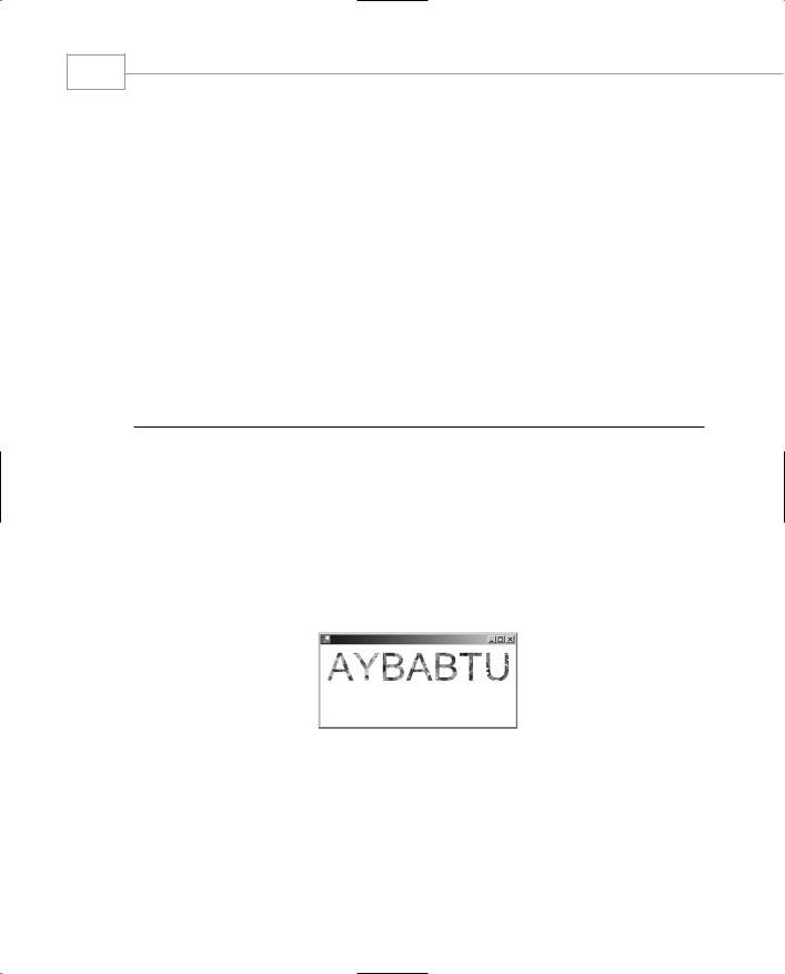
Finally, line 25 selects the clip-path into the Graphics object. The following lines place a random blob of color on the page; this might or might not be seen, depending on its coincidence with the clipping path.
After a while, the output from the application looks something like the image in Figure 3.5.8.
FIGURE 3.5.8
Painting clipped to a path.
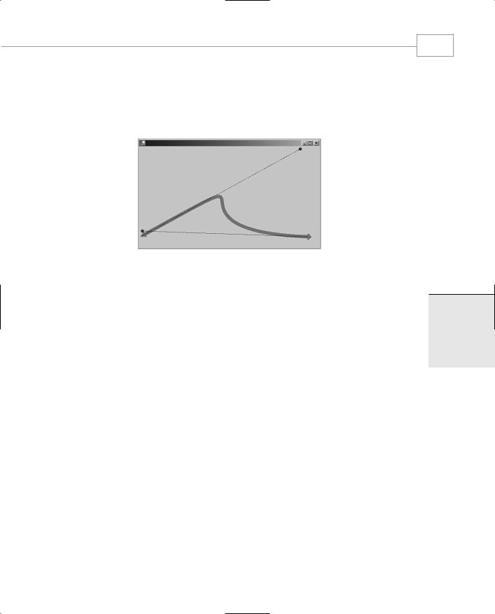
Operations on regions are different from those on paths. A path specifies a set of boundaries, a region specifies an area or group of areas to be used as a mask. Regions can be combined in several ways. The operation is controlled by the CombineMode enumeration. Listing 3.5.7 illustrates the use of regions in four different modes.

GDI+: The .NET Graphics Interface
CHAPTER 3.5
LISTING 3.5.7 Regions.cs: Combining Regions in Different Ways
1:using System;
2:using System.Drawing;
3:using System.Drawing.Drawing2D;
4:using System.Collections;
5:using System.ComponentModel;
6:using System.Windows.Forms;
7:using System.Data;
8:
9:namespace regions
10:{
11:/// <summary>
12:/// Summary description for Form1.
13:/// </summary>
14:public class RegionsTest : System.Windows.Forms.Form
15:{
16:void PaintRegions(Graphics g,CombineMode m,
Point offset,string text)
17: |
{ |
18: |
Region ra,rb; |
19: |
GraphicsPath p=new GraphicsPath(); |
20: |
p.AddRectangle(new Rectangle(60,60,120,120)); |
21: |
ra=new Region(p); |
22: |
p=new GraphicsPath(); |
23: |
p.AddEllipse(0,0,120,120); |
24: |
rb=new Region(p); |
25: |
ra.Translate(offset.X,offset.Y ); |
26: |
rb.Translate(offset.X,offset.Y); |
27: |
g.SetClip(ra,CombineMode.Replace); |
28: |
g.SetClip(rb,m); |
29: |
SolidBrush brush=new SolidBrush(Color.Black); |
30: |
g.FillRectangle(brush,this.ClientRectangle); |
31: |
g.ResetClip(); |
32: |
g.DrawString(text, |
33: |
new Font(“Ariel”,(float)16), |
34: |
brush,(float)offset.X+60,(float)offset.Y+220); |
35: |
} |
36: |
|
37: |
void OnPaint(object sender, PaintEventArgs e) |
38: |
{ |
39: |
// A union of two regions... |
40: |
PaintRegions(e.Graphics,CombineMode.Union, |
41: |
new Point(0,0),”Union”); |
42: |
// the intersection of two regions |
43: |
PaintRegions(e.Graphics,CombineMode.Intersect, |
44: |
new Point(250,0),”Intersect”); |
355
3.5
T GDI+:RAPHICSGNTERFACEI . HE NET

Windows Forms
356
PART III
LISTING 3.5.7 Continued
45:// Region exclusive or
46:PaintRegions(e.Graphics,CombineMode.Xor,
47: new Point(500,0),”Xor”);
48:// The complement of the two regions
49:PaintRegions(e.Graphics,CombineMode.Complement,
50: new Point(0,250),”Complement”);
51:// Exclusion.
52:PaintRegions(e.Graphics,CombineMode.Exclude,
53: |
new Point(250,250),”Exclude”); |
54: |
} |
55: |
|
56:public RegionsTest()
57:{
58:this.Paint+=new PaintEventHandler(OnPaint);
59:this.Size = new Size(800,800);
60:}
61:
62:static void Main()
63:{
64:Application.Run(new RegionsTest());
65:}
66:}
67:}
OnPaint (lines 37–54) repeatedly calls the PaintRegions method with a distinct CombineMode setting, some positional information, and an identifying string. The PaintRegions method (lines 16–35) begins by declaring two regions, ra and rb, and filling them with a circle and a rectangle. Lines 25 and 26 ensure that the regions are moved into position ready for display, and then line 27 selects the first clip region, replacing the one that already exists in the Graphics object. The second region is combined with the CombineMode, supplied on line 28, and the whole rectangle of the client area filled with black. Note that only the area inside the clipped region is filled. The program then removes the clipping region on line 31 to draw the information text on lines 32–34.
Output from this program is shown in Figure 3.5.9.