

HPR 260 Manual Instrution
.pdfINSTALLATION
Gas regulators
Low-quality gas regulators do not provide consistent supply pressures and can result in poor cut quality and system operation problems. Use a high-quality, 1-stage, gas regulator to maintain consistent gas supply pressure, if using liquid cryogenic or bulk storage. Use a high-quality, 2-stage, gas regulator to maintain consistent gas supply pressure from high pressure gas cylinders.
The high-quality gas regulators listed below are available from Hypertherm and meet U.S. Compressed Gas Association (CGA) specifications. In other countries, select gas regulators that conform to national or local codes.
2-stage regulator |
Single stage regulator |
Part |
|
|
Number |
Description |
Qty. |
128544 |
Kit: Oxygen, 2-stage * |
1 |
128545 |
Kit: Inert Gas, 2-stage |
1 |
128546 |
Kit: Hydrogen (H5, H35 and methane) 2-stage |
1 |
128547 |
Kit: Air, 2-stage |
1 |
128548 |
Kit: 1-stage (for use with cryogenic liquid nitrogen or oxygen) |
1 |
022037 |
Oxygen, 2-stage |
1 |
022038 |
Inert gas, 2-stage |
1 |
022039 |
Hydrogen/methane, 2-stage |
3 |
022040 |
Air, 2-stage |
1 |
022041 |
Line regulator, 1-stage |
1 |
* Kits include appropriate fittings
3-38 |
HPR260 Auto Gas Instruction Manual |
0
INSTALLATION
Supply gas plumbing
Rigid copper plumbing or suitable flexible hose may be used for all gas supplies. Do not use steel or aluminum pipe. After installation, pressurize the entire system and check for leaks.
Recommended hose diameters are 9.5 mm (3/8 in) for lengths < 23 m (75 ft) and 12.5 mm (1/2 in) for lengths > 23 m (75 ft).
For flexible-hose systems, use a hose designed for inert gas to carry air, nitrogen or argon-hydrogen.
Caution: When configuring the selection console to the supply gases, make sure that all hoses, hose connections and fittings are acceptable for use with oxygen, argon-hydrogen and methane. Installation must be made in accordance with local or national codes.
Note: When cutting with oxygen as the plasma gas, air must also be connected to the selection console to achieve the proper mixtures in the preflow and cutflow modes.
WARNING
CUTTING WITH OXYGEN CAN CAUSE FIRE OR EXPLOSION
Cutting with oxygen as the plasma gas can cause a potential fire hazard due to the oxygen-enriched atmosphere that it creates. As a precaution, Hypertherm recommends that an exhaust ventilation system be installed when cutting with oxygen.
Flashback arrestors are required (unless not available for specific gases or required pressures) to prevent fire from propagating back to supply gas.
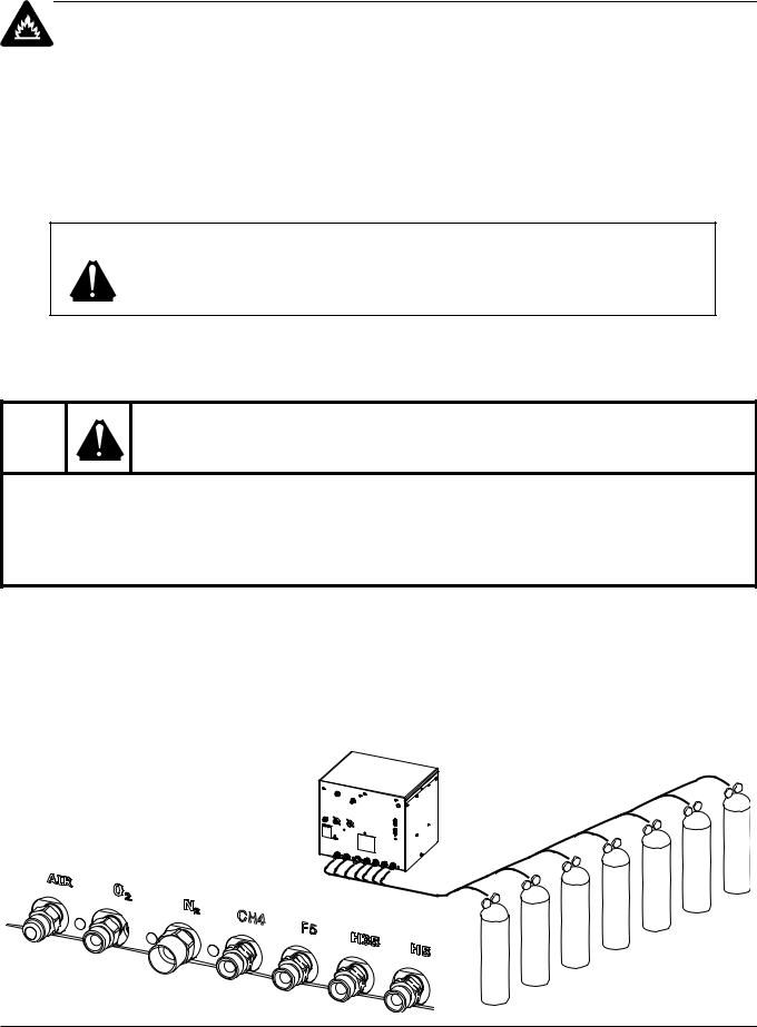
Connect the supply gases
Connect the supply gases to the selection console. Torch leads must be purged between gas changes.
Fitting |
Size |
|
|
Air |
9/16 – 18, JIC, #6 |
|
|
O2 |
9/16 – 18, RH |
|
(oxygen) “B” |
|
|
N2 |
5/8 – 18, RH, internal |
|
(Inert Gas) “B” |
|
|
CH4, F5, |
9/16 – 18 LH, |
H35 and H5 |
(Fuel Gas)”B” |
|
|
HPR260 Auto Gas Instruction Manual |
3-39 |
0
INSTALLATION
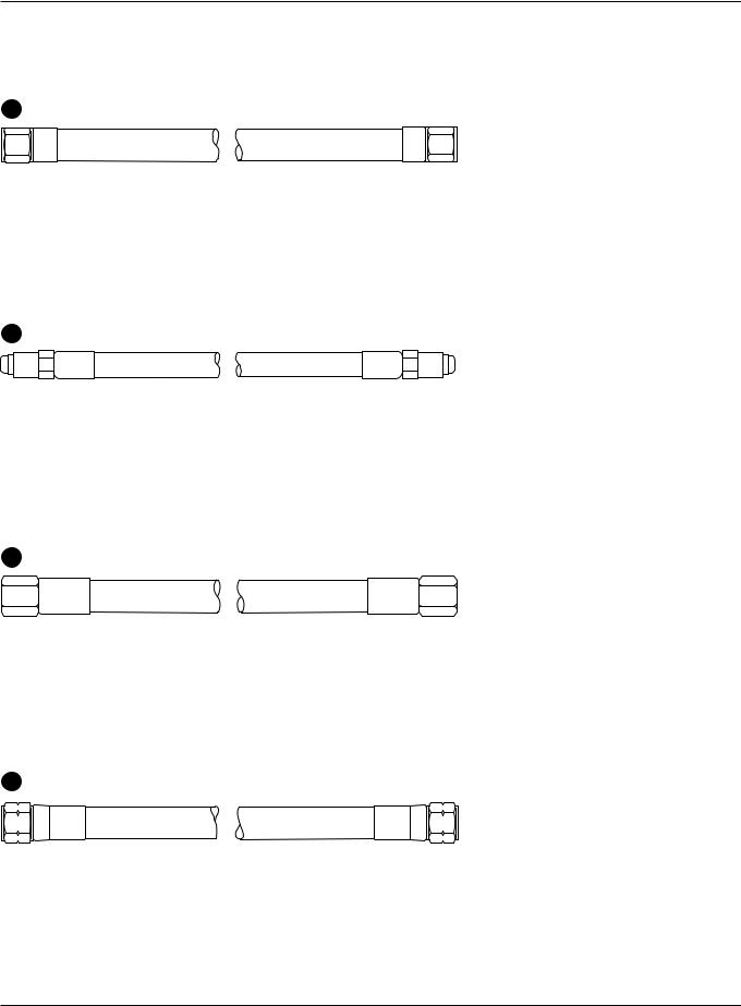
Supply gas hoses
12 Oxygen hose
Part no. |
Length |
Part no. |
Length |
|
|
|
|
024205 |
7.5 m (25 ft) |
024738 |
25 m (82 ft) |
024760 |
10 m (35 ft) |
024206 |
35 m (115 ft) |
024155 |
15 m (50 ft) |
024159 |
45 m (150 ft) |
024761 |
20 m (65 ft) |
024762 |
75 m (250 ft) |
|
|
|
|
13 Nitrogen hose
Part no. |
Length |
Part no. |
Length |
|
|
|
|
024134 |
7.5 m (25 ft) |
024116 |
35 m (115 ft) |
024112 |
15 m (50 ft) |
024120 |
45 m (150 ft) |
024763 |
20 m (65 ft) |
024764 |
75 m (250 ft) |
024739 |
25 m (82 ft) |
|
|
|
|
|
|
14 Air hose
Part no. |
Length |
Part no. |
Length |
|
|
|
|
024659 |
7.5 m (25 ft) |
024740 |
25 m (82 ft) |
024765 |
10 m (35 ft) |
024676 |
35 m (115 ft) |
024660 |
15 m (50 ft) |
024678 |
45 m (150 ft) |
024766 |
20 m (65 ft) |
024767 |
75 m (250 ft) |
|
|
|
|
15 H35, H5, CH4 or F5 hose
Part no. |
Length |
Part no. |
Length |
|
|
|
|
024768 |
3 m (10 ft) |
024741 |
25 m (82 ft) |
024384 |
7.5 m (25 ft) |
024742 |
35 m (115 ft) |
024769 |
10 m (35 ft) |
024743 |
45 m (150 ft) |
024656 |
15 m (50 ft) |
024771 |
60 m (200 ft) |
024770 |
20 m (65 ft) |
024772 |
75 m (250 ft) |
|
|
|
|
3-40 HPR260 Auto Gas Instruction Manual
0

Section 4
OPERATION
In this section:
Daily start-up............................................................................................................................................................. |
4-2 |
Check torch ...................................................................................................................................................... |
4-2 |
Power indicators ....................................................................................................................................................... |
4-3 |
General ............................................................................................................................................................ |
4-3 |
Power supply ................................................................................................................................................... |
4-3 |
Selection console ............................................................................................................................................ |
4-3 |
Metering console.............................................................................................................................................. |
4-3 |
CNC controller requirements .................................................................................................................................... |
4-4 |
CNC screen examples.............................................................................................................................................. |
4-5 |
Main (control) screen ....................................................................................................................................... |
4-5 |
Diagnostic screen............................................................................................................................................. |
4-6 |
Test screen....................................................................................................................................................... |
4-7 |
Cut chart screen............................................................................................................................................... |
4-8 |
Consumable selection .............................................................................................................................................. |
4-9 |
Mild steel .......................................................................................................................................................... |
4-9 |
Stainless steel .................................................................................................................................................. |
4-9 |
Aluminum ....................................................................................................................................................... |
4-10 |
Install consumables................................................................................................................................................. |
4-11 |
Cut charts ............................................................................................................................................................... |
4-12 |
Marking .......................................................................................................................................................... |
4-12 |
Consumables for mirror-image cutting ........................................................................................................... |
4-12 |
Estimated kerf width compensation ............................................................................................................... |
4-13 |
Changing consumable parts ................................................................................................................................... |
4-40 |
Remove consumables.................................................................................................................................... |
4-40 |
Inspect consumables ..................................................................................................................................... |
4-41 |
Inspect torch................................................................................................................................................... |
4-42 |
Inspect electrode pit depth ............................................................................................................................. |
4-43 |
Replace torch water tube........................................................................................................................................ |
4-44 |
Common cutting faults ............................................................................................................................................ |
4-45 |
How to optimize cut quality ..................................................................................................................................... |
4-46 |
Tips for table and torch................................................................................................................................... |
4-46 |
Plasma set-up tips.......................................................................................................................................... |
4-46 |
Maximize the life of consumable parts ........................................................................................................... |
4-46 |
Additional factors of cut quality ...................................................................................................................... |
4-47 |
Additional improvements................................................................................................................................ |
4-48 |
HPR260 Auto Gas Instruction Manual |
4-1 |
0

OPERATION
Daily start-up
Prior to start-up, ensure that your cutting environment and that your clothing meet the safety requirements outlined in the Safety section of this manual.
Check torch
WARNING
Before operating this system, you must read the Safety section thoroughly. Turn OFF the power supply's main disconnect switch before proceeding with the following steps.
1.Turn main disconnect switch to the power supply OFF.
2.Remove the consumables from the torch and check for worn or damaged parts. Always place the consumables on a clean, dry, oil-free surface after removing. Dirty consumables can cause the torch to malfunction.
•Refer to Changing consumable parts later in this section for details and for parts inspection tables.
•Refer to the Cut charts to choose the correct consumables for your cutting needs.
3.Replace consumable parts. Refer to Changing consumable parts later in this section for details.
4.Ensure that the torch is perpendicular to the workpiece.
Shield cap |
Shield |
Retaining cap |
Nozzle |
Swirl ring |
Electrode |
Current ring |
Torch |
4-2 |
HPR260 Auto Gas Instruction Manual |
0
OPERATION
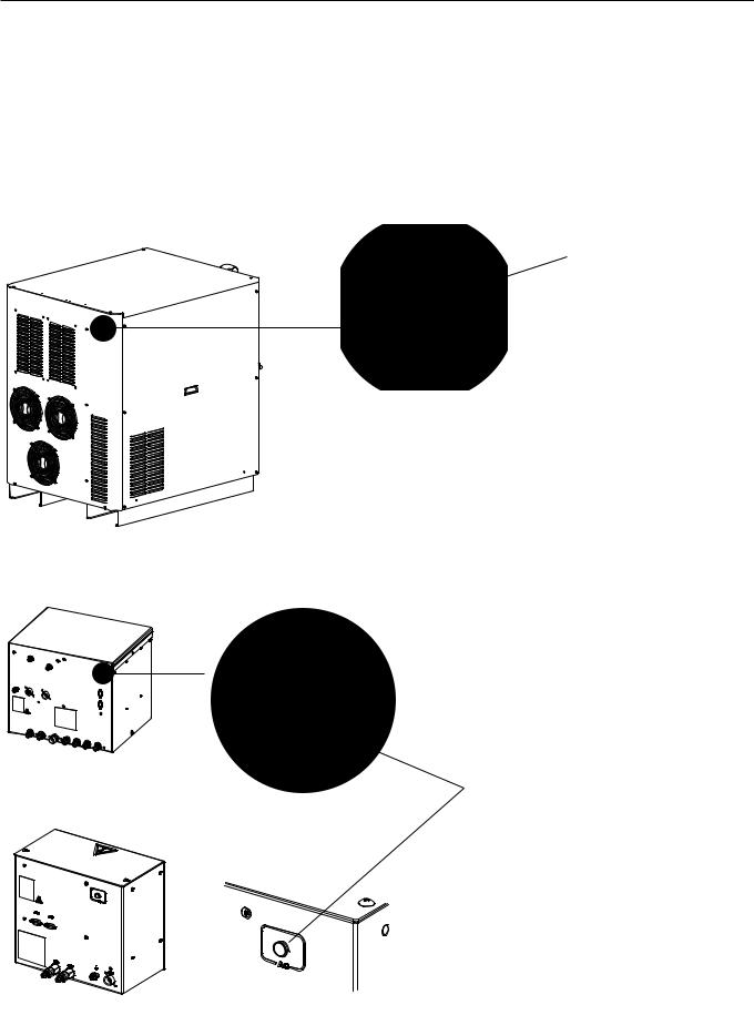
Power indicators
General
Power for the system is controlled by the CNC. The power supply, selection console and metering console each have an LED lamp that illuminates when power is supplied to the component.
Power supply
Green indicator
Selection console
Green indicator
Metering console
|
|
|
|
|
|
|
|
|
|
|
|
|
|
|
|
|
|
|
|
HPR260 Auto Gas Instruction Manual |
4-3 |
|||
0

OPERATION
CNC controller requirements
Base required elements
The following elements should be able to be displayed and adjusted on the CNC for setup and basic system information. The plasma system needs this group for basic setup and operation capability.
1.Remote On/Off
2.Ability to display and adjust the basic plasma process setpoints (command ID #95)
a.Current set-point
b.Plasma preflow
c.Plasma cutflow
d.Shield preflow
e.Shield cutflow
f.Plasma gas type
g.Shield gas type
h.Gas mixing setpoints
3.Display basic system information
a.System error code
b.Gas and PS firmware version
4.Manual pump control
Required real time elements
The following elements should be able to be displayed in real time while cutting. This is necessary for troubleshooting and diagnostic purposes.
5.Display line voltage
6.Display chopper current
7.Display work lead current
8.Display system status code
9.Display chopper temperature
10.Display transformer temperature
11.Display coolant temperature
12.Display coolant flow
13.Display pressure transducers
Required diagnostic elements
These elements provide additional diagnostic capability to the system for troubleshooting gas-delivery problems. The CNC should be capable of executing these commands and displaying the relevant information for the respective test according to the serial protocol guidelines.
14.Test preflow gases
15.Test cutflow gases
16.Inlet leak test
17.System leak test
18.System flow test
4-4 |
HPR260 Auto Gas Instruction Manual |
0
OPERATION
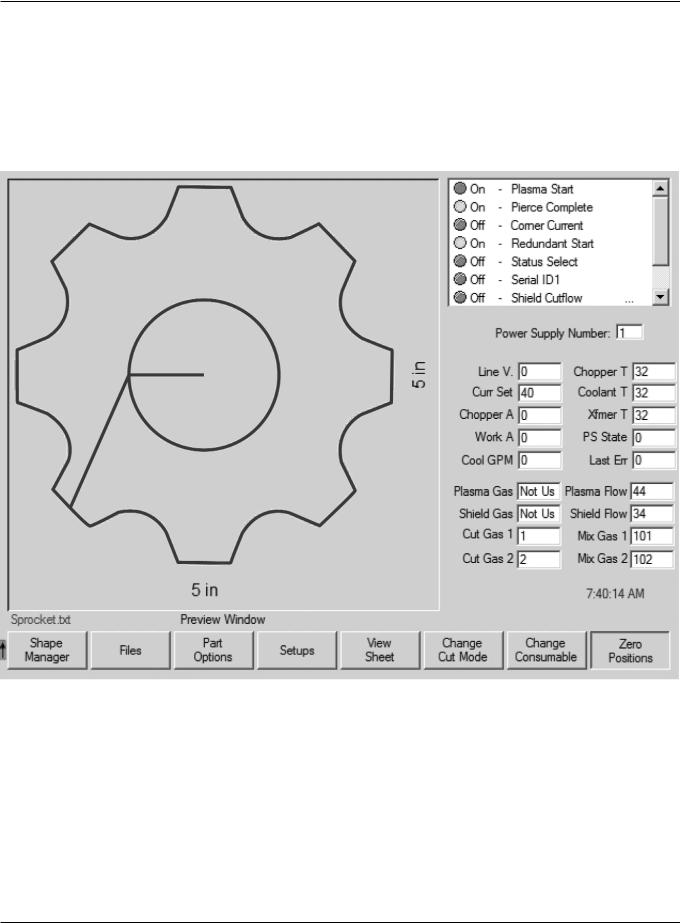
CNC screen examples
The screens shown are for reference. The screens you work with may be different, but should include the functions listed on the previous page.
Main (control) screen
HPR260 Auto Gas Instruction Manual |
4-5 |
0
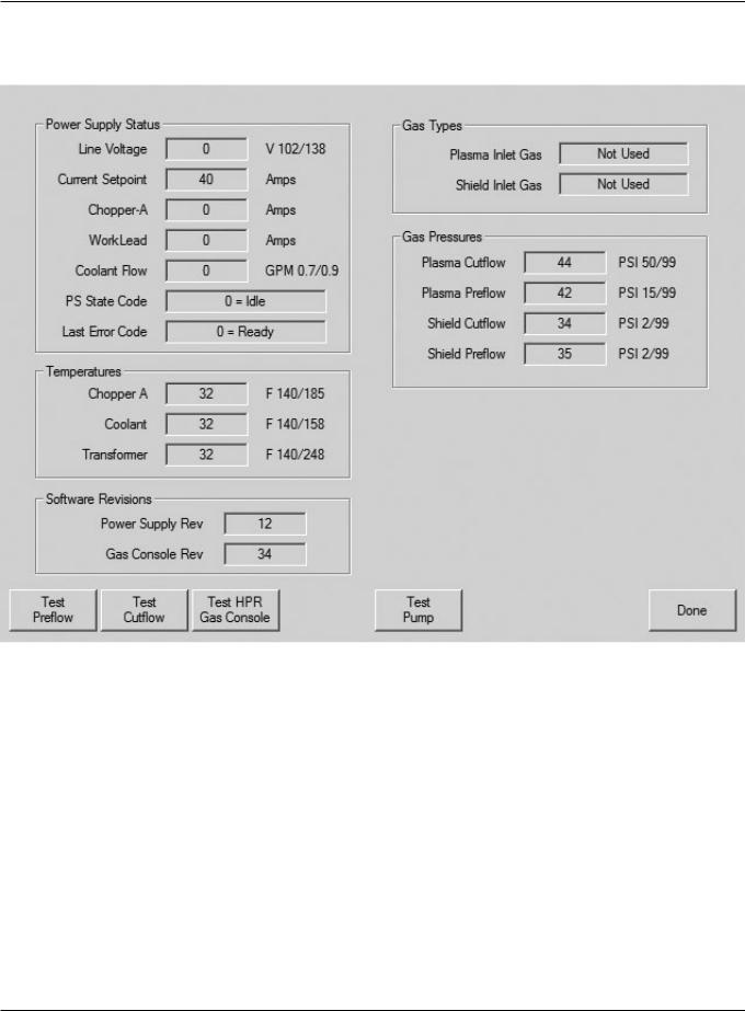
OPERATION
Diagnostics screen
4-6 |
HPR260 Auto Gas Instruction Manual |
0
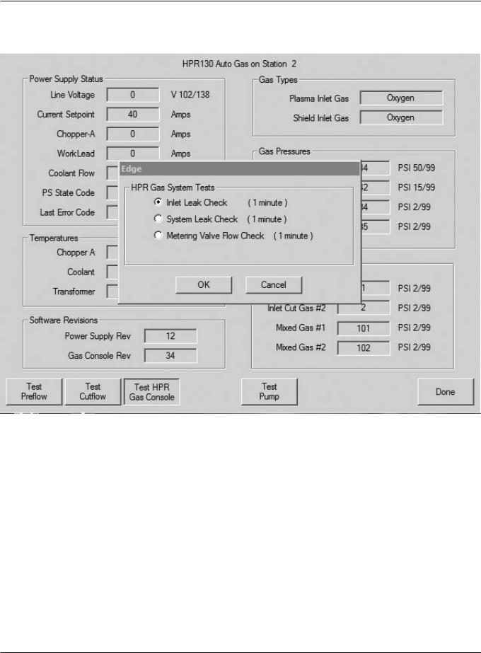
OPERATION
Test screen
HPR260 Auto Gas Instruction Manual |
4-7 |
0