

HPR 260 Manual Instrution
.pdfINSTALLATION
11 Work lead
|
Work table |
|
Power supply |
Part no. |
Length |
Part no. |
Length |
123829 |
1.5 m (5 ft) |
123819 |
20 m (65 ft) |
123816 |
3 m (10 ft) |
123775 |
25 m (82 ft) |
123817 |
4.5 m (15 ft) |
123776 |
35 m (115 ft) |
123773 |
7.5 m (25 ft) |
123777 |
45 m (150 ft) |
123818 |
10 m (35 ft) |
123771 |
60 m (200 ft) |
123774 |
15 m (50 ft) |
123772 |
75 m (250 ft) |
Work lead
Work lead
Lower frame of work table (typical).
3-28 |
HPR260 Auto Gas Instruction Manual |
0
INSTALLATION
Torch connections
Connect the torch to the torch lead assembly
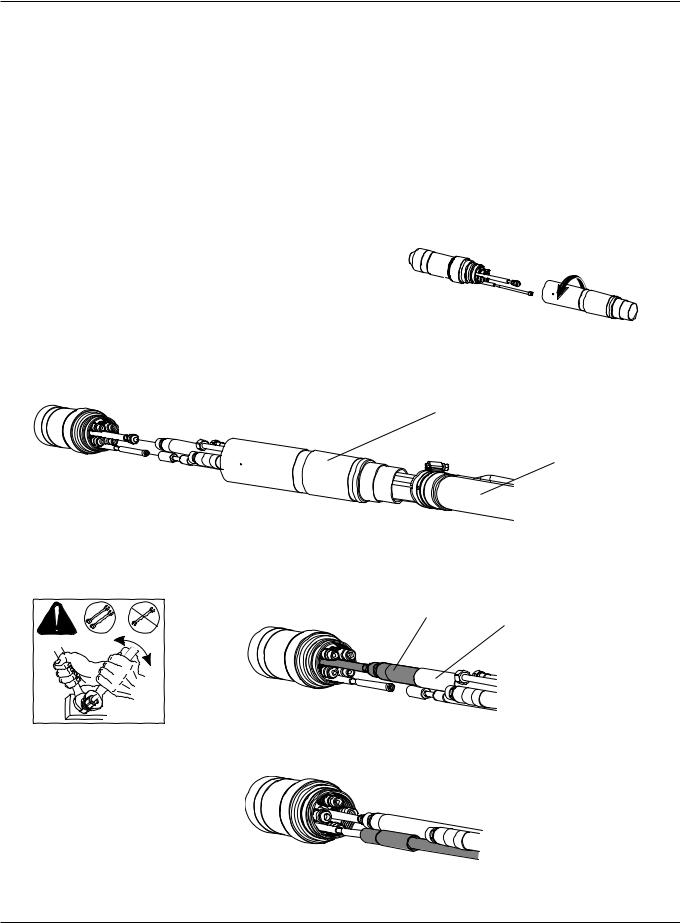
1. Uncoil the first 2 meters (6.5 feet) of the torch lead assembly on a flat surface.
2. Remove the mounting sleeve from the torch assembly.
3.Push back the braided cover and slide the sleeve over leads. Align the torch with the hoses in the lead assembly. The hoses must not be twisted. They are taped together to help prevent twisting.
Sleeve
Braided cover
4.Remove the plastic insulator from the torch and slide it onto the coolant IN hose (green) on the lead assembly. Connect the coolant IN hose to the torch.
Coolant IN hose
Plastic insulator
2WRENCHES
5. Connect the pilot arc lead. Tighten by hand only.
HPR260 Auto Gas Instruction Manual |
3-29 |
1
INSTALLATION
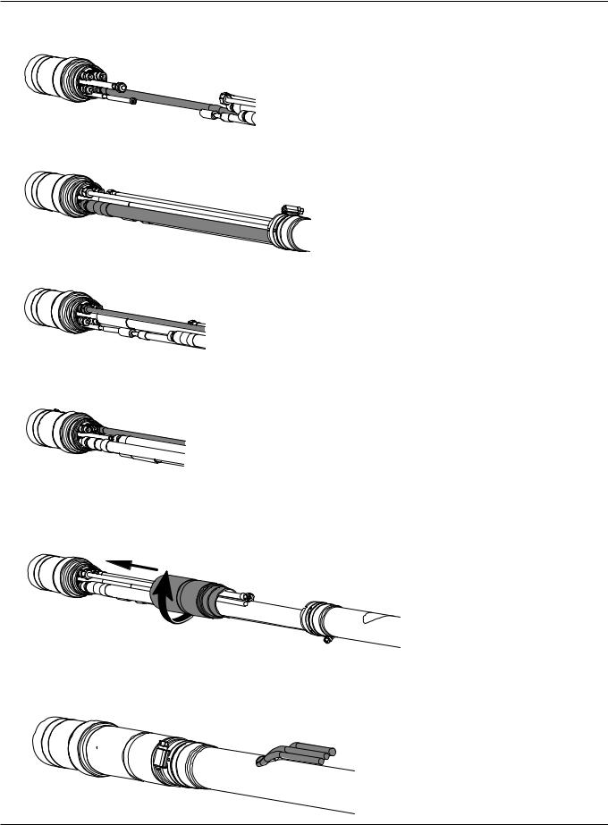
6. Connect the plasma vent hose.
7. Connect the coolant return hose (red).
8. Connect the plasma gas hose.
9. Connect the shield gas hose.
10.Position the plastic insulator so that it covers the coolant IN hose (green) connection. Wrap the bundle of hoses with electrical tape to prevent the insulator from moving. Slide the torch sleeve over connections and screw it onto the torch body.
11.Slide the braided cover up to the torch sleeve. Make sure that the plasma, shield and vent hoses are routed through the hole in the braided cover. Loosen the hose clamp on the braided cover, slide the braided cover and clamp over the sleeve and tighten the clamp.
3-30 |
HPR260 Auto Gas Instruction Manual |
0
INSTALLATION
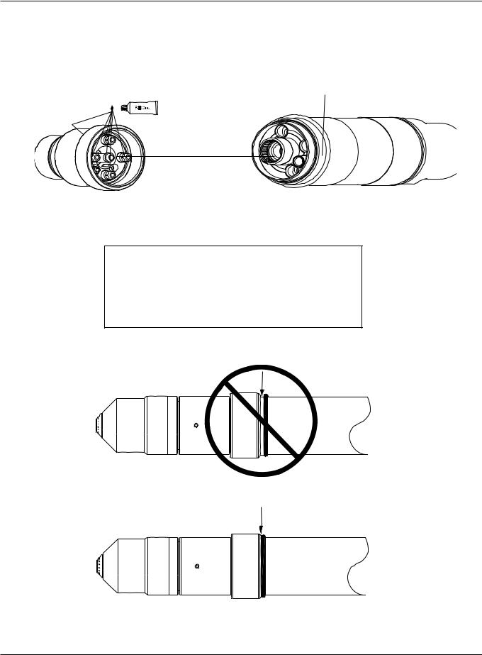
Connect the torch to the quick-disconnect
Apply a thin film of silicone to each o-ring
Torch body 220162
Apply a thin film of silicone to the threads on the quickdisconnect to ease torch installation.
Torch quick-disconnect receptacle 220163
Installation note
Align the torch body to the torch leads and secure by screwing completely together. Be certain that there is no space between the torch body and the o-ring on the torch leads. See also Ignition console connections earlier in this section for torch lead connections to ignition console.
HPR260 Auto Gas Instruction Manual |
3-31 |
0

INSTALLATION
Torch mounting and alignment
Mounting the torch
Securing screws
Torch sleeve
Torch mounting bracket
Installation note
1.Install the torch (with torch leads attached) in the torch mounting bracket.
2.Position the torch until the torch body extends all the way through the bracket, so that the bracket is now around the torch sleeve and not touching the torch body. Position the torch approximately 6 mm (0.25 in.) from the workpiece.
3.Tighten the securing screws.
0°
90°
Torch alignment
To align the torch at right angles to the workpiece, use a square at 0° and 90°. See figure above.
See also Changing consumables in Section 4 to install consumables in the torch.
Torch lifter requirement
The system requires a high-quality, motorized torch lifter with sufficient travel to cover all cutting thickness requirements. The lifter must provide 203 mm (8 in.) of vertical travel. The unit should have the capability of maintaining a constant speed of up to 5080 mm/min (200 ipm) with positive braking. A unit which drifts through the stop point is not acceptable.
3-32 |
HPR260 Auto Gas Instruction Manual |
0
INSTALLATION
Power requirements
General
All switches, slow-blow fuses and power cables are customer-supplied and must be chosen as outlined by applicable national or local electrical codes. Installation must be performed by a licensed electrician. Use a separate primary line disconnect switch for the power supply.
|
|
|
|
|
ESU F |
|
|
|
|
|
|
|
|
|
|
Recommended Cable size for 15 m |
|
Input |
|
Rated input current |
Recommended |
(50 feet) maximum length |
|
|
|
|
|||
Voltage |
Phase |
@ 45.5 kW output |
slow-blow fuse size |
Rated for 60°C |
Rated for 90°C |
|
|
|
|
|
|
200/208 VAC |
3 |
149/144 amps |
175 amps |
N/A |
67.5 mm2 (2/0 AWG) |
240 VAC |
3 |
124 amps |
150 amps |
107.2 mm2 (4/0 AWG) |
53.5 mm2 (1/0 AWG) |
400 VAC |
3 |
75 amps |
90 amps |
42.4 mm2 (1 AWG) |
26.7 mm2 (3 AWG) |
440 VAC |
3 |
68 amps |
80 amps |
42.4 mm2 (1 AWG) |
21.2 mm2 (4 AWG) |
480 VAC |
3 |
62 amps |
70 amps |
33.6 mm2 (2 AWG) |
21.2 mm2 (4 AWG) |
600 VAC |
3 |
50 amps |
60 amps |
26.7 mm2 (3 AWG) |
13.3 mm2 (6 AWG) |
Note: Cable AWG recommendations taken from table 310-16 of the National Electric
Code handbook (USA).
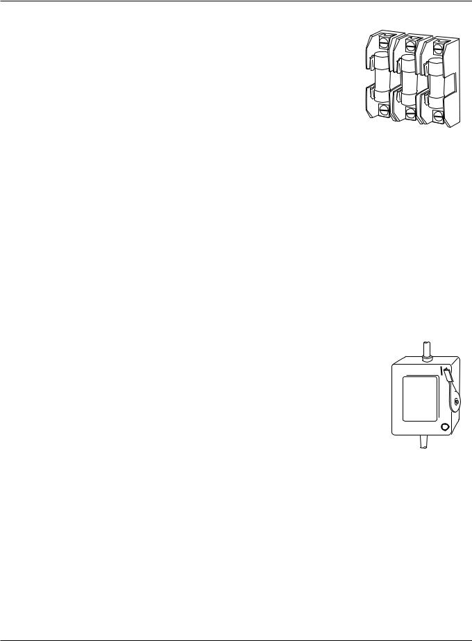
Line disconnect switch
The line disconnect switch serves as the supply-voltage disconnecting (isolating) device. Install this switch near the power supply for easy access by the operator.
Installation must be performed by a licensed electrician and according to applicable national or local codes.
The switch should:
•Isolate the electrical equipment and disconnect all live conductors from the supply voltage when in the “OFF” position
•Have one “OFF” and one “ON” position clearly marked with “O” (OFF) and “l” (ON)
•Have an external operating handle capable of being locked in the “OFF” position
•Contain a power-operated mechanism that serves as an emergency stop
•Have slow-blow fuses installed for the proper breaking capacity (see table above).
SWITCH BOX
Power cable
Wire sizes vary based on the distance of the receptacle from the main box. The wire sizes listed in the table above were taken from the National Electric Code 1990 handbook, table 310.16 (USA). Use a 4-conductor Type SO input power cable with a conductor temperature rating of 60° C (140° F). Installation must be performed by a licensed electrician.
HPR260 Auto Gas Instruction Manual |
3-33 |
1
INSTALLATION
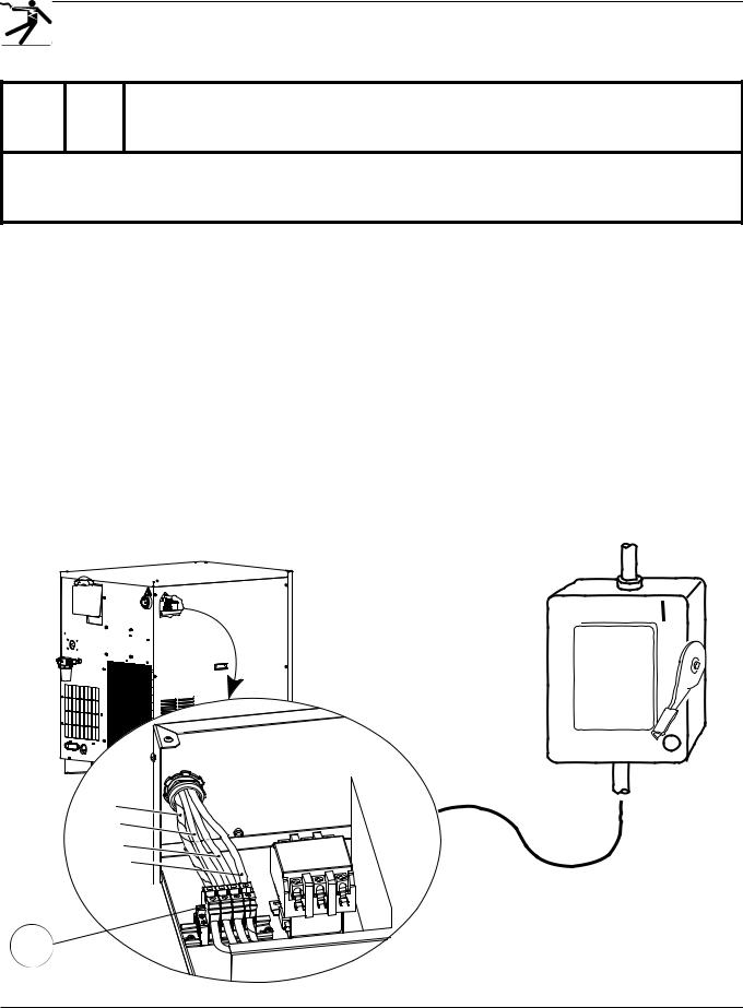
Connect the power
DANGER
ELECTRICAL SHOCK CAN KILL
The line disconnect switch must be in the OFF position before making the power cable connections. In the U.S., use a “lock-out/tag-out” procedure until installation is complete. In other countries, follow appropriate national or local safety procedures.
1.Insert the power cable through the strain relief at the rear of the power supply.
2.Connect the ground lead (PE) to the GROUND terminal of TB1 as shown below.
3.Connect the power leads to the terminals of TB1 as shown below.
4.Check that the line disconnect switch is in the OFF position and remains in the OFF position for the remainder of the installation of the system.
5.Connect the power cord leads to the line disconnect switch following national or local electrical codes.
North American wire colors |
European wire colors |
U = Black |
U = Black |
V = White |
V = Blue |
W = Red |
W = Brown |
(PE) Earth ground = Green/Yellow |
(PE) Earth ground = Green/Yellow |
Line disconnect switch
GND
W
V
U
Power
cable
TB1
3-34 |
HPR260 Auto Gas Instruction Manual |
0

INSTALLATION
Torch coolant requirements
The power supply is shipped without any coolant in the tank. Hypertherm recommends a mixture of 30% propylene glycol, 69.9% deionized water, and 0.1% benzotriazole. This mixture resists freezing to -12° C (+10° F) and contains a corrosion inhibitor to protect copper surfaces in the coolant loop. This mixture is available in 1-gallon (3.8 liter) containers by ordering 028872. 100% propylene glycol is available by ordering 028873.
Caution: For operating temperatures colder than the temperature stated above, the percentage of propylene glycol must be increased. Failure to do so could result in a cracked torch head, hoses or other damage to the torch coolant system due to freezing.
See Material Safety Data Sheets Appendix to determine if a stronger propylene glycol:purified water solution is needed for your particular application.
Observe the warning and cautions below. Refer to the Material Safety Data Sheets Appendix for data on safety, handling and storage of propylene glycol and benzotriazole.
WARNING
COOLANT CAN BE IRRITATING TO SKIN AND EYES AND
HARMFUL OR FATAL IF SWALLOWED
Propylene glycol and benzotriazole are irritating to skin and eyes, and harmful or fatal if swallowed. Upon contact, flush skin or eyes with water. If swallowed, drink water and call a physician immediately. Do not induce vomiting.
Caution: Always use propylene glycol in the coolant mixture. Do not use automotive anti-freeze in place of propylene glycol. Antifreeze contains corrosion inhibitors that will damage the torch coolant system.
Always use purified water in the coolant mixture in order to prevent damage to the pump and corrosion in the torch coolant system.
Water purity requirements
It is critical to maintain a low level of calcium carbonate in the coolant to avoid reduced performance of the torch or cooling system.
HPR260 Auto Gas Instruction Manual |
3-35 |
0
INSTALLATION
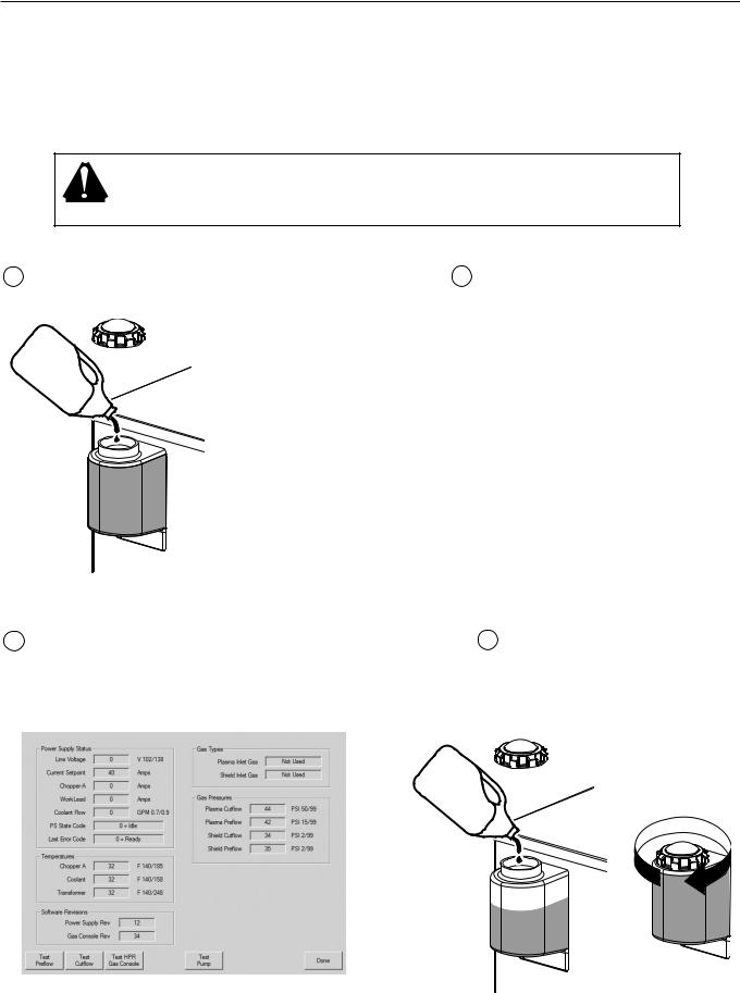
Fill the power supply with coolant
The system will take 11.4 – 15.1 liters (3 to 4 gallons) of coolant depending on the length of the torch leads and whether the system has a local or remote ignition console.
Caution: The coolant pump will be damaged if it is run with water only. See torch coolant requirements for proper coolant mixtures. Do not overfill coolant tank.
1Add coolant to the power supply until the tank is full.
2Turn ON the power supply using the remote ON/OFF switch or the CNC.
3Locate the CNC screen for manual pump control. The pump needs to run to fill the leads.
4Add coolant to the power supply until the tank is full and replace the filler cap.
|
|
|
|
|
|
3-36 |
|
HPR260 Auto Gas Instruction Manual |
0
INSTALLATION
Gas requirements
The customer must furnish all gases and gas-supply regulators for the system. Use a high-quality, 2-stage pressure regulator located within 3 m (10 ft) of the selection console. See gas regulators in this section for recommendations. See Section 2 for gas and flow specifications.
Caution: Gas supply pressures not within the specifications in Section 2 can cause poor cut quality, poor consumable life and operational problems.
If the purity level of the gas is too low (or too high in the case of methane) or if there are leaks in the supply hoses or connections,
•Cut speeds can decrease
•Cut quality can deteriorate
•Cutting thickness capability can decrease
•Parts life can shorten
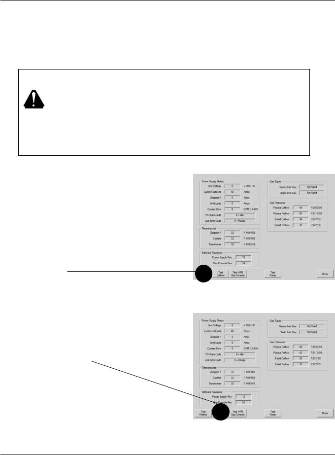
Setting the supply regulators
1.Make sure the power is OFF. Set all gas regulator pressures to 8 bar (115 psi).
2.Turn power ON using the remote ON/OFF switch or the CNC.
3.Set to test preflow.
4.While gas is flowing adjust the supply regulator for the shield gas pressure to 8 bar (115 psi)
5.Turn OFF test preflow.
6.Set system to test cut-flow.
7.While gas is flowing adjust the supply regulator for the plasma gas to 8 bar (115 psi).
8.Turn OFF test cutflow.
HPR260 Auto Gas Instruction Manual |
3-37 |
1