

HPR 260 Manual Instrution
.pdfMAINTENANCE
Selection console control PCB2
Control PCB2 firmware list
Item |
Part number |
|
|
|
|
|
|
U9 |
081096 EVEN |
|
|
U10 |
081096 ODD |
|
|
|
|
|
|
|
|
||
Selection console control board LED list |
|
||
LED |
Signal name |
Color |
|
|
|
|
|
D17 |
+ 3.3 VDC |
Green |
|
D18 |
+ 5 VDC |
Green |
|
D26 |
CAN - RX |
Green |
|
D27 |
CAN - TX |
Green |
|
D28 |
Not used |
Red |
|
D37 |
Not used |
Red |
|
D38 |
Not used |
Red |
|
D39 |
Not used |
Red |
|
D40 |
+ 15 VDC |
Green |
|
D45 |
+ 24 VDC |
Green |
|
|
|
|
|
|
|
|
|
5-30 |
|
|
HPR260 Auto Gas Instruction Manual |
0
MAINTENANCE
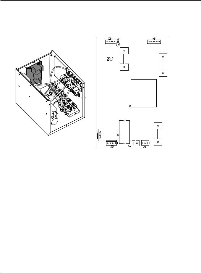
Selection console power distribution PCB1
LED |
Signal name |
Color |
D2 |
SV 16 |
Red |
D4 |
+ 5VDC |
Green |
|
|
|
HPR260 Auto Gas Instruction Manual |
5-31 |
0

MAINTENANCE
Selection console, AC valve-driver PCB3
LED |
Signal name |
Color |
LED |
Signal name |
Color |
D1 |
SV1 |
Red |
D11 |
SV11 |
Red |
D2 |
SV2 |
Red |
D12 |
SV12 |
Red |
D3 |
SV3 |
Red |
D13 |
SV13 |
Red |
D4 |
SV4 |
Red |
D14 |
SV14 |
Red |
D5 |
SV5 |
Red |
D15 |
Not used |
Red |
D6 |
SV6 |
Red |
D16 |
Metering console vent solenoid |
Red |
D7 |
SV7 |
Red |
D17 |
MV1 close |
Red |
D8 |
SV8 |
Red |
D18 |
MV1 open |
Red |
D9 |
SV9 |
Red |
D19 |
MV2 close |
Red |
D10 |
SV10 |
Red |
D20 |
MV2 open |
Red |
|
|
|
|
|
|
5-32 |
HPR260 Auto Gas Instruction Manual |
0

MAINTENANCE
Metering console control PCB
Control PCB2 firmware list
Item |
Part number |
|
|
|
|
|
|
U9 |
081096 EVEN |
|
|
U10 |
081096 ODD |
|
|
|
|
|
|
|
|
||
Metering console control board LED list |
|
||
LED |
Signal name |
Color |
|
|
|
|
|
D17 |
+ 3.3 VDC |
Green |
|
D18 |
+ 5 VDC |
Green |
|
D26 |
CAN - RX |
Green |
|
D27 |
CAN - TX |
Green |
|
D28 |
Burkert valve 2 |
Red |
|
D37 |
Burkert valve 1 |
Red |
|
D38 |
Burkert valve 4 |
Red |
|
D39 |
Burkert valve 3 |
Red |
|
D40 |
+ 15 VDC |
Green |
|
D45 |
+ 24 VDC |
Green |
|
|
|
||
|
|
|
|
HPR260 Auto Gas Instruction Manual |
5-33 |
||
0
MAINTENANCE
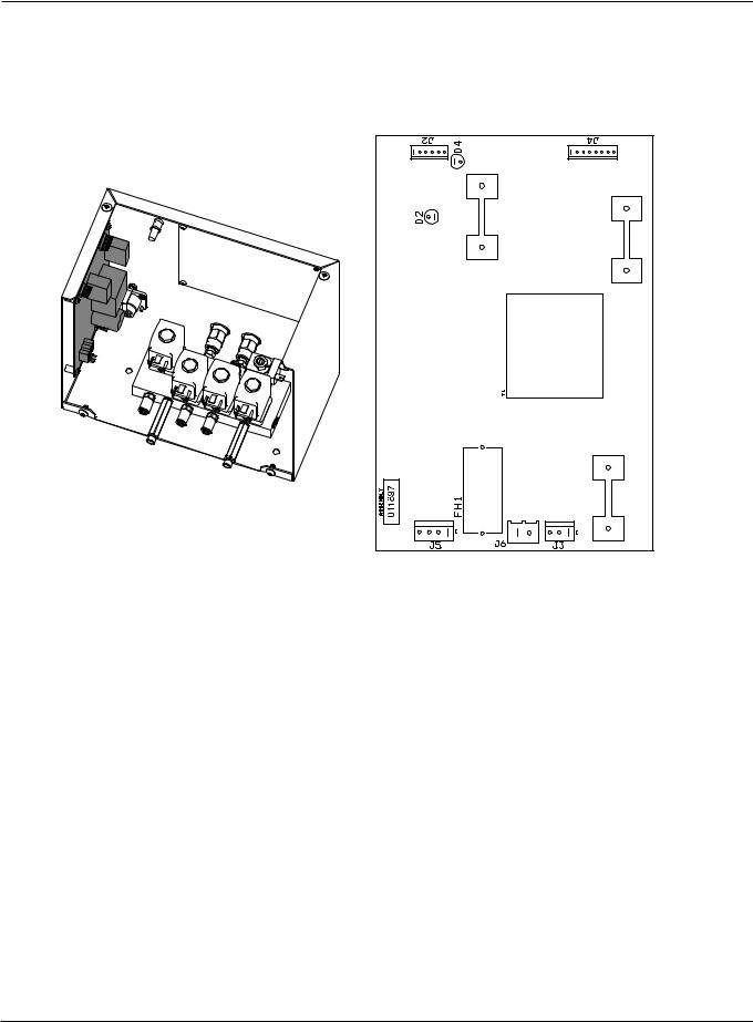
Metering console power distribution PCB
LED |
Signal name |
Color |
D2 |
SV 16 |
Red |
D4 |
+ 5VDC |
Green |
|
|
|
5-34 |
HPR260 Auto Gas Instruction Manual |
0

MAINTENANCE
Chopper module test procedure
WARNING
SHOCK HAZARD: Use extreme care when working near the chopper modules. The large electrolytic capacitor(s) (blue-cased cylinder(s) store large amounts of energy in the form of electric voltage. Even if the power is off, dangerous voltages exist at the capacitor terminals, on the chopper, and the diode heatsinks. Never discharge any capacitor with a screwdriver or other implement … explosion, property damage and/or personal injury will result.
Note: Read voltages with a digital multimeter (DVM) capable of storing minimum and maximum readings.
1.Turn OFF all power to the system. Disconnect the 2 terminals (wire colors red and red/black) on the line filter (FLTR1) in the ignition console. This will disable the highvoltage transformer (T1).
2. Remove large fuse F3 (left side of power supply). Check to see if fuse is blown.
Note: The 150A fuse is connected to the positive lead. Disconnecting the fuse does not prevent DC voltage from being present at the electrode.
3.Place the positive lead of the DVM on the (+) side of the input rectifier and the negative lead on the (-) side of the input rectifier. See the figure on next page. Note that actual connection points are hidden by the capacitor support bracket in figure.
4.Turn ON power to the system, and start the system. After the START command has been given, measure voltage. The input to the chopper at the points described in step 3 should be about +311 VDC. If the input is OK and the corresponding fuse (F3) is blown, replace the chopper module. If there is no +311 VDC input, verify the 3-phase AC input to the chopper. Also, verify the main contactor (CON1) contacts, connections and associated wiring. Repair or replace any defective components. To check AC voltage to chopper, perform the same test again with the DVM in AC mode. Check voltage between A - B, B - C and A - C. The voltage should be 220 VAC.
5.If voltage from step 4 is +311 VDC and the fuse (F3) is not blown, verify the chopper(s) output.
CH1: • Place the positive lead of the DVM on point (+) WORK on the chopper module (wire #39) and negative lead on point (-) TORCH (wire #38). See the figure on the next page.
•Turn ON the system and give the START command. After the START command has been given measure the voltage. If the output from these points is greater than 311 VDC, the chopper may be OK. If the voltage is lower than 311 VDC, replace the chopper.
•If the voltage is 311 VDC, re-install the fuse (F3) and measure the voltage as above. A low voltage reading with this method means either an external short or faulty chopper.
•Verify that the error code number is 020 (no pilot arc sensed) and replace chopper.
HPR260 Auto Gas Instruction Manual |
5-35 |
0

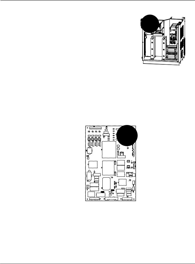
MAINTENANCE
6.If the chopper does not output +311 VDC, verify that LED2 and D2 are illuminated. If they are extinguished, verify that 120 V is going to JP9.6, pins 1 and 2, on the chopper. If there is not 120 V at JP9.6, inspect the wiring to the power distribution board. Repair or replace any defective component. Also verify that LED1 is illuminated when START command is given. If LED1 is not illuminated when the START signal is given, then verify that J9.1 is seated properly to chopper. Inspect wiring from J9.1 to control board. Replace control board if the wiring and connections are OK.
7.If a chopper still does not output +311 VDC after completing these instructions, replace the chopper.
Input bridge (3-phase AC input)
Input rectifier
LED1 |
LED2 |
D2 |
Chopper module – front view
5-36 |
HPR260 Auto Gas Instruction Manual |
0
MAINTENANCE
Phase-loss detection test
1. Turn OFF all power to the system and remove the cover from CON1.
2.Inspect the condition of the 3 contacts for excessive wear. If one of more of the contacts are worn excessively, replace CON1 and restart the system. If the error remains, perform the following steps.
OK |
Excessive wear |
3. Test the fuses F5, F6, and F7 on the power distribution board (PCB2). If any of the fuses are blown, replace PCB2.
4.Remove J2.8 from PCB2 and place a jumper between pins 1 and 2 on the cable connector.
a.Make a test cut. If the phase-loss error continues, verify wiring between J2.8 on PCB2 and J3.302 on PCB3 by verifying the continuity between
–J2.8 pin1 to J3.302 pin14
–J2.8 pin2 to J3.302 pin15.
b.If the wiring is ok, replace PCB3. If any wiring is damaged, repair or replace any damaged wires.
c.If the phase-loss error goes away while the jumper is on J2.8, make another cut and measure the phase- to-phase voltage across the fuses F5, F6, and F7. The voltage should be 220 VAC +/-15%. If one of the 3 voltage readings is less than 187 VAC, check the contacts to the contactor, and check for loose connections between the power cord, contactor, power transformer – and the chopper.
HPR260 Auto Gas Instruction Manual |
5-37 |
0
MAINTENANCE
WARNING
SHOCK HAZARD: Always use caution when servicing a power supply when plugged in and the covers are removed. Dangerous voltages exist within the power supply which could cause injury or death.
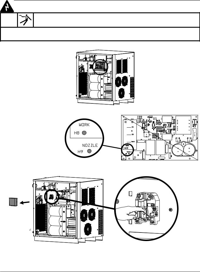
Torch lead test
1. Turn OFF all power to the system.
2. Locate the start-circuit assembly.
3.Install a temporary jumper wire between H8 (work) and H9 (nozzle) on the start
circuit PCB1.
041811
4. Locate the pilot arc relay (CR1) and remove the dust cover. Have a second person close the contact.
5.Measure the ohm value between the nozzle and the plate. The reading should be less than 3 ohms. A measurement of greater than 3 ohms indicates a faulty connection between the torch and ignition console or between the ignition console and the power supply.
6.Verify that the pilot arc wire on the torch lead is not damaged. If it is damaged replace the lead. If it is not damaged replace the torch head.
5-38 |
HPR260 Auto Gas Instruction Manual |
0

MAINTENANCE
Preventive maintenance
Introduction
Deteriorating consumable parts life is one of the first indications that something is wrong with a plasma system. Reduced parts life increases operating costs in two ways: the operator must use more electrodes and nozzles to cut the same amount of metal, and the work of cutting must stop more often to change consumables.
Proper maintenance often eliminates the problems that shorten the life of consumable parts. Since labor and overhead can account for 80% of the cost of cutting, improved productivity can reduce cutting costs dramatically.
Preventive maintenance protocol
The following protocol covers the basic elements of all Hypertherm HyPerformance plasma systems.
If inspection suggests that a component is worn and might require replacement, and you would like confirmation of your decision, please contact Hypertherm's Technical Service department.
The power supply
WARNING
ELECTRIC SHOCK CAN KILL
Turn off all electrical power before removing the power supply cover and set the line disconnect switch to OFF. In the U.S., use a “lock-out and tag-out” procedure until the service or maintenance is complete. In other countries, follow appropriate local or national safety procedures.
1.With power to the power supply turned off, remove all side panels. Use compressed air to blow out any accumulation of dust and particulates.
2.Inspect wiring harnesses and connections for wear, damage or loose connections. If you see any discoloration that might indicate overheating, contact Hypertherm Technical Service.
3.Inspect the main contactor for excessive pitting on the contacts, characterized by a blackened, rough surface on any of the contacts. If this condition exists, replacement is recommended.
4.Inspect the pilot arc relay (CR1) for excessive pitting on the contacts, characterized by a roughened, black surface. Replace if necessary.
HPR260 Auto Gas Instruction Manual |
5-39 |
0