

HPR 260 Manual Instrution
.pdfINSTALLATION
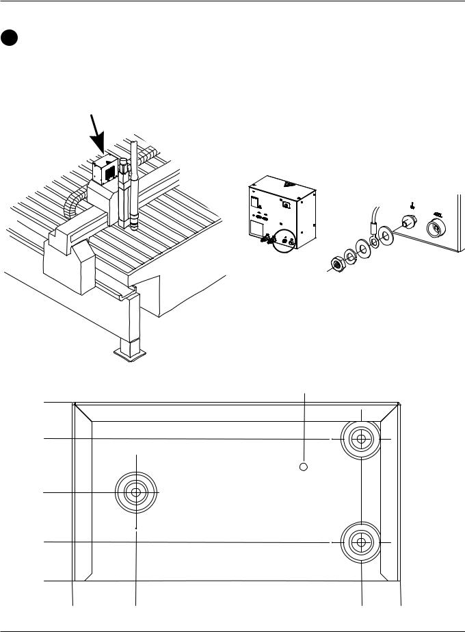
Metering console
(PE)
Selection console
(PE)
Plasma power supply
Ignition console
(PE)
(PE) |
Ferrite choke |
Power cord ground
Work table
Supplementary
grounding rod
Figure 2 Alternate ground connection configuration
The preferred cable routing for this configuration is as shown, but it is acceptable to “daisy-chain” the grounds for the selection console and other equipment to the ignition console. The ignition console should NOT be daisychained through the other components to the work table.
3-8 |
HPR260 Auto Gas Instruction Manual |
0

INSTALLATION
APlacement of the power supply
DANGER
ELECTRICAL SHOCK CAN KILL
Remove all electrical connections to power supply before moving or positioning. Transporting unit can cause personal injury and equipment damage.
The power supply can be moved by forklift but the forks must be long enough to extend the entire length of the base. Take care when lifting so that the underside of the power supply is not damaged.
•Place the power supply in an area that is free of excessive moisture, has proper ventilation and is relatively clean. Allow room at the sides and rear of the power supply for servicing.
•Cooling air is drawn in through the front panel and is exhausted through the rear of the unit by a cooling fan. Do not place any filter device over the air intake locations, which reduces cooling efficiency and VOIDS THE WARRANTY.
HPR260 Auto Gas Instruction Manual |
3-9 |
0

INSTALLATION
BInstall the ignition console
•Mount the ignition console on the gantry (bridge) for the RHF configuration.
•Mount the ignition console on the power supply for the LHF configuration.
•Allow room to remove the top for servicing.
32 mm |
184 mm |
1.25" |
7.25" |
216 mm 8.50"
32 mm 1.25"
248 mm
9.75"
279 mm
11.00" 7 mm
.028" 

 (4 places)
Ignition console grounding
3-10 |
HPR260 Auto Gas Instruction Manual |
0

INSTALLATION
Horizontal RHF mounting
Vertical RHF mounting
LHF mounting
HPR260 Auto Gas Instruction Manual |
3-11 |
0

INSTALLATION
CPlacement of the selection console
•Position the selection console near the cutting table. Allow room to remove the top and right side cover for servicing. Preferred orientation is shown in the figure below. The maximum length of cables between the power supply and selection console is 45 m (150 ft). The maximum length of cables and hoses between the selection console and the metering console assembly is 15 m (50 ft).
Preferred selection console orientation
Selection console grounding
314.5 mm 12.38"
38.1 mm 1.5"
0 |
|
|
0 |
76.2 mm |
254.0 mm |
|
3.0" |
10.0" |
3-12 HPR260 Auto Gas Instruction Manual
0
INSTALLATION
DInstall the metering console
•Mount the metering console near the torch lifter station. The maximum length of the gas hoses between the metering console and the torch is 1.8 m (6 ft).
Metering console grounding
Vent hole. Do not block.
153.9 mm 6.1"
122.2 mm
4.8"
76.2 mm 3.0"
33.3 mm
1.3"
0 |
|
|
|
0 |
54.9 mm |
248.9 mm |
282.5 mm |
|
2.2" |
9.8" |
11.1" |
HPR260 Auto Gas Instruction Manual |
|
3-13 |
|
0

INSTALLATION
Power supply to ignition console leads
1 Pilot arc lead
Ignition console |
|
|
I/O board |
Part no. |
Length |
Part no. |
Length |
123683 |
1.5 m (5 ft) |
123823 |
20 m (65 ft) |
123820 |
3 m (10 ft) |
123735 |
25 m (82 ft) |
123821 |
4.5 m (15 ft) |
123668 |
35 m (115 ft) |
123666 |
7.5 m (25 ft) |
123669 |
45 m (150 ft) |
123822 |
10 m (35 ft) |
123824 |
60 m (200 ft) |
123667 |
15 m (50 ft) |
123825 |
75 m (250 ft) |
2 Negative lead
|
Ignition console |
|
Power supply |
Part no. |
Length |
Part no. |
Length |
123829 |
1.5 m (5 ft) |
123819 |
20 m (65 ft) |
123816 |
3 m (10 ft) |
123775 |
25 m (82 ft) |
123817 |
4.5 m (15 ft) |
123776 |
35 m (115 ft) |
123773 |
7.5 m (25 ft) |
123777 |
45 m (150 ft) |
123818 |
10 m (35 ft) |
123771 |
60 m (200 ft) |
123774 |
15 m (50 ft) |
123772 |
75 m (250 ft) |
Pilot arc lead
Negative lead
3-14 |
HPR260 Auto Gas Instruction Manual |
0

INSTALLATION
Work lead |
2 |
1 |
|
Negative lead |
Pilot arc lead |
1
Pilot arc lead
2
Negative lead
HPR260 Auto Gas Instruction Manual |
3-15 |
0

INSTALLATION
3Ignition control cable
|
|
|
|
|
|
|
|
|
|
|
|
Part no. |
Length |
Part no. |
Length |
||
|
|
|
|
||
123684 |
1.5 m (5 ft) |
123736 |
25 m (82 ft) |
||
123834 |
4.5 m (15 ft) |
123672 |
35 m (115 ft) |
||
123670 |
7.5 m (25 ft) |
123673 |
45 m (150 ft) |
||
123835 |
10 m (35 ft) |
123837 |
60 m (200 ft) |
||
123671 |
15 m (50 ft) |
123838 |
75 m (250 ft) |
||
123836 |
20 m (65 ft) |
|
|
|
|
|
|
|
|
|
|
CABLE SIGNAL LIST – power supply to ignition console
Power supply end |
Ignition console end |
||||
Pin # I/O |
Description |
Pin # I/O Function |
|||
|
|
|
|
|
|
1 |
|
120Vac Hot |
1 |
|
|
|
|
|
|
|
|
2 |
|
120Vac Return |
2 |
|
|
|
|
|
|
|
|
3 |
|
Ground |
3 |
|
|
|
|
|
|
|
|
4 |
|
Not connected |
4 |
|
|
|
|
|
|
|
|
3
3-16 |
HPR260 Auto Gas Instruction Manual |
0

INSTALLATION
4Ignition console coolant hoses
Red
Green
Part no. |
Length |
|
|
|
|
128499 |
1.5 m (4.33 ft) |
|
028441 |
7.5 m (25 ft) |
|
028442 |
15 m (50 ft) |
4 |
128984 |
20 m (65 ft) |
|
128078 |
25 m (82 ft) |
|
028896 |
35 m (115 ft) |
|
028445 |
45.5 m (150 ft) |
|
128985 |
75 m (250 ft) |
|
|
|
|
Red
Green
HPR260 Auto Gas Instruction Manual |
3-17 |
0