

HPR 260 Manual Instrution
.pdfSPECIFICATIONS
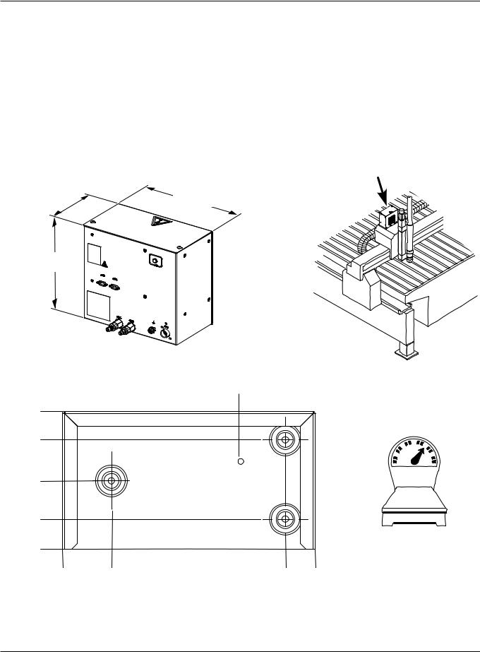
Selection console – 078185
•Maximum cable length from the power supply to the selection console is 46 m (150 ft).
•Maximum cable length from the selection console to the metering console is 15 m (50 ft).
•Position the selection console on top of the power supply or near the CNC on the cutting table. Allow room to open the top for servicing.
285.75 mm |
355.6 mm |
11.25" |
14.00" |
311.15 mm 12.25"
13.6 kg
30 lb
314.5 mm 12.38"
38.1mm
1.5"
0 |
|
|
0 |
76.2 mm |
254.0 mm |
|
3.0" |
10.0" |
2-8 |
|
HPR260 Auto Gas Instruction Manual |
0
SPECIFICATIONS
Metering console – 078184
•Maximum cable length from the metering console to the torch lifter station is 1.8 m (6 ft).
•Mount the metering console to the torch carriage on larger tables. On smaller tables it can be mounted to a bracket just above the bridge.
155.58 mm
6.125"
263.53 mm
10.375"
153.9mm 6.1"
122.2mm 4.8"
76.2mm 3.0"
33.3mm 1.3"
0
0
285.75 mm 11.25"
Vent hole. Do not block.
6.4 kg
14 lb
54.9 mm |
248.9 mm |
282.5 mm |
2.2" |
9.8" |
11.1" |
HPR260 Auto Gas Instruction Manual |
2-9 |
0

SPECIFICATIONS
Torch – 128818
• The outside diameter of the torch mounting sleeve is 50.8 mm (2.0 in.)
1.8 m
6'
|
|
27 mm |
|
|
|
1.07" |
|
193 mm |
|
116 mm |
|
7.59" |
|
4.55" |
48 mm |
|
|
|
|
|
|
|
1.89" |
51 mm |
57 mm |
|
51 mm |
2.00" |
2.25" |
|
2.00" |
107 mm 4.22"
336 mm
13.21"
2.11kg
4.65lb
2-10 |
HPR260 Auto Gas Instruction Manual |
0
|
Section 3 |
|
INSTALLATION |
|
|
In this section: |
|
Upon receipt ............................................................................................................................................................. |
3-3 |
Claims....................................................................................................................................................................... |
3-3 |
Installation requirements........................................................................................................................................... |
3-3 |
Noise levels .............................................................................................................................................................. |
3-3 |
Placement of system components............................................................................................................................ |
3-3 |
Torque specifications........................................................................................................................................ |
3-3 |
Installation requirements........................................................................................................................................... |
3-4 |
System components......................................................................................................................................... |
3-5 |
Cables and hoses ............................................................................................................................................ |
3-5 |
Supply gas hoses............................................................................................................................................. |
3-5 |
Customer supplied power cable....................................................................................................................... |
3-5 |
System grounding requirements............................................................................................................................... |
3-6 |
Suggested ground cable routing............................................................................................................................... |
3-6 |
Power supply.................................................................................................................................................... |
3-6 |
Equipment grounding ....................................................................................................................................... |
3-6 |
Work table grounding ....................................................................................................................................... |
3-7 |
Placement of the power supply ........................................................................................................................ |
3-9 |
Install the ignition console .............................................................................................................................. |
3-10 |
Placement of the selection console................................................................................................................ |
3-12 |
Install the metering console ........................................................................................................................... |
3-13 |
Power supply to ignition console leads................................................................................................................... |
3-14 |
Pilot arc lead .................................................................................................................................................. |
3-14 |
Negative lead ................................................................................................................................................. |
3-14 |
Ignition control cable ...................................................................................................................................... |
3-16 |
Ignition console coolant hoses ....................................................................................................................... |
3-17 |
Power supply to selection console cables .............................................................................................................. |
3-18 |
Control cable .................................................................................................................................................. |
3-18 |
Power cable ................................................................................................................................................... |
3-18 |
Selection console to metering console connections ............................................................................................... |
3-20 |
Cable and gas hose assembly ....................................................................................................................... |
3-20 |
Power supply to CNC interface cable ..................................................................................................................... |
3-22 |
Optional multi-system CNC interface cable ................................................................................................... |
3-22 |
Notes to CNC interface cable run list ............................................................................................................. |
3-23 |
Examples of output circuits ............................................................................................................................ |
3-24 |
Examples of input circuits .............................................................................................................................. |
3-25 |
Remote on/off switch .............................................................................................................................................. |
3-26 |
Torch lead assembly ............................................................................................................................................... |
3-27 |
Work lead................................................................................................................................................................ |
3-28 |
Torch connections................................................................................................................................................... |
3-29 |
Connect the torch to the torch lead assembly................................................................................................ |
3-29 |
|
|
HPR260 Auto Gas Instruction Manual |
3-1 |
0

INSTALLATION
Connect the torch to the quick-disconnect ..................................................................................................... |
3-31 |
Torch mounting and alignment................................................................................................................................ |
3-32 |
Mounting the torch ......................................................................................................................................... |
3-32 |
Torch alignment.............................................................................................................................................. |
3-32 |
Torch lifter requirement ........................................................................................................................................... |
3-32 |
Power requirements................................................................................................................................................ |
3-33 |
General .......................................................................................................................................................... |
3-33 |
Line disconnect switch ................................................................................................................................... |
3-33 |
Power cable ................................................................................................................................................... |
3-33 |
Connect the power.................................................................................................................................................. |
3-34 |
Torch coolant requirements .................................................................................................................................... |
3-35 |
Water purity requirements....................................................................................................................................... |
3-35 |
Fill the power supply with coolant ........................................................................................................................... |
3-36 |
Gas requirements ................................................................................................................................................... |
3-37 |
Setting the supply regulators.......................................................................................................................... |
3-37 |
Gas regulators ........................................................................................................................................................ |
3-38 |
Supply gas plumbing .............................................................................................................................................. |
3-39 |
Connect the supply gases.............................................................................................................................. |
3-39 |
Supply gas hoses ................................................................................................................................................... |
3-40 |
3-2 |
HPR260 Auto Gas Instruction Manual |
0

INSTALLATION
Upon receipt
•Verify that all system components on your order have been received. Contact your supplier if any items are missing.
•Inspect the system components for any physical damage that may have occurred during shipping. If there is evidence of damage, refer to Claims. All communications regarding claims must include the model number and serial number located on the back of the power supply.
Claims
Claims for damage during shipment – If your unit was damaged during shipment, you must file a claim with the carrier. Hypertherm will furnish you with a copy of the bill of lading upon request. If you need additional assistance, call Customer Service listed in the front of this manual, or your authorized Hypertherm distributor.
Claims for defective or missing merchandise – If any of the merchandise is defective or missing, contact your supplier. If you need additional assistance, call Customer Service listed in the front of this manual, or your authorized Hypertherm distributor.
Installation requirements
All installation and service of the electrical and plumbing systems must conform to national or local electrical and plumbing codes. This work should be performed only by qualified, licensed personnel.
Direct any technical questions to the nearest Hypertherm Technical Service Department listed in the front of this manual, or your authorized Hypertherm distributor.
Noise levels
Acceptable noise levels as defined by national or local codes may be exceeded by this plasma system. Always wear proper ear protection when cutting or gouging. See also Noise protection in the Safety section of this manual.
Data was taken while cutting 12.7 mm (0.5 in) mild steel at 260A using an O2 /Air process 76.2 mm (3 in) above water. The decibel readings at 914.4 mm (36 in) from the front of the torch and 330.2 mm (13 in) above the arc are: 120.7 Max Level, dBC (MaxP) and 98.6 Lav5, dBA.
Placement of system components
•Place all system components in position prior to making electrical, gas and interface connections. Use the diagram in this section for component placement guidelines.
•Ground all system components to earth. See System grounding requirements in this section for details.
•To prevent leaks in the system, tighten all gas and water connections as shown below:
Torque specifications
Gas or water |
|
|
|
hose size |
kgf-cm |
lbf-in |
lbf-ft |
|
|
|
|
Up to 10 mm (3/8") |
8.6-9.8 |
75-85 |
6.25-7 |
12 mm (1/2") |
41.5-55 |
360-480 |
30-40 |
2WRENCHES
• Do not place the power supply on an incline greater than 10° to prevent it from toppling.
HPR260 Auto Gas Instruction Manual |
3-3 |
0
INSTALLATION
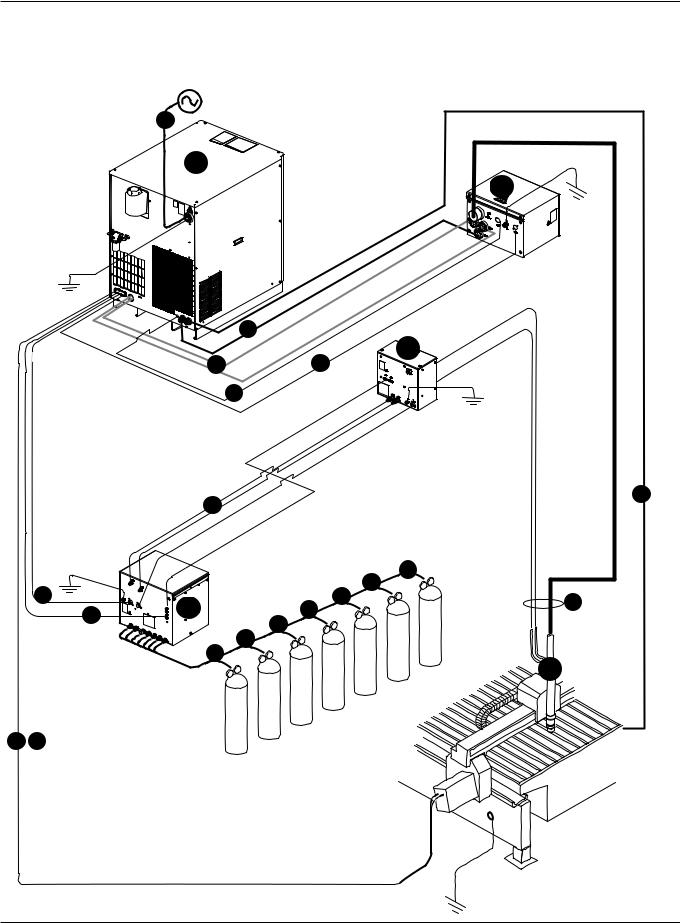
Installation requirements
19
A
B
2
D
43
1
11
7
|
|
|
|
18 |
|
6 |
|
|
16 |
17 |
|
C |
15 |
10 |
|||
5 |
|
||||
|
|
||||
|
14 |
|
|
||
|
|
|
|
||
|
|
13 |
|
|
|
|
|
12 |
|
|
E
8 9
3-4 |
HPR260 Auto Gas Instruction Manual |
0

INSTALLATION
System components
A
B
C
D
E
Power supply
Ignition console
Selection console
Metering console
Torch
Cables and hoses
1Pilot arc lead
2Negative lead
3Ignition control cable
4Ignition console coolant hoses
5Gas control cable
6Gas power cable
7Selection console to metering console hose and lead assembly
8CNC interface cable
9Optional CNC interface cable for systems with multiple power supplies
10Torch lead assembly
11Work lead
Supply gas hoses
12Oxygen
13Nitrogen
14Air
15Argon-hydrogen (H5)
16Argon-hydrogen (H35)
17Nitrogen-hydrogen (F5)
18Methane (CH4)
Customer-supplied power cable
19 Main power cable
HPR260 Auto Gas Instruction Manual |
3-5 |
0

INSTALLATION
System grounding requirements
The plasma system must be grounded for safety reasons and to suppress electromagnetic interference (EMI):
•Safety The entire system – power supply, accessory enclosures, and worktable – must be grounded to protect it and the operator from a ground fault. The protective earth (PE) ground connections must be installed by a licensed electrician and conform to national or local codes.
•EMI Suppression If allowed by national or local codes, the ground system can also be used to suppress EMI. Below is a guide to configure the plasma system for minimal EMI. See Electromagnetic Compatibility in this manual for additional information.
Suggested ground cable routing
Power supply
Connect the power supply to the PE ground terminal, using a properly sized color-coded conductor. This PE ground is connected to the service ground through the line disconnect switch. See the Installation section for further information on the power cord and the line disconnect switch.
Equipment grounding
All accessory modules that receive power from the plasma power supply must also use the power supply’s ground – either by connection to the PE terminal on the power supply, or by direct connection to the equipment ground conductor. Each module should have only one connection to ground to avoid ground loops and stray currents. If any enclosure is grounded to the work table, the work table must be grounded to the power supply.
Effective grounding for EMI reduction is highly dependent upon the installation configuration. Two acceptable configurations are shown in figures 1 and 2.
The ignition console should be installed near the work table, and grounded directly to it when mounted remotely. A locally mounted Ignition console (mounted on the power supply) is grounded directly to the power supply. Other modules should be installed near the power supply, and grounded directly to it (figure 1).
All modules may also be installed near the work table, and grounded directly to it (figure 2). Do not ground a remotely located ignition console directly to the power supply.
The customer must furnish all conductors for equipment grounding. Grounding conductors may be purchased through Hypertherm in any length specified by the customer (Part No. 047058). The conductor may also be purchased locally, using a minimum 8 AWG UL Type MTW cable (USA specification) or the appropriate cable specified by national and local codes.
Consult the appropriate manufacturer’s instructions to ground equipment that does not receive power from the power supply.
3-6 |
HPR260 Auto Gas Instruction Manual |
0

INSTALLATION
Work table grounding
If a supplementary ground rod is installed near the worktable to reduce EMI, it must be connected directly to the PE ground of the building structure, connected to the service ground; or to earth, providing the resistance between the ground rod and the service ground meets national or local codes. Place the supplementary ground rod within 6 m (20 ft) of the worktable according to national or local codes.
If any module is grounded to the work table, the work table must be grounded to the power supply, or the configuration must be changed to comply with applicable national and local electrical codes.
A ferrite choke can be placed in the conductor between the work table ground rod and the PE ground, with a number of turns through the choke to isolate the safety ground (at 60 Hz) from any electromagnetic interference (frequencies above 150 Khz). The more turns the better. A suitable ferrite choke can be made by wrapping 10 turns or more of the ground lead through Magnetics part number 77109-A7, Fair-Rite part number 59-77011101, or other equivalent ferrite choke. Locate the choke as close as possible to the plasma power supply.
|
|
|
|
|
|
Plasma power supply |
|
|
|
|
|
|
|
|
|
|
|
|
|
Ignition console |
|||||||||||||||||
|
|
|
|
|
|
|
|
|
|
|
|
|
|
|
|
|
|
|
|
|
|
|
|
|
|
|
|
|
|
|
(PE) |
||||||
Power cord |
|
(PE) |
Ferrite choke |
|
|
|
|
|
|
|
|
|
|
|
|
||||||||||||||||||||||
|
|
|
|
|
|
|
|
|
|
|
|
|
|||||||||||||||||||||||||
|
|
|
|
|
|
|
|
|
|
||||||||||||||||||||||||||||
|
|
|
|
|
|
|
|
|
|||||||||||||||||||||||||||||
|
|
|
|
|
|
|
|
|
|
|
|
|
|
|
|
|
|
|
|
|
|
|
|
|
|
|
|
|
|
|
|
|
|
|
|
|
|
|
|
|
|
|
|
|
|
|
|
|
|
|
|
|
|
|
|
|
|
|
|
|
|
|
|
|
|
|
|
|
|
|
|
|
|
|
|
|
|
|
|
|
|
|
|
|
|
|
|
|
|
|
|
|
|
|
|
|
|
|
|
|
|
|
|
|
|
|
|
|
|
|
|
|
|
|
|
|
|
|
|
|
|
|
|
|
|
|
|
|
|
|
|
|
|
|
|
|
|
|
|
|
|
|
|
|
|
|
|
|
|
||
ground |
|
|
|
|
|
|
|
|
|
|
|
|
|
|
|
|
|
|
|
|
|
|
|
|
|
|
|
|
|
|
|
|
|
|
|
|
|
|
|
|
|
|
|
|
|
|
|
|
|
|
|
|
|
|
|
|
|
|
|
|
|
|
|
|
|
|
|
|
|
|
Work table |
||||
|
|
|
|
|
|
|
|
|
|
|
|
|
|
|
|
|
|
|
|
|
|
|
|
|
|
|
|
|
|
|
|
|
|
|
|||
|
|
|
|
|
|
|
|
|
|
|
|
|
|
|
|
|
|
|
|
|
|
|
|
|
|
|
|
|
|
|
|
|
|
|
|
|
|
|
|
|
|
|
|
|
|
|
|
|
|
|
|
|
|
|
|
|
|
|
|
|
|
|
|
|
|
|
|
|
|
|
|
|
|
|
|
|
|
|
|
|
|
|
|
|
|
|
|
|
|
|
|
|
|
|
|
|
|
|
|
|
|
|
|
|
|
|
|
|
|
|
|
|
|
|
|
|
|
|
|
|
|
|
|
Selection console |
|
|
|
|
|
|
|
|
|
|
|
|
|
|
|
|
|
|
|
|
|||||||
|
|
|
|
|
|
|
|
|
|
|
(PE) |
|
|
|
|
|
|
|
|
|
|
|
|
|
|
|
|
|
|
|
|
||||||
|
|
|
|
|
|
|
|
|
|
|
|
|
|
|
|
|
|
|
|
|
|
|
|
|
|
|
|
|
|
|
|||||||
|
|
|
|
|
|
|
|
|
|
|
|
|
|
|
|
|
|
|
|
|
|
|
|
|
|
|
|
|
|
|
|||||||
|
|
|
|
|
|
|
|
|
|
|
|
|
|
|
|
|
|
|
|
|
|
|
|
|
|
|
|
|
|
|
|||||||
|
|
|
|
|
|
|
|
|
|
|
|
|
|
|
|
|
|
|
|
|
|
|
|
|
|
|
|
|
|
|
|||||||
|
|
|
|
|
|
|
|
|
|
|
|
|
|
|
|
|
|
|
|
|
|
|
|
|
|
|
|
Supplementary |
|||||||||
|
|
|
|
|
|
|
|
|
|
|
|
|
|
|
|
|
|
|
|
|
|
|
|
|
|
|
|
||||||||||
|
|
|
|
|
|
|
|
|
|
|
|
|
|
|
|
|
|
|
|
|
|
|
|
|
|
|
|
||||||||||
|
|
|
|
|
|
|
|
|
|
|
|
|
|
|
|
|
|
|
|
|
|
|
|
|
|
|
|
||||||||||
|
|
|
|
|
|
|
|
|
|
|
|
|
|
|
|
|
|
|
|
|
|
|
|
|
|
|
|
||||||||||
|
|
|
|
|
|
|
|
|
|
|
|
|
|
|
|
|
|
||||||||||||||||||||
|
|
|
|
|
|
|
|
|
|
|
|
|
|
|
|
|
|
|
|
|
|
|
|
|
|
|
|
grounding rod |
|||||||||
|
|
|
|
|
|
|
|
|
|
Metering console |
|||||||||||||||||||||||||||
|
|
|
|
|
|
|
|
|
|
|
|
|
|
|
|
|
|
|
|
|
|
|
|
|
|
|
|
|
|
||||||||
|
|
|
|
|
|
|
|
|
|
|
(PE) |
|
|
|
|
|
|
|
|
|
|
|
|
|
|
|
|
|
|
|
|
||||||
|
|
|
|
|
|
|
|
|
|
|
|
|
|
|
|
|
|
|
|
|
|
|
|
|
|
|
|
|
|
|
|||||||
|
|
|
|
|
|
|
|
|
|
|
|
|
|
|
|
|
|
|
|
|
|
|
|
|
|
|
|
|
|
|
|||||||
|
|
|
|
|
|
|
|
|
|
|
|
|
|
|
|
|
|
|
|
|
|
|
|
|
|
|
|
|
|
|
|||||||
|
|
|
|
|
|
|
|
|
|
|
|
|
|
|
|
|
|
|
|
|
|
|
|
|
|
|
|
|
|
|
|
|
|
|
|
|
|
|
|
|
|
|
|
|
|
|
|
|
|
|
|
|
|
|
|
|
|
|
|
|
|
|
|
|
|
|
|
|
|
|
|
|
|
|
|
|
|
|
|
|
|
|
|
|
|
|
|
|
|
|
|
|
|
|
|
|
|
|
|
|
|
|
|
|
|
|
|
|
|
|
|
|
|
|
|
|
|
|
|
|
|
|
|
|
|
|
|
|
|
|
|
|
|
|
|
|
|
|
|
|
|
|
|
|
|
|
|
|
|
|
|
|
|
|
|
|
|
|
|
|
|
|
|
|
|
|
|
|
|
|
|
|
|
|
|
|
|
|
|
|
|
|
|
|
|
|
|
|
|
Figure 1 Recommended ground connection configuration
Note: Configuration may vary for each installation and may require a different ground scheme.
HPR260 Auto Gas Instruction Manual |
3-7 |
0