

HPR 260 Manual Instrution
.pdfMAINTENANCE
Error code troubleshooting (4 of 8)
Error |
|
|
|
|
|
code |
Name |
Description |
Corrective action |
|
|
No. |
|
|
|
|
|
|
|
|
1. |
Verify gas supply pressure and that a sufficient volume of gas |
|
|
|
|
remains in your supply. |
|
|
53 |
Low shield |
Shield pressure is below |
2. |
Verify gas regulator settings on gas console with cut chart. |
|
pressure |
lower limit of 2. |
|
|
|
|
|
3. |
See setting the supply regulators (Installation section). |
|
||
|
|
|
|
||
|
|
|
4. |
Perform leak test procedure (Maintenance section). |
|
|
|
|
1. |
Verify gas supply regulator settings. See setting the supply |
|
|
|
|
regulators (Installation section). |
|
|
|
High shield |
Shield gas pressure is |
2. |
Verify pressure settings on gas console with cut chart. |
|
54 |
over upper limit of 7.58 bar |
|
|||
|
|
|
|||
|
pressure |
(110 psi). |
3. |
Solenoid at off-valve is not opening. Verify power to valves, |
|
|
|
|
|||
|
|
disconnect plasma and shield hoses exiting off-valve. If |
|
||
|
|
|
|
||
|
|
|
pressures decrease, a valve is not functioning or no power to |
|
|
|
|
|
the valve. |
|
|
|
|
Motor valve 1 inlet |
1. |
Verify that gas pressure transducer P1 is between 90 psi and |
|
|
MV 1 inlet |
pressure is less than 3.45 |
|
||
55 |
130 psi. Increase or decrease the inlet gas pressure to correct |
|
|||
|
pressure |
bar (50 psi) or greater than |
the problem. |
|
|
|
|
9.65 bar (140 psi). |
|
|
|
|
|
Motor valve 2 inlet |
1. |
Verify that gas pressure transducer P2 is between 90 psi and |
|
|
MV 2 inlet |
pressure is less than 3.45 |
|
||
56 |
130 psi. Increase or decrease the inlet gas pressure to correct |
|
|||
|
pressure |
bar (50 psi) or greater than |
the problem. |
|
|
|
|
9.65 bar (140 psi). |
|
|
|
|
|
Cut gas 1 outlet pressure |
|
|
|
|
Cut gas 1 |
is less than 3.45 bar (50 |
1. |
Verify that gas pressure transducer P3 is between 90 psi and |
|
57 |
psi) or greater than 9.65 |
130 psi. Increase or decrease the inlet gas pressure to correct |
|
||
pressure |
|
||||
|
bar (140 psi) in the |
the problem. |
|
||
|
|
|
|||
|
|
selection console |
|
|
|
|
|
Cut gas 2 outlet pressure |
|
|
|
|
|
is less than 3.45 bar (50 |
|
|
|
|
Cut gas 2 |
psi) for non-mixing, or less |
1. |
Verify that gas pressure transducer P4 is between 90 psi and |
|
58 |
than 1.38 bar (20 psi) |
130 psi. Increase or decrease the inlet gas pressure to correct |
|
||
pressure |
|
||||
|
when mixing or greater |
the problem. |
|
||
|
|
|
|||
|
|
than 9.65 bar (140 psi) for |
|
|
|
|
|
non-mixing and mixing. |
|
|
|
60 |
Low coolant |
Coolant flow is less than |
1. |
Verify that the correct consumables are properly installed. |
|
flow |
the required 2.3 lpm |
2. |
Perform the coolant flow test procedure in the Maintenance |
|
|
|
(0.6 gpm). |
|
|||
|
|
section of the manual. |
|
||
|
|
|
|
||
|
|
Gas console control board |
|
|
|
61 |
No plasma |
is not receiving signals |
1. |
Replace the gas console control board. |
|
gas type |
from the gas selector |
|
|||
|
|
|
|
||
|
|
knob. |
|
|
|
|
|
Gas console control board |
|
|
|
62 |
No shield |
is not receiving signals |
1. |
Replace the gas console control board. |
|
gas type |
from the shield gas |
|
|||
|
|
|
|
||
|
|
selector knob (2). |
|
|
|
|
|
|
|
|
|
5-10 |
|
|
|
HPR260 Auto Gas Instruction Manual |
|
0

MAINTENANCE
Error code troubleshooting (5 of 8)
Error
code Name Description Corrective action
No.
1.Verify that both chopper fans are operating properly. Spinning fan blades should be difficult to see.
2.Blow dust out of system, especially from fans and heat sink
|
|
|
of chopper. |
|
|
|
|
3. |
Verify that the voltage on back side of J3.201, pins 2 and 10 |
65 |
Chopper |
Chopper has overheated. |
on PCB3, is less than or equal to 2.9 VDC. |
|
|
over temp |
|
4. |
If the voltage is low, verify correct wiring between chopper |
|
|
|
temp sensor and J3.201 pins 9 and 10. |
|
5.If wiring is good and over temp error does not clear after 30 minutes, replace chopper.
6.If voltage is higher than 2.9 VDC and over temp LED does
|
|
|
not clear after 30 minutes, replace PCB3. |
|
||
|
|
|
1. |
Verify that the large fan is operating properly. Spinning fan |
||
|
|
|
blades should be difficult to see. |
|||
|
|
|
2. |
Blow dust out of system especially from fans and large power |
||
|
|
|
transformer. |
|||
|
|
|
3. |
Verify that the voltage on the back side of J3.201 pins 2 and |
||
67 |
Magnetics |
Power transformer has |
8, is equal to or less than 3.2 VDC. |
|||
over temp |
overheated. |
4. |
If voltage is low, inspect wiring between the transformer's |
|||
|
||||||
|
|
|
temp sensor and J3.201 pins 7 and 8. Look for shorts to wires |
|||
|
|
|
or ground. |
|||
|
|
|
5. |
If wiring is good, the transformer has overheated. |
||
|
|
|
6. |
If voltage is higher than 3.2 V and over temp error does not |
||
|
|
|
clear after 30 minutes, replace PCB3. |
|
||
|
|
|
1. |
Verify that all four fans in the coolant heat exchanger are |
||
|
|
|
running. |
|||
|
|
|
2. |
Blow dust out of the system, especially from the heat |
||
|
|
|
exchanger. |
|||
|
|
|
3. |
Verify that the voltage on the back side of J3.201 pins 2 and |
||
71 |
Coolant over Torch coolant has |
6, is equal to or lower than 2.8 VDC. |
||||
temp |
overheated. |
4. |
If voltage is low, inspect wiring between coolant sensor and |
|||
|
||||||
|
|
|
||||
|
|
|
J3.201, pins 5 and 6, for shorts to wires or ground. |
|||
|
|
|
5. |
If wiring is good, the coolant has overheated; let system |
||
|
|
|
stand for 30 minutes to cool. |
|||
|
|
|
6. |
If voltage is higher than 2.8 VDC and the over temp error |
||
|
|
|
does not clear after 30 minutes, replace PCB3. |
|||
|
Automatic |
|
|
|
|
|
72 |
gas, control |
Control board has |
1. |
Verify that the airflow to the gas console is not restricted. |
||
board |
exceeded 90° C (194° F) |
|||||
|
|
|
|
|||
|
overtemp |
|
|
|
|
|
|
|
|
|
|
|
|
|
|
|
1. |
If this is a new system, follow start procedure. |
||
|
No coolant |
Coolant flow signal was |
2. |
Verify that the coolant filter is in good condition. |
||
93 |
3. |
Perform coolant flow test procedure (Maintenance section). |
||||
flow |
lost or never was satisfied. |
|||||
|
||||||
|
|
|
4.Verify that the CNC drives the plasma start signal for at least |
|||
|
|
|
10 seconds to allow the timed-out pump to turn on again. |
|||
|
|
|
|
|
|
|
HPR260 Auto Gas Instruction Manual |
|
5-11 |
||||
1

MAINTENANCE
Error code troubleshooting (6 of 8)
|
Error |
|
|
|
|
|
|
code |
Name |
Description |
Corrective action |
|
|
|
No. |
|
|
|
|
|
|
|
Chopper 1 |
|
1. |
Verify that the temperature sensor for the chopper has not |
|
|
|
Chopper 1 is indicating an |
been jumped out or the wires to the temp switch shorted out in |
|
||
|
99 |
over temp at |
over temp at power-up. |
the harness. |
|
|
|
|
power-up |
|
2. |
If no jumper is present, the chopper is overheated and needs |
|
|
|
|
|
time to cool to 83° C (181.4° F). |
|
|
|
|
Chopper 2 |
Dipswitch No.1 is not in |
1. |
For 130 amp systems verify dipswitch No.1 is in the OFF |
|
|
100 |
over temp at |
the correct position. It is in |
position. |
|
|
|
|
power-up |
the OFF position. |
2. |
For 260 amp systems repeat step 1 and 2 in error code 99. |
|
|
|
|
|
|
|
|
|
|
|
|
1. |
Verify that the transformer temperature sensor for the |
|
|
|
Magnetics |
Main transformer is |
chopper has not been jumped out or the wires to the |
|
|
|
101 |
over temp at |
indicating an over temp at |
temperature sensor are not shorted out in the harness. |
|
|
|
|
power-up |
power-up. |
2. |
If not, the main transformer is overheated and needs time to |
|
|
|
|
|
cool to 150° C (302° F). |
|
|
|
102 |
Output |
No current or over-current |
1. |
Verify that proper electrical connections to chopper current |
|
|
current at |
detected during chopper |
sensor (CS1) and to J3.200 at PCB3. |
|
||
|
|
power-up |
test at power-up. |
|
||
|
|
|
|
|
||
|
|
Transfer at |
The system has detected |
1. |
Verify that the electrical connections to current sensors CS1 |
|
|
108 |
current on the work lead |
And CS3 are correct and not damaged. |
|
||
|
initialization |
|
|
|
||
|
|
during power-up |
2. |
Replace PCB 3 if connections are correct and not damaged. |
|
|
|
|
|
|
|
|
|
|
|
|
Coolant flow OK signal |
|
|
|
|
109 |
Coolant flow |
is active during power-up |
1. |
Either coolant flow sensor was bypassed or the flow switch is |
|
|
at power-up |
and before pump motor |
faulty. |
|
||
|
|
|
||||
|
|
|
is activated. |
|
|
|
|
|
|
|
1. |
Verify that the coolant temperature sensor has not been |
|
|
111 |
Coolant over |
Coolant is indicating an |
jumped out or the wires to the sensor are not shorted out in the |
|
|
|
temp at |
over temp at power-up. |
harness. |
|
||
|
|
power-up |
2. |
If not, the coolant temperature is over the set point and |
|
|
|
|
|
|
|||
|
|
|
|
needs time to cool to 70° C (158° F). |
|
|
|
|
|
|
1. |
Verify that cable No. 5 (power supply to gas console control |
|
|
|
|
|
cable) is not damaged and is properly connected to PCB3 and |
|
|
|
|
|
|
the back of the gas console. |
|
|
|
|
|
|
2. |
Verify that cable No. 6 (power supply to gas console power |
|
|
|
Watchdog |
An error occurred with the |
cable) is not damaged and is properly connected inside the |
|
|
|
116 |
CAN communication |
power supply and to the back of the gas console. |
|
||
|
interlock |
3. |
Verify that D1 (+5 VDC) and D2 (+3.3 VDC) are illuminated |
|
||
|
|
system. |
|
|||
|
|
|
|
|||
|
|
|
|
on PCB2 inside the gas console. These LEDs indicate power to |
|
|
|
|
|
|
PCB2. |
|
|
|
|
|
|
4. |
If power is present at PCB2 and PCB3 and both gas console |
|
|
|
|
|
cables are good, then PCB2 or PCB3 has failed. Use the CAN |
|
|
|
|
|
|
tester to verify which board needs to be replaced. |
|
|
|
|
|
Motor valve 1 did not |
1. |
Verify that LED D17 or D18 is illuminating on the AC valve |
|
|
123 |
MV 1 error |
driver PCB in the selection console. If either illuminates, replace |
|
||
|
move into position within |
|
||||
|
|
|
the motor valve. If they do not illuminate, replace PCB3. |
|
||
|
|
|
60 seconds |
|
||
|
|
|
|
|
|
|
|
|
|
Motor valve 2 did not |
1. |
Verify that LED D19 or D20 is illuminating on the AC valve |
|
|
124 |
MV 2 error |
driver PCB in the selection console. If either illuminates, replace |
|
||
|
move into position within |
|
||||
|
|
|
the motor valve. If they do not illuminate, replace PCB3. |
|
||
|
|
|
60 seconds |
|
||
|
|
|
|
|
|
|
|
|
|
|
|
|
|
5-12 |
|
|
|
HPR260 Auto Gas Instruction Manual |
||
1

MAINTENANCE
Error code troubleshooting (7 of 8)
|
Error |
|
|
|
|
|
code |
Name |
Description |
Corrective action |
|
|
No. |
|
|
|
|
|
|
|
|
1. Verify that the part numbers of PCB2 and PCB3 are correct. |
|
|
|
|
|
2. Verify That cable No. 5 (power supply to gas console control |
|
|
|
|
|
cable) is not damaged and is properly connected to PCB3 and |
|
|
|
|
The power supply control |
the back of the gas console. |
|
|
|
Unknown |
3. Verify that cable No. 6 (power supply to gas console power |
|
|
|
|
board does not recognize |
cable) is not damaged and is properly connected inside the |
|
|
|
133 |
gas console |
the gas console that is |
power supply and to the back of the gas console. |
|
|
|
type |
installed or has not |
4. Verify that D1 (+5 VDC) and D2 (+3.3 VDC) are illuminated |
|
|
|
|
received a CAN message. |
|
|
|
|
|
on PCB2 inside the gas console. These LEDs indicate power to |
|
|
|
|
|
|
PCB2. |
|
|
|
|
|
5. If power is present at PCB2 and PCB3 and both gas console |
|
|
|
|
|
cables are good, then PCB2 or PCB3 has failed. Use the CAN |
|
|
|
|
|
tester to verify which board needs to be replaced. |
|
|
|
|
|
1. Verify that the wiring between CS1 and PCB3 is correct and |
|
|
|
|
|
not damaged. |
|
|
|
|
|
2. Measure voltage across current sensor. |
|
|
|
|
|
a) Red to black = +15 VDC, Green to black = -15 VDC, white |
|
|
|
|
|
to black = 0 VDC at idle and varies with current output |
|
|
|
|
|
(4 VDC = 100 amps). |
|
|
|
|
Chopper 1 current |
b) If possible, take a voltage reading on current sensor while |
|
|
|
Chopper 1 |
trying to cut. Ratio is 4 VDC = 100 amps. |
|
|
|
134 |
feedback has exceeded |
|
||
|
overcurrent |
c) If the current sensor voltage is approximately 6.4 VDC or |
|
||
|
|
|
160 amps. |
greater at idle, replace the current sensor. |
|
|
|
|
|
|
|
|
|
|
|
3. Remove connector J9.1 from the chopper and verify that |
|
|
|
|
|
LED1 is extinguished. |
|
|
|
|
|
a) If LED1 is extinguished with the connector removed, then |
|
|
|
|
|
reconnect J9.1 and try to fire the torch. If the chopper still |
|
|
|
|
|
goes into over current, replace the chopper. |
|
|
|
|
|
b) If the chopper does not go into over current, replace |
|
|
|
|
|
PCB3. |
|
|
|
|
|
1. Verify that the wiring between CS1 and PCB3 is correct and |
|
|
|
|
|
not damaged. |
|
|
|
|
|
2. Measure voltage across current sensor. |
|
|
|
|
|
a) Red to black = +15 VDC, Green to black = -15 VDC, white |
|
|
|
|
|
to black = 0 VDC at idle and varies with current output |
|
|
|
Chopper 2 |
|
(4 VDC = 100 amps). |
|
|
|
|
b) If possible, take a voltage reading on current sensor while |
|
|
|
|
overcurrent |
Chopper 2 current |
|
|
|
|
trying to cut. Ratio is 4 VDC = 100 amps. |
|
||
|
138 |
(HPR260 |
feedback has exceeded |
|
|
|
c) If the current sensor voltage is approximately 6.4 VDC or |
|
|||
|
|
power |
160 amps. |
|
|
|
|
greater at idle, replace the current sensor. |
|
||
|
|
supplies) |
|
|
|
|
|
|
3. Remove connector J9.1 from the chopper and verify that |
|
|
|
|
|
|
|
|
|
|
|
|
LED1 is extinguished. |
|
|
|
|
|
a) If LED1 is extinguished with the connector removed, then |
|
|
|
|
|
reconnect J9.1 and try to fire the torch. If the chopper still |
|
|
|
|
|
goes into over current, replace the chopper. |
|
|
|
|
|
b) If the chopper does not go into over current, replace |
|
|
|
|
|
PCB3. |
|
|
|
|
|
|
|
HPR260 Auto Gas Instruction Manual |
5-13 |
||||
1

MAINTENANCE
Error code troubleshooting (8 of 8)
Error |
|
|
|
|
code |
Name |
Description |
Corrective action |
|
No. |
|
|
|
|
|
Purge time- |
The purge cycle did not |
This is a warning for a possible gas restriction in the leads. |
|
139 |
Verify that there are no restrictions in the plasma and shield |
|||
out error |
complete within 3 minutes |
|||
|
hoses. |
|||
|
|
Software has detected an |
|
|
151 |
Software fail |
incorrect state or |
1. Replace power supply control board. |
|
|
|
condition. |
|
|
|
|
|
|
|
|
|
Communication problem |
|
|
152 |
Internal flash |
to the flash chip on |
1. Replace the control board. |
|
error |
the power supply control |
|||
|
|
|||
|
|
board. |
|
|
|
PS |
EEPROM memory on |
|
|
153 |
EEPROM |
power supply control |
1. Replace the control board. |
|
|
error |
board not working. |
|
5-14 |
HPR260 Auto Gas Instruction Manual |
1

MAINTENANCE
Power supply states
Power supply states are displayed on the CNC screen. The diagnostic screen shown below is for reference.
|
|
|
|
|
|
|
|
|
|
|
|
|
|
|
|
|
|
|
|
|
|
|
|
|
|
|
|
|
|
|
|
|
|
|
|
|
|
|
|
|
|
|
|
|
|
|
|
|
|
|
|
|
|
|
|
|
|
|
|
|
|
|
|
|
|
|
|
|
|
|
|
|
|
|
|
|
|
|
|
|
|
|
|
|
|
|
|
|
|
|
|
|
|
|
|
|
|
|
|
|
|
|
|
|
|
|
|
|
|
|
|
|
|
|
|
|
|
|
|
|
|
|
|
|
|
|
|
|
|
|
|
|
|
|
|
|
|
|
|
|
|
|
|
|
|
|
|
|
|
|
|
|
|
|
|
|
|
|
|
|
|
|
|
|
|
|
|
|
|
|
|
|
|
|
|
|
|
|
|
|
|
|
|
|
|
|
|
|
|
|
|
|
|
|
|
|
|
|
|
|
|
|
|
|
|
|
|
|
|
|
|
|
|
|
|
|
|
|
|
|
|
|
|
|
|
|
|
|
|
|
|
|
|
|
|
|
|
|
|
|
|
|
|
|
|
|
|
|
|
|
|
|
|
|
|
|
|
|
|
|
|
|
|
|
|
|
|
|
|
|
|
|
|
|
|
|
|
|
|
|
|
|
|
|
|
|
|
|
|
|
|
|
|
|
|
|
|
|
|
|
|
|
|
|
|
|
|
|
|
|
|
|
|
|
|
|
|
|
|
|
|
|
|
|
|
|
|
|
|
|
|
|
|
|
|
|
|
|
|
|
|
|
|
|
|
|
|
|
|
|
|
|
|
|
|
|
|
|
|
|
|
|
|
|
|
|
|
|
|
|
|
|
|
|
|
|
|
|
|
|
|
|
|
|
|
|
|
|
|
|
|
|
|
|
|
|
|
|
|
|
|
|
|
|
|
|
|
|
|
|
|
|
|
|
|
|
|
|
|
|
|
|
|
|
|
|
|
|
|
|
|
|
|
|
|
|
|
|
|
|
|
|
|
|
|
|
|
|
|
|
|
|
|
|
|
|
|
|
|
|
|
|
|
|
|
|
|
|
|
|
|
|
|
|
|
|
|
|
|
|
|
|
|
|
|
|
|
|
|
|
|
|
|
|
|
|
|
|
|
|
|
|
|
|
|
|
|
|
|
|
|
|
|
|
|
|
|
|
|
|
|
|
|
|
|
|
|
|
|
|
|
|
|
|
|
|
|
|
|
|
|
|
|
|
|
|
|
|
|
|
|
|
|
|
|
|
|
|
|
|
|
|
|
|
|
|
|
|
|
|
|
|
|
|
|
|
|
|
|
|
|
|
|
|
|
|
|
|
|
|
|
|
|
|
|
|
|
|
|
|
|
|
|
|
|
|
|
|
|
|
|
|
|
|
|
|
|
|
|
|
|
|
|
|
|
|
|
|
|
|
|
|
|
|
|
|
|
|
|
|
|
|
|
|
|
|
|
|
|
|
|
|
|
|
|
|
|
|
|
|
|
|
|
|
|
|
|
|
|
|
|
|
|
|
|
|
|
|
|
|
|
|
|
|
|
|
|
|
|
|
|
|
|
|
|
|
|
|
|
|
|
|
|
|
|
|
|
|
|
|
|
|
|
|
|
|
|
|
|
HPR260 Auto Gas Instruction Manual |
5-15 |
||||||||||||||||||
0

MAINTENANCE
Plasma system operation with pump time-out
5-16 |
HPR260 Auto Gas Instruction Manual |
0
MAINTENANCE
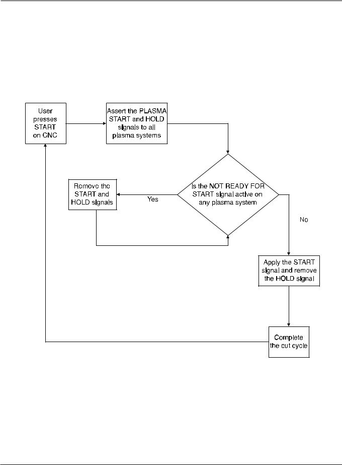
CNC operation with pump time-out
HPR260 Auto Gas Instruction Manual |
5-17 |
0
MAINTENANCE
Initial checks
Before trouble-shooting, do a visual check and verify that proper voltages are present at the power source, transformers and power distribution board.
WARNING
SHOCK HAZARD: Always use caution when servicing a power supply when plugged in and the covers are removed. Dangerous voltages exist within the power supply which could cause injury or death.
1.Disconnect line power by turning OFF the main disconnect switch.
2.Remove the power supply’s top panel and two side panels.
3.Inspect interior of power supply for discoloration on PC boards, or other apparent damage. If a component or module is obviously defective, replace it before doing any testing. Refer to the Parts List section to identify parts and part numbers.
4.If no damage is apparent, connect power to the power supply, and turn ON the main disconnect switch.
5.Measure the voltage between the W, V and U terminals of TB1 located on the right side of the power supply. See figure on next page. Also refer to the wiring diagram in Section 7, if required. The voltage between any 2 of the 3 terminals should be equal to the supply voltage. If there is a problem at this point, disconnect main power and check connections, power cable, and fuses at line disconnect switch. Repair or replace any defective component.
5-18 |
HPR260 Auto Gas Instruction Manual |
0
MAINTENANCE
Power measurement
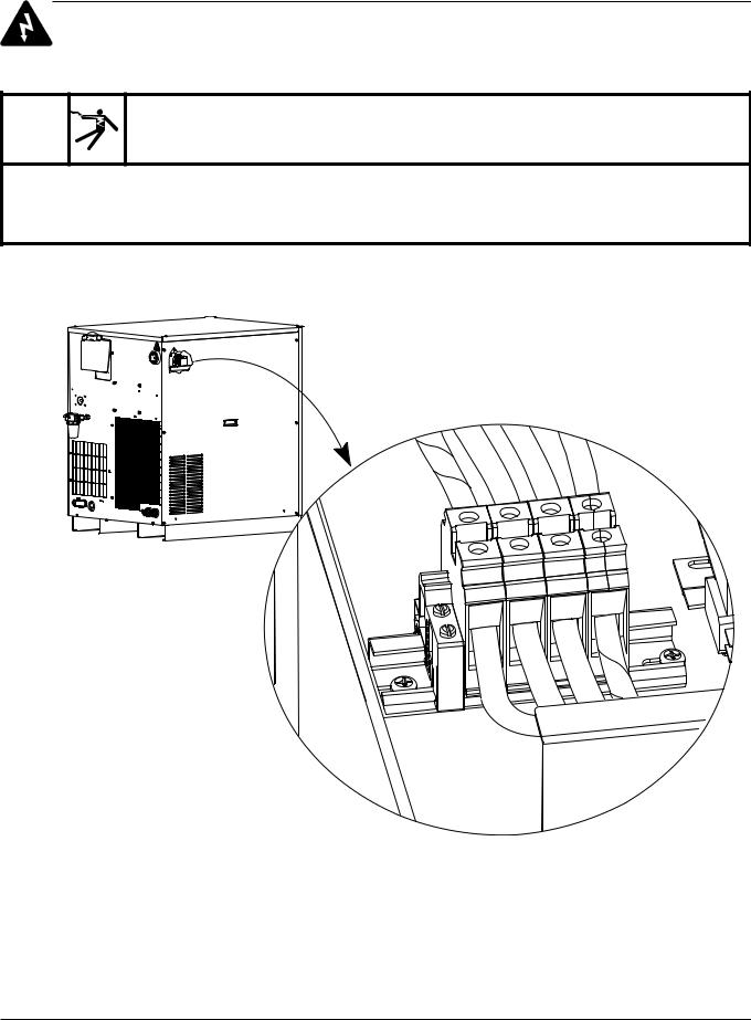
WARNING
There is line voltage at the contactor after the line disconnect switch is ON, even if the the circuit breaker on the power supply is OFF. Use extreme care when measuring primary power in these areas. Voltages present at the terminal block and contactors can cause injury or death.
PE |
W |
V |
U |
|
Note: Check lines in the following order: U to V
U to W V to W
Check each line to ground. If one line is 10% or higher than the two, put that leg on U.
HPR260 Auto Gas Instruction Manual |
5-19 |
0