

HPR 260 Manual Instrution
.pdfPARTS LIST
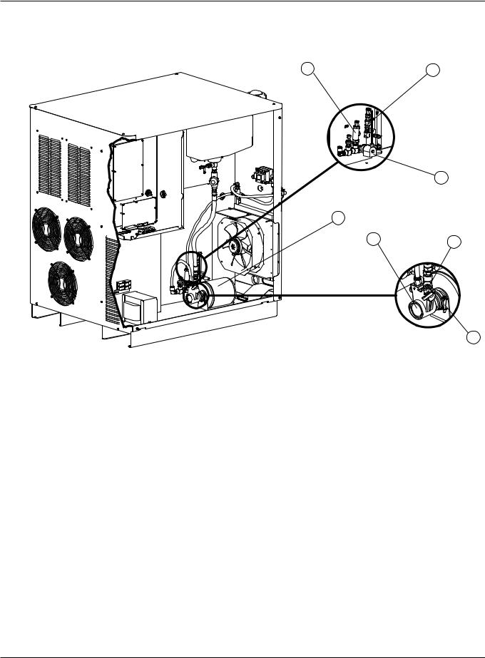
Power supply
4
3
5
2
 6
6
1 
7
|
Part |
|
|
|
Item |
Number |
Description |
Designator |
Qty. |
1 |
008551* |
Fuse: 7.5 amp, 600 volt |
F1, F2 |
2 |
|
008709** |
Fuse: 20 amp, 500 volt |
F1, F2 |
2 |
2 |
041909 |
Control PCB |
PCB3 |
1 |
3 |
041802 |
Power distribution PCB |
PCB2 |
1 |
4 |
027926 |
Filter assembly: 1/2" NPT low profile |
|
1 |
5 |
129793 |
Flow switch assembly |
FLS |
1 |
6 |
229066 |
Heat exchanger assembly |
|
1 |
|
127091 |
Fan: heat exchanger |
|
1 |
7 |
129786 |
Control transformer: 200/208 volt, 50-60 HZ |
|
1 |
|
129966 |
Control transformer: 240 volt, 60 HZ |
|
1 |
|
129787 |
Control transformer: 400 volt, 50-60 HZ |
|
1 |
|
229013 |
Control transformer: 440 volt, 50-60 HZ |
|
1 |
|
129967 |
Control transformer: 480 volt, 50-60 HZ |
|
1 |
|
129989 |
Control transformer: 600 volt, 50-60 HZ |
|
1 |
* 400, 440, 480 and 600 volt power supplies **200 and 240 volt power supplies
HPR260 Auto Gas Instruction Manual |
6-5 |
1
PARTS LIST
Power supply
1 |
2 |
3
4
5 6
7
|
Part |
|
|
|
Item |
Number |
Description |
Designator |
Qty. |
1 |
006132 |
Check valve: 1/4" NPT, 200 psi |
|
1 |
2 |
006075 |
Check valve: 1/4" FPT |
|
1 |
3 |
006046 |
Solenoid valve assembly: 3/8", 240 volt |
|
1 |
4 |
031113 |
Motor: 1/3 HP, 240 volt, 50-60 HZ |
|
1 |
5 |
031138 |
Pump: 80 gpm, 200 psi |
|
1 |
6 |
031115 |
Clamp |
|
1 |
7 |
006099 |
Bib drain valve:1/4 NPT |
|
1 |
6-6 |
HPR260 Auto Gas Instruction Manual |
0

PARTS LIST
Ignition console
1
2
3
4
|
Part |
|
|
|
Item |
Number |
Description |
Designator |
Qty. |
1 |
078172 |
Ignition Console |
|
|
2 |
129831 |
Coil assembly |
T2 |
1 |
3 |
041817 |
HFHV Ignition PCB |
|
1 |
4 |
129854 |
Transformer |
T1 |
1 |
HPR260 Auto Gas Instruction Manual |
6-7 |
0
PARTS LIST
Selection console – 1 of 2
1
2
3
4
 5
5
6
|
Part |
|
|
|
Item |
Number |
Description |
Designator |
Qty. |
1078185 Selection console
2 |
129633 |
Green power lamp |
|
1 |
3 |
041828 |
Control PCB |
|
1 |
4 |
005263 |
Pressure sensor |
PT1-PT4 |
4 |
5 |
006109 |
Solenoid valve |
SV1-SV14 |
14 |
|
006112 |
Replacement solenoid coil |
|
|
6 |
041897 |
Power distribution PCB |
|
1 |
6-8 HPR260 Auto Gas Instruction Manual
0

PARTS LIST
Selection console – 2 of 2
1
2 
|
Part |
|
|
|
Item |
Number |
Description |
Designator |
Qty. |
1 |
041822 |
Valve driver PCB |
PCB |
1 |
2 |
129999 |
Motor valve assembly |
|
2 |
Metering console
4 5
1
23
 6
6
8 
|
|
|
7 |
|
|
Part |
|
|
|
Item |
Number |
Description |
Designator |
Qty. |
1 |
078184 |
Metering console |
|
1 |
2 |
129633 |
Green power lamp |
|
1 |
3 |
041897 |
Power distribution PCB |
|
1 |
4 |
041828 |
Control PCB |
|
1 |
5 |
006077 |
Check valves |
|
2 |
6 |
006109 |
Solenoid valve |
|
1 |
|
006112 |
Replacement solenoid coil |
|
|
7 |
005263 |
Pressure sensor (1 not shown) |
|
4 |
8 |
006128 |
Proportional valve |
|
4 |
|
|
|
||
HPR260 Auto Gas Instruction Manual |
|
6-9 |
||
0

PARTS LIST
HyPerformance torch
Torch assembly
1
2 |
3 |
4 |
5 |
6 |
|
Part |
|
Item |
Number |
Description |
1 |
128818 |
HPR machine torch assembly |
2 |
220162 |
Quick-disconnect torch |
3 |
220340 |
Water tube with o-ring |
4 |
220163 |
Quick-disconnect receptacle |
5 |
024751 |
Insulating sleeve |
6 |
220232 |
Torch mounting sleeve assembly |
|
128879 |
Torch kit: bullet plugs, o-rings, water tube and seal |
|
128880 |
Quick disconnect kit: o-ring and connector |
Torch leads
Part |
|
Number |
Description |
128986 |
2 m (6 ft) |
128935 |
3 m (10 ft) |
128934 |
4.5 m (15 ft) |
128784 |
7.5 m (25 ft) |
128987 |
10 m (35 ft) |
128785 |
15 m (50 ft) |
128988 |
20 m (65 ft) |
|
|
6-10 |
HPR260 Auto Gas Instruction Manual |
0

|
|
PARTS LIST |
Consumable parts kit – 128878 |
|
|
Part |
|
|
Number |
Description |
Qty. |
001579 |
Box: gray plastic |
1 |
004630 |
Electrode gauge assembly |
1 |
026009 |
O-ring: .208" X .070" |
5 |
027012 |
Lubricant: silicone 2-oz tube |
1 |
044028 |
O-ring: 1.364" X .070" |
2 |
104119 |
Tool: consumable removal / replacement |
1 |
220173 |
Shield retaining cap with IHS tab |
1 |
220176 |
Nozzle retaining cap |
2 |
220179 |
Swirl ring: mild steel |
1 |
220180 |
Swirl ring: 30 amp mild steel |
1 |
220181 |
Electrode:130 amp mild steel |
3 |
220182 |
Nozzle: 130 amp mild steel |
3 |
220183 |
Shield: 130 amp mild steel |
2 |
220187 |
Electrode: 80 amp mild steel |
3 |
220188 |
Nozzle: 80 amp mild steel |
3 |
220189 |
Shield: 80 amp mild steel |
2 |
220192 |
Electrode: 30 amp mild steel |
2 |
220193 |
Nozzle: 30 amp mild steel |
2 |
220194 |
Shield: 30 amp mild steel |
1 |
220197 |
Nozzle: 130 amp stainless steel |
2 |
220198 |
Shield: 130 amp stainless steel |
1 |
220201 |
Nozzle: 45 amp stainless steel |
2 |
220202 |
Shield: 45 amp stainless steel |
1 |
220304 |
Nozzle retaining cap |
1 |
220307 |
Electrode: 130 amp stainless steel |
2 |
220308 |
Electrode: 45 amp stainless steel |
2 |
220313 |
Nozzle retaining cap: 30 amp |
1 |
220337 |
Nozzle: 80 amp stainless steel |
2 |
220338 |
Shield: 80 amp stainless steel |
1 |
220339 |
Electrode: 80 amp stainless steel |
2 |
220340 |
Water tube with o-ring |
1 |
HPR260 Auto Gas Instruction Manual |
6-11 |
0

PARTS LIST
Mirror image cutting consumables
Mild steel
Shield cap |
Shield |
Retaining cap |
Nozzle |
Swirl ring |
Electrode |
30A
220194 |
220314 |
220193 |
220306 |
220192 |
80A
220173 |
220189 |
220304 |
220188 |
220305 |
220187 |
130A
220183 |
220304 |
220182 |
220305 |
220181 |
200A
220356 |
220351 |
220354 |
220350 |
220352 |
260A 220398
220440 |
220441 |
220439 |
220442 |
220435 |
6-12 |
HPR260 Auto Gas Instruction Manual |
0

PARTS LIST
Recommended spare parts
Power supply
Part |
|
|
|
Number |
Description |
Designator |
Qty. |
129633 |
Green power lamp assembly |
|
1 |
027634 |
Filter housing |
|
1 |
027664 |
Filter element |
|
1 |
129792 |
Chopper assembly |
CH1 |
1 |
127039 |
6" fan :230 CFM, 115 VAC 50-60 HZ |
|
1 |
027079 |
10" fan :450-550 CFM, 120 VAC 50-60 HZ |
|
1 |
003149 |
Relay: pilot arc, 120 VAC |
CR1 |
1 |
041837 |
PCB: I/O |
|
1 |
003139 |
Contactor |
CON1 |
1 |
109004 |
Current sensor: hall 100 amp, 4 volt |
|
1 |
129791 |
Start circuit assembly |
PCB1 |
1 |
108263 |
Fuse: 150 amp, 250 volt |
F3 |
1 |
008551* |
Fuse: 7.5 amp, 600 volt |
F1, F2 |
2 |
041909 |
Control PCB |
PCB3 |
1 |
041802 |
Power distribution PCB |
PCB2 |
1 |
129793 |
Flow switch assembly |
FLS |
1 |
027185 |
Heat exchanger fan: 4" |
|
1 |
006075 |
Check valve: 1/4" FPT |
|
1 |
129995 |
Solenoid valve assembly |
CLT SOL |
1 |
129994 |
Pump assembly: 70 gpm, 200 psi |
|
1 |
031113 |
Motor: 1/3 HP, 240 volt, 50-60 HZ |
|
1 |
* 400, 480 and 600 volt power supplies |
|
|
|
Ignition console
Part |
|
|
|
Number |
Description |
Designator |
Qty. |
041817 |
HFHV Ignition PCB |
|
1 |
129854 |
Transformer |
T1 |
1 |
Selection and Metering consoles
Part |
|
|
|
Number |
Description |
Designator |
Qty. |
041828 |
Control PCB |
|
1 |
041897 |
Power distribution PCB |
|
1 |
041822 |
Valve driver PCB |
|
1 |
006109 |
Solenoid valve |
|
2 |
005263 |
Pressure sensor |
|
1 |
HPR260 Auto Gas Instruction Manual |
6-13 |
0

Section 7
WIRING DIAGRAMS
Introduction
This section contains the wiring diagrams for the system. When tracing a signal path or referencing with the Parts List or Troubleshooting sections, please be aware of the following format to assist you in understanding the wiring diagrams' organization:
•Sheet numbers are located in the lower right-hand corner.
•Page-to-page referencing is done in the following manner:
CSHEET 4-D3
Source Connection |
Source Reference Block |
Destination Sheet # |
Destination |
|
|
|
Coordinates |
SHEET C 4-D3
Source Sheet # |
Source Coordinates |
Source Reference Block |
Destination |
|
|
|
Coordinates |
Destination and Source Coordinates refer to letters A-D on the Y-axis of each sheet and numbers 1-4 on the X-axis of each sheet. Lining up the coordinates will bring you to the source or destination blocks (similar to a road map).
Wiring diagram symbols
Wiring diagram symbols and their identification precede the system wiring diagrams in this section.
HPR260 Auto Gas Instruction Manual |
7-1 |
0