

HPR 260 Manual Instrution
.pdf0 |
2-7 |
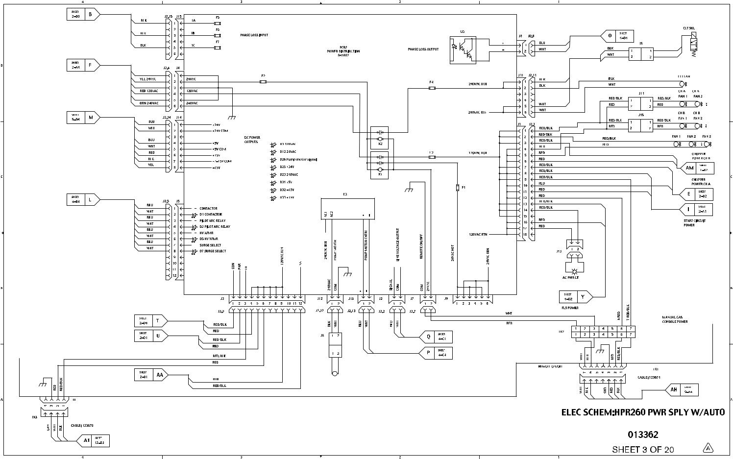
Manual Instruction Gas Auto HPR260
Battery
Cap, polarized
Cap, non-polarized
Cap, feed-thru
Circuit breaker
Coax shield
Current Sensor
Current sensor
DC supply
Diode
Door interlock
Fan
Feedthru LC
Filter, AC
Fuse
Ground Clamp
Ground, Chassis
Ground, Earth
IGBT
Inductor
LED
Light
MOV
Pin
Plug
PNP Transistor
Potentiometer
Push Button,
Normally Closed
Push Button,
Normally Open
Receptacle
Relay, Coil
Relay, Normally Closed
Relay, Normally Open
Relay, Solid State, AC
Relay, Solid State, DC
Relay, Solid State, Dry
Resistor
SCR
Shield
Shunt
Spark Gap
Switch, Flow
DIAGRAMS WIRING

Manual Instruction Gas Auto HPR260
0 |
3-7 |
Switch, Level,
Normally Closed
Switch, Pressure,
Normally Closed
Switch, Pressure,
Normally Open
Switch, 1 Pole, 1 Throw
Switch, 1 Pole, 2 Throw
Switch, 1 Pole, 1 Throw,
Center Off
Switch, Temperature,
Normally Closed
Switch, Temperature,
Normally Open
Terminal Block
Time Delay Closed,
NC/Off
Time Delay Open,
NO/Off
Time Delay Open,
NC/On
Time Delay Closed,
NO/Off
Transformer
Transformer, Air Core
Transformer Coil
Triac
VAC Source
Valve, Solenoid
Voltage Source
Zener Diode
Torch Symbols
Electrode
Nozzle
Shield
Torch
Torch, HyDefinition™
DIAGRAMS WIRING

Discrete output functionality
HPR260 Auto Gas Instruction Manual |
7-5 |
0

7-7
0

7-9 |
0 |
7-11
0

7-13 |
0 |

7-15 |
0 |

7-17
0

7-19
0