

HPR 260 Manual Instrution
.pdfOPERATION
Aluminum |
|
Flow Rates – lpm/scfh |
|||
H35 Plasma / N2 Shield |
|
|
H35 |
N2 |
|
Preflow |
|
0 |
/ 0 |
127 / 270 |
|
260 A Cutting |
|
|
|
|
|
Cutflow |
|
33 |
/ 70 |
118 / 250 |
|
220398 220407 220344 220406 220405 220307
Metric
Select |
Set |
Set |
Material |
Arc |
Torch-to-Work |
Cutting |
Initial Pierce |
Pierce Delay |
|||||
Gases |
Preflow |
Cutflow |
Thickness |
Voltage |
Distance |
Speed |
Height |
Time |
|||||
Plasma |
Shield |
Plasma |
Shield |
Plasma |
Shield |
mm |
Volts |
mm |
mm/m |
mm |
factor % |
seconds |
|
|
|
|
|
|
|
6 |
170 |
11.0 |
7200 |
11.0 |
100 |
0.2 |
|
|
|
|
|
|
|
|
|
|
|
|
|||
|
|
|
|
|
|
10 |
170 |
10.0 |
6120 |
10.0 |
100 |
0.4 |
|
|
|
|
|
|
|
|
|
|
|
|
|||
|
|
|
|
|
|
12 |
162 |
|
5160 |
|
|
0.5 |
|
|
|
|
|
|
|
|
|
|
|
|
|||
|
|
|
|
|
|
15 |
163 |
|
3720 |
8.5 |
110 |
0.6 |
|
|
|
|
|
|
|
|
|
|
|
||||
H35 |
N2 |
12 |
60 |
76 |
69 |
20 |
166 |
|
2230 |
|
|
0.6 |
|
|
|
|
|
||||||||||
25 |
174 |
7.6 |
1930 |
11.0 |
150 |
0.8 |
|||||||
|
|
|
|
|
|
||||||||
|
|
|
|
|
|
|
|
|
|||||
|
|
|
|
|
|
32 |
175 |
1510 |
|
|
|
||
|
|
|
|
|
|
|
|
|
|
||||
|
|
|
|
|
|
38 |
176 |
|
1150 |
|
N/A |
|
|
|
|
|
|
|
|
44 |
183 |
|
670 |
|
|
||
|
|
|
|
|
|
|
|
|
|
||||
|
|
|
|
|
|
50 |
190 |
|
390 |
|
|
|
|
English
Select |
Set |
Set |
Material |
Arc |
Torch-to-Work |
Cutting |
Initial Pierce |
Pierce Delay |
|||||
Gases |
Preflow |
Cutflow |
Thickness |
Voltage |
Distance |
Speed |
Height |
Time |
|||||
Plasma |
Shield |
Plasma |
Shield |
Plasma |
Shield |
in |
Volts |
in |
ipm |
in |
factor % |
seconds |
|
|
|
|
|
|
|
1/4 |
170 |
0.450 |
280 |
0.450 |
100 |
0.2 |
|
|
|
|
|
|
|
|
|
|
|
|
|||
|
|
|
|
|
|
3/8 |
170 |
0.400 |
250 |
0.400 |
100 |
0.4 |
|
|
|
|
|
|
|
|
|
|
|
|
|||
|
|
|
|
|
|
1/2 |
162 |
|
190 |
|
|
0.5 |
|
|
|
|
|
|
|
|
|
|
|
|
|||
|
|
|
|
|
|
5/8 |
163 |
|
130 |
0.330 |
110 |
0.6 |
|
|
|
|
|
|
|
|
|
|
|
||||
H35 |
N2 |
12 |
60 |
76 |
69 |
3/4 |
166 |
|
90 |
|
|
0.6 |
|
|
|
|
|
||||||||||
1 |
174 |
0.300 |
75 |
0.450 |
150 |
0.8 |
|||||||
|
|
|
|
|
|
||||||||
|
|
|
|
|
|
|
|
|
|||||
|
|
|
|
|
|
1-1/4 |
175 |
60 |
|
|
|
||
|
|
|
|
|
|
|
|
|
|
||||
|
|
|
|
|
|
1-1/2 |
176 |
|
45 |
|
N/A |
|
|
|
|
|
|
|
|
1-3/4 |
183 |
|
25 |
|
|
||
|
|
|
|
|
|
|
|
|
|
||||
|
|
|
|
|
|
2 |
190 |
|
14 |
|
|
|
|
Marking
|
|
|
|
|
|
|
|
|
Amperage |
Torch-to-Work |
Marking |
Arc Voltage |
|
||
Select |
|
|
Set |
|
Set |
Distance |
Speed |
|
|||||||
|
|
|
|
|
|
||||||||||
|
|
|
|
|
|
|
|
|
|
||||||
Gases |
|
Preflow |
Cutflow |
Amps |
mm |
in |
mm/min |
ipm |
Volts |
|
|||||
N2 |
|
N2 |
10 |
|
10 |
10 |
|
10 |
18 |
2.5 |
0.100 |
6350 |
250 |
120 |
|
|
|
|
|
|
|
|
|
|
|
|
|
|
|
|
|
4-38 |
|
|
|
|
|
|
|
|
|
|
|
HPR260 Auto Gas Instruction Manual |
|||
1

OPERATION
Aluminum |
|
Flow Rates – lpm/scfh |
|
||
N2 Plasma / Air Shield |
|
|
N2 |
Air |
|
Preflow |
|
125 / 265 |
0 |
/ 0 |
|
260 A Cutting |
|
|
|
|
|
Cutflow |
|
50 / 105 |
113 |
/ 240 |
|
220398 220407 220344 220406 220405 220307
Metric
Select |
Set |
Set |
Material |
Arc |
Torch-to-Work |
Cutting |
Initial Pierce |
Pierce Delay |
|||||
Gases |
Preflow |
Cutflow |
Thickness |
Voltage |
Distance |
Speed |
Height |
Time |
|||||
Plasma |
Shield |
Plasma |
Shield |
Plasma |
Shield |
mm |
Volts |
mm |
mm/m |
mm |
factor % |
seconds |
|
|
|
|
|
|
|
6 |
172 |
6.40 |
7900 |
9.0 |
140 |
0.2 |
|
|
|
|
|
|
|
10 |
171 |
4930 |
0.4 |
||||
|
|
|
|
|
|
|
|
|
|||||
|
|
|
|
|
|
12 |
164 |
|
4290 |
|
|
0.5 |
|
|
|
|
|
|
|
15 |
165 |
|
3330 |
8.0 |
200 |
0.6 |
|
N2 |
Air |
12 |
60 |
74 |
69 |
20 |
171 |
|
1940 |
|
|
||
|
|
|
|
||||||||||
25 |
177 |
4.00 |
1440 |
11.0 |
260 |
0.8 |
|||||||
|
|
|
|
|
|
||||||||
|
|
|
|
|
|
32 |
191 |
940 |
|
|
|
||
|
|
|
|
|
|
|
|
|
|
||||
|
|
|
|
|
|
38 |
195 |
|
520 |
|
N/A |
|
|
|
|
|
|
|
|
44 |
202 |
|
320 |
|
|
||
|
|
|
|
|
|
|
|
|
|
||||
|
|
|
|
|
|
50 |
205 |
|
215 |
|
|
|
|
English
Select |
Set |
Set |
Material |
Arc |
Torch-to-Work |
Cutting |
Initial Pierce |
Pierce Delay |
|||||
Gases |
Preflow |
Cutflow |
Thickness |
Voltage |
Distance |
Speed |
Height |
Time |
|||||
Plasma |
Shield |
Plasma |
Shield |
Plasma |
Shield |
in |
Volts |
in |
ipm |
in |
factor % |
seconds |
|
|
|
|
|
|
|
1/4 |
172 |
0.250 |
300 |
0.350 |
140 |
0.2 |
|
|
|
|
|
|
|
3/8 |
171 |
200 |
0.4 |
||||
|
|
|
|
|
|
|
|
|
|||||
|
|
|
|
|
|
1/2 |
164 |
|
160 |
|
|
0.5 |
|
|
|
|
|
|
|
5/8 |
165 |
|
120 |
0.320 |
200 |
0.6 |
|
N2 |
Air |
12 |
60 |
74 |
69 |
3/4 |
171 |
|
80 |
|
|
||
|
|
|
|
||||||||||
1 |
177 |
0.160 |
55 |
0.420 |
260 |
0.8 |
|||||||
|
|
|
|
|
|
||||||||
|
|
|
|
|
|
1-1/4 |
191 |
40 |
|
|
|
||
|
|
|
|
|
|
|
|
|
|
||||
|
|
|
|
|
|
1-1/2 |
195 |
|
20 |
|
N/A |
|
|
|
|
|
|
|
|
1-3/4 |
202 |
|
12 |
|
|
||
|
|
|
|
|
|
|
|
|
|
||||
|
|
|
|
|
|
2 |
205 |
|
8 |
|
|
|
|
Marking
|
|
|
|
|
|
|
|
|
Amperage |
Torch-to-Work |
Marking |
Arc Voltage |
||
|
Select |
|
Set |
|
Set |
Distance |
Speed |
|||||||
|
|
|
|
|||||||||||
|
Gases |
Preflow |
Cutflow |
Amps |
mm |
in |
mm/min |
ipm |
Volts |
|||||
N2 |
|
N2 |
10 |
|
10 |
10 |
|
10 |
18 |
2.5 |
0.100 |
6350 |
250 |
120 |
|
|
|
|
|
|
|
|
|
|
|
|
|
|
|
HPR260 Auto Gas Instruction Manual |
4-39 |
1
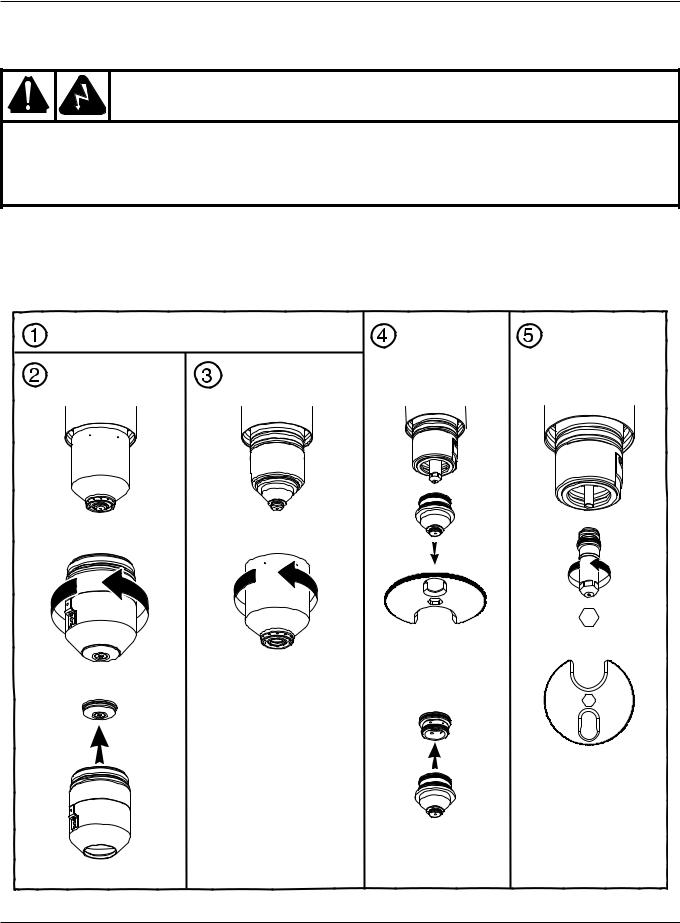
OPERATION
Changing consumable parts
WARNING
The system is designed to go into an idle mode if the retaining cap is removed. However, DO NOT CHANGE CONSUMABLE PARTS WHILE IN THE IDLE MODE. Always disconnect power to the power supply before inspecting or changing torch consumable parts. Use gloves when removing consumables. The torch might be hot.
Remove consumables
Check the consumable parts daily for wear before cutting. Before removing consumables, bring the torch to the edge of the cutting table, with the torch lifter raised to its highest point to prevent the consumables from dropping into the water of the water table.
Turn OFF all power to the system. |
Remove nozzle |
Remove |
|
|
|
and swirl ring |
electrode |
Remove retaining cap |
Remove inner |
|
|
and shield |
retaining cap |
|
|
Tool part number 104119
4-40 |
HPR260 Auto Gas Instruction Manual |
0
OPERATION
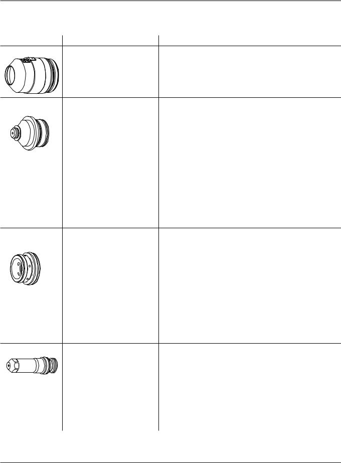
Inspect consumables |
|
||
Part |
|
Check for |
Action |
Cap |
|
Erosion, missing material |
Replace cap |
|
|
||
|
|
Cracks |
Replace cap |
|
|
Burned |
Replace cap |
Nozzle |
|
|
|
|
Erosion or missing material |
Replace nozzle* |
|
|
Blocked gas holes |
Replace nozzle* |
|
Center hole |
1. |
Must be round |
Replace nozzle if hole is no longer round* |
|
2. |
Signs of arcing |
Replace nozzle* |
O-rings |
1. Damage |
Replace nozzle* |
|
|
2. |
Lubricant |
Apply a thin film of silicone lubricant if dry |
Swirl ring |
|
|
|
|
Damage |
Replace swirl ring |
|
|
Dirt or debris |
Clean and check for damage; replace if damaged |
|
Gas holes |
Blocked holes |
Replace swirl ring |
|
O-rings |
1. |
Damage |
Replace swirl ring |
|
2. |
Lubricant |
Apply a thin film of silicone lubricant if dry |
Electrode |
|
|
|
Center surface |
Wear |
See Inspect electrode pit depth later in |
|
this section |
|||
O-rings |
1. |
Damage |
Replace electrode* |
|
2. |
Lubricant |
Apply a thin film of silicone lubricant if dry |
*Note: Always replace the nozzle and electrode as a set.
HPR260 Auto Gas Instruction Manual |
4-41 |
0
OPERATION
Inspect torch
Bullet connectors
Water tube
Shield gas
Plasma vent 
Pilot arc
Current ring
Plasma gas |
Coolant in |
Coolant return |
Inspect |
|
Check for |
Action |
|
|
|
|
All surfaces |
Dirt or debris |
Clean surfaces |
|
|
Erosion, missing material |
Replace torch |
|
|
Cracks |
Replace torch |
|
|
Internal burn or arcing marks |
Replace torch |
|
|
|
|
|
Current ring |
1. |
Dirt or debris |
Clean |
|
2. |
Pitted or missing material |
Replace torch |
|
|
|
|
Threads |
Wear or damage |
Replace torch |
|
|
|
|
|
Bullet connectors |
Damage |
Replace torch |
|
O-rings |
1. |
Damage |
Replace o-ring |
|
2. |
Lubricant |
Apply a thin film of silicone lubricant if dry |
|
|
|
|
External o-rings |
1. |
Damage |
Replace o-ring |
|
2. |
Lubricant |
Apply a thin film of silicone lubricant if dry |
|
|
|
|
Water tube* |
1. |
Tightness |
Tighten or replace tube* |
|
2. |
Pitted or missing material |
Replace tube* |
|
|
|
|
*Note: See Replace torch water tube later in this section.
4-42 |
HPR260 Auto Gas Instruction Manual |
0

OPERATION
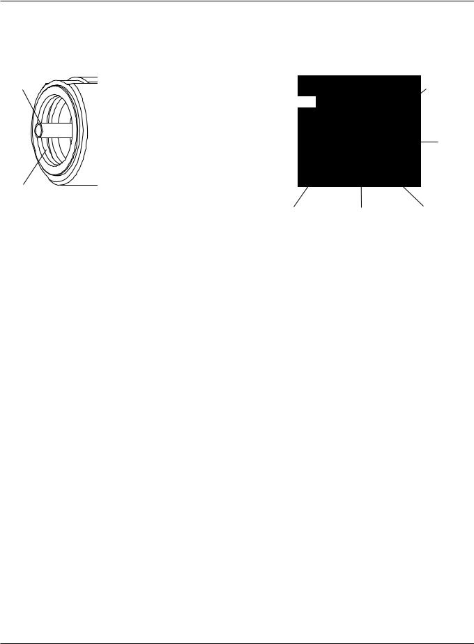
Inspect electrode pit depth
|
|
0 |
|
90 |
10 |
|
|
0 |
|
1 |
4 |
80 |
2 |
3 |
|
20 |
|
|
|
|
70 |
|
30 |
|
60 |
40 |
|
|
50 |
Electrode pit depth gauge (004630)
Part |
Check for |
Action |
Electrode
Center surface |
Wear |
Replace electrode if pit is deeper than 1 mm (0.040 in.)* |
*Note: Always replace the nozzle and electrode as a set.
HPR260 Auto Gas Instruction Manual |
4-43 |
0
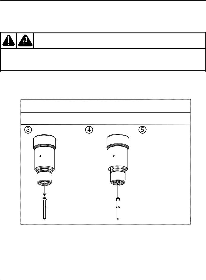
OPERATION
Replace torch water tube
WARNING
The system is designed to go into an idle mode if the retaining cap is removed. However, DO NOT REMOVE CONSUMABLE PARTS WHILE IN THE IDLE MODE. Always disconnect power to the power supply before removing torch consumable parts.
Note: The water tube may seem loose when correctly inserted, but any side-to-side looseness will disappear after the electrode is installed.
 Turn OFF all power to the system.
 Remove consumables from torch. See Remove consumables in this section.
Remove water tube |
Install new water tube |
Replace consumables. |
|
|
See Install consumables |
|
|
in this section. |
4-44 |
HPR260 Auto Gas Instruction Manual |
0

OPERATION
Common cutting faults
•Torch pilot arc will initiate, but will not transfer. Causes can be:
1.Work cable connection on the cutting table is not making good contact.
2.Malfunction in the system. See Section 5..
3.Torch-to-work distance is too high.
•The workpiece is not totally penetrated, and there is excessive sparking on top of the workpiece. Causes can be:
1.Current is set too low (check Cut chart information).
2.Cut speed is too high (check Cut chart information).
3.Torch parts are worn (see Changing consumable parts).
4.Metal being cut is too thick.
•Dross forms on the bottom of the cut. Causes can be:
1.Cutting speed is not correct (check Cut chart information).
2.Arc current is set too low (check Cut chart information).
3.Torch parts are worn (see Changing consumable parts).
•Cut angle is not square. Causes can be:
1.Wrong direction of machine travel.
High-quality side is on the right with respect to the forward motion of the torch.
2.Torch-to-work distance is not correct (check Cut chart information).
3.Cutting speed is not correct (check Cut chart information).
4.Arc current is not correct (check Cut chart information).
5.Damaged consumable parts (see Changing consumable parts ).
•Short consumable life. Causes can be:
1.Arc current, arc voltage, travel speed, motion delay, gas flow rates, or initial torch height not set as specified in the Cut charts.
2.Attempting to cut highly magnetic metal plate, such as armor plate with a high nickel content, will shorten consumable life. Long consumable life is difficult to achieve when cutting plate that is magnetized or becomes magnetized easily.
3.Beginning or ending the cut off the plate surface. To achieve consumable long life, all cuts must begin and end on the plate surface.
HPR260 Auto Gas Instruction Manual |
4-45 |
0

OPERATION
How to optimize cut quality
The following tips and procedures will help produce square, straight, smooth and dross-free cuts.
Tips for table and torch
•Use a square to align the torch at right angles to the workpiece.
•The torch may travel more smoothly if you clean, check and “tune” the rails and drive system on the cutting table. Unsteady machine motion can cause a regular, wavy pattern on the cut surface.
•The torch must not touch the workpiece during cutting. Contact can damage the shield and nozzle, and affect the cut surface.
Plasma set-up tips
Follow carefully each step in the Daily start-up procedure described earlier in this section.
Purge the gas lines before cutting.
Maximize the life of consumable parts
Hypertherm’s LongLife® process automatically “ramps up” the gas and current flows at the start and ramps them down at the end of each cut, to minimize erosion of the electrode’s center surface. The LongLife process also requires that cuts start and stop on the workpiece.
•The torch should never fire into the air.
–Starting the cut at the edge of the workpiece is acceptable, as long as the arc is not fired in the air.
–To start with a pierce, use a pierce height that is 1.5 to 2 times the torch-to-work distance. See Cut charts.
•Each cut should end with the arc still attached to the workpiece, to avoid arc blow-outs (ramp-down errors).
–When cutting drop parts (small parts that drop down after being cut from the workpiece), check that the arc stays attached to the edge of the workpiece, for proper ramp-down.
•If arc blow-outs occur, try one or more of the following:
–Reduce the cutting speed during the final part of the cut.
–Stop the arc before the part is completely cut, to allow completion of the cut during the ramp-down.
–Program the path of the torch into the scrap area for ramp-down.
Note: Use a “chain cut” if possible, so the path of the torch can lead directly from one cut part into the next, without stopping and starting the arc. However, do not allow the path to lead off the workpiece and back on, and remember that a chain cut of long duration will cause electrode wear.
Note: It may be difficult to achieve the full benefits of the LongLife process in some conditions.
4-46 |
HPR260 Auto Gas Instruction Manual |
0
OPERATION
Additional factors of cut quality
Cut angle
A cut part whose 4 sides average less than 4° of cut angle is considered acceptable.
Note: The squarest cut angle will be on the right side with respect to the forward motion of the torch.
Note: To determine whether a cut-angle problem is being caused by the plasma system or the drive system, make a test cut and measure the angle of each side. Next, rotate the torch 90° in its holder and repeat the process. If the angles are the same in both tests, the problem is in the drive system.
If a cut-angle problem persists after “mechanical causes” have been eliminated (see Tips for table and torch, previous page), check the torch-to-work distance, especially if cut angles are all positive or all negative.
•A positive cut angle results when more material is removed from the top of the cut than from the bottom.
•A negative cut angle results when more material is removed from the bottom of the cut.
Problem |
Cause |
Negative cut angle |
The torch is too low. |
Square cut |
|
Positive cut angle |
The torch is too high. |
\ |
|
Dross
Solution
Increase arc voltage to raise the torch.
Decrease arc voltage to lower the torch.
Low-speed dross forms when the torch’s cutting speed is too slow and the arc shoots ahead. It forms as a heavy, bubbly deposit at the bottom of the cut and can be removed easily. Increase the speed to reduce the dross.
High-speed dross forms when the cutting speed is too fast and the arc lags behind. It forms as a thin, linear bead of solid metal attached very close to the cut. It is welded to the bottom of the cut and is difficult to remove. To reduce high-speed dross:
•Decrease the cutting speed.
•Decrease arc voltage, to decrease the torch-to-work distance.
•Increase O2 in the shield gas to increase the range of dross-free cutting speeds. (Only HyDefinition and HT4400 systems can accommodate mixed-gas shield gases.)
Notes: Dross is more likely to form on warm or hot metal than on cool metal. For example, the first cut in a series of cuts will likely produce the least dross. As the workpiece heats up, more dross may form on subsequent cuts.
Dross is more likely to form on mild steel than on stainless steel or aluminum.
Worn or damaged consumables may produce intermittent dross.
HPR260 Auto Gas Instruction Manual |
4-47 |
0