

HPR 260 Manual Instrution
.pdfOPERATION
Straightness of the cut surface
A typical plasma cut surface is slightly concave.
The cut surface may become more concave, or convex. Correct torch height is required to keep the cut surface acceptably close to straight.
A strongly concave cut surface occurs when the torch-to-work distance is too low. Increase the arc voltage to increase the torch-to-work distance and straighten the cut surface.
A convex cut surface occurs when the torch-to-work distance is too great or the cutting current is too high. First, reduce the arc voltage, then reduce the cutting current. If there is overlap between different cutting currents for that thickness, try the consumables designed for the lower current.
Additional improvements
Some of these improvements involve trade-offs, as described.
Smoothness of cut surface (surface finish)
•(HyDefinition and HT4400 only) On mild steel, a higher concentration of N2 in the O2-N2 shield mixture may produce a smoother cut surface.
Trade-off: This may produce more dross.
•(HyDefinition and HT4400 only) On mild steel, a higher concentration of O2 in the O2-N2 shield mixture may increase the cutting speed and produce less dross.
Trade-off: This may produce a rougher cut surface.
Piercing
The pierce delay must be sufficiently long that the arc can pierce the material before the torch moves, but not so long that the arc “wanders” while trying to find the edge of a large hole.
When piercing maximum thicknesses, the ring of dross that forms during the pierce may become high enough to contact the torch when the torch begins to move after the pierce is complete.
•A “flying pierce,” which makes the pierce while the torch is moving, may eliminate the torch vibration that follows contact between the torch and the ring of dross.
•In some Hypertherm systems, the shield gas pressure automatically increases during pierce delay.
•If the above steps do not solve the problem, increasing the setting of the shield gas pressure may help blow the molten metal away during piercing.
Trade-off: This may reduce starting reliability.
How to increase cutting speed
•Decrease the torch-to-work distance.
Trade-off: This will increase the negative cut angle
Note: The torch must not touch the workpiece while piercing or cutting.
4-48 |
HPR260 Auto Gas Instruction Manual |
0

Section 5
MAINTENANCE
In this section:
Introduction ............................................................................................................................................................... |
5-2 |
Routine maintenance................................................................................................................................................ |
5-2 |
System description ................................................................................................................................................... |
5-3 |
Control and signal cables................................................................................................................................. |
5-3 |
Sequence of operation.............................................................................................................................................. |
5-4 |
PCB block plasma and CNC operation with pump time-out diagram ....................................................................... |
5-5 |
Error codes ............................................................................................................................................................... |
5-6 |
Error code troubleshooting – 1 of 8.................................................................................................................. |
5-7 |
Error code troubleshooting – 2 of 8.................................................................................................................. |
5-8 |
Error code troubleshooting – 3 of 8.................................................................................................................. |
5-9 |
Error code troubleshooting – 4 of 8................................................................................................................ |
5-10 |
Error code troubleshooting – 5 of 8 ................................................................................................................ |
5-11 |
Error code troubleshooting – 6 of 8................................................................................................................ |
5-12 |
Error code troubleshooting – 7 of 8................................................................................................................ |
5-13 |
Error code troubleshooting – 8 of 8................................................................................................................ |
5-14 |
Power supply states................................................................................................................................................ |
5-15 |
Plasma system operation with pump time-out ........................................................................................................ |
5-16 |
CNC operation with pump time-out......................................................................................................................... |
5-17 |
Initial checks ........................................................................................................................................................... |
5-18 |
Power measurement............................................................................................................................................... |
5-19 |
Power supply coolant system servicing .................................................................................................................. |
5-20 |
Draining the coolant system........................................................................................................................... |
5-20 |
Coolant system filter ............................................................................................................................................... |
5-21 |
Filter replacement .......................................................................................................................................... |
5-21 |
Coolant flow test procedure .................................................................................................................................... |
5-22 |
Testing the flow switch ................................................................................................................................... |
5-23 |
Gas leak test procedure.......................................................................................................................................... |
5-24 |
Power supply control board PCB3.......................................................................................................................... |
5-25 |
Power supply power distribution board PCB2 ........................................................................................................ |
5-26 |
Start circuit PCB1 ................................................................................................................................................... |
5-27 |
Operation ....................................................................................................................................................... |
5-27 |
Start circuit functional schematic.................................................................................................................... |
5-27 |
Start circuit troubleshooting............................................................................................................................ |
5-27 |
Pilot arc current levels.................................................................................................................................... |
5-29 |
Selection console control board PCB2 ................................................................................................................... |
5-30 |
Selection console power distribution PCB1 ............................................................................................................ |
5-31 |
Selection console AC valve-driver PCB3................................................................................................................ |
5-32 |
Metering console control PCB ................................................................................................................................ |
5-33 |
Metering console power distribution PCB............................................................................................................... |
5-34 |
Chopper module test procedure ............................................................................................................................. |
5-35 |
Phase-loss detection test........................................................................................................................................ |
5-36 |
Torch lead test ........................................................................................................................................................ |
5-38 |
Preventive maintenance ......................................................................................................................................... |
5-39 |
|
|
HPR260 Auto Gas Instruction Manual |
5-1 |
0
MAINTENANCE
Introduction
Hypertherm assumes that the service personnel performing the troubleshooting testing are high-level electronic service technicians who have worked with high-voltage electro-mechanical systems. Knowledge of final isolation troubleshooting techniques is also assumed.
In addition to being technically qualified, maintenance personnel must perform all testing with safety in mind. Refer to the Safety section for operating precautions and warning formats.
WARNING
SHOCK HAZARD
Use extreme care when working near the chopper modules. The large blue capacitors store high voltage. Even if the power is off, dangerous voltages exist at the capacitor terminals, on the chopper and the heatsinks. Discharging any capacitor with a screwdriver or other implement may result in an explosion, property damage or personal injury. Wait at least 5 minutes after turning the power supply off before touching the chopper or the capacitors.
Routine maintenance
For a complete list of routine maintenance recommendations, see the Preventive Maintenance Schedule, located at the end of this section. Contact the Technical Services department listed at the front of this manual with any questions regarding the maintenance schedule or procedures.
5-2 |
HPR260 Auto Gas Instruction Manual |
0
MAINTENANCE
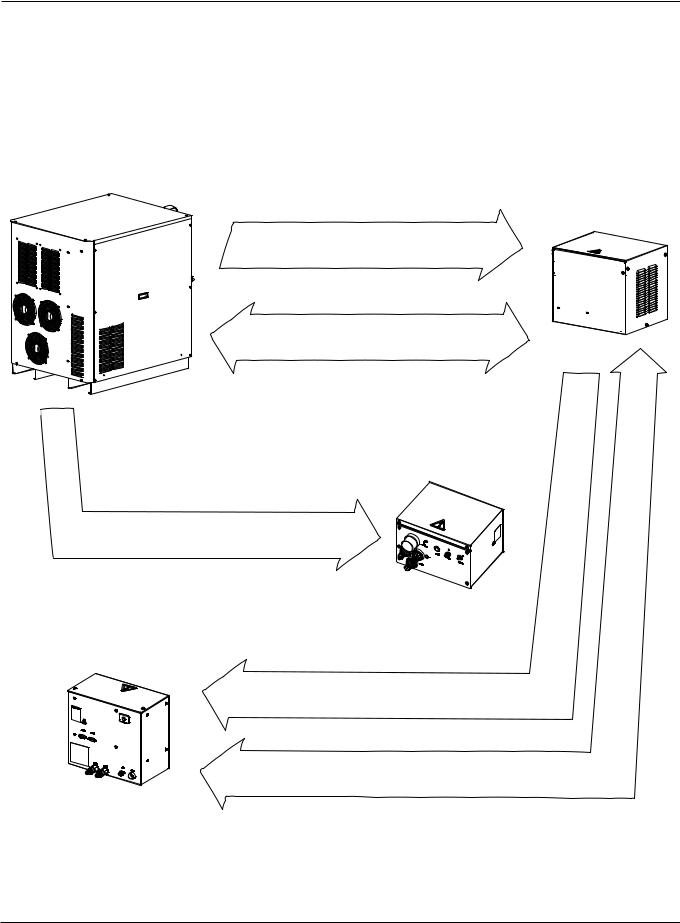
System description
Control and signal cables
Power cable: Provides 120 VAC to the selection console.
CAN Bus signal cable: Provides process and status signals between the power supply and the selection Console.
Power cable: Provides 120 VAC to the ignition console.
Power cable: Provides 120 VAC to the metering console.
CAN Bus signal cable: Provides process and status signals between the power supply and the metering console.
HPR260 Auto Gas Instruction Manual |
5-3 |
0

MAINTENANCE
Sequence of operation
1.Power-up – The system verifies that all of these signals are off at power-up Coolant flow off
Chopper current off Transfer off Phase-loss off
Chopper 1 over-temp off Magnetics over-temp off Coolant over-temp off Plasma start off
2.Purge – Air or N2 gas flows through torch for 20 seconds
Contactor closes and the chopper performs a chopper test and a current sensor test
Plasma start off
Contactor opens when the purge cycle ends
3. Idle
Gas pressure ok Coolant flow on Chopper current off Line voltage ok
4.Preflow – 2-second flow of gas
5.Pilot arc – Current flows between electrode and nozzle Chopper, main contactor and pilot arc relay are on High frequency present
Chopper current sensor = pilot arc current
6.Transfer – Pilot arc current sensed on the worklead
7.Ramp-up – Chopper current increases to its setpoint and gas changes to cutflow Coolant flow on
Gas pressure ok Phase-loss on Line voltage ok
8.Steady state – normal operating parameters Coolant flow on
Gas pressure ok Phase loss on
Chopper 1 over-temp off Magnetics over-temp off Coolant over-temp off
9.Ramp-down – Current and gas flow decrease after plasma start has been removed Cutflow gas off
10.Auto Off – 10-second postflow
Main contactors off
Choppers off
5-4 |
HPR260 Auto Gas Instruction Manual |
0

MAINTENANCE
PCB block diagram
HPR260 Auto Gas Instruction Manual |
5-5 |
0
MAINTENANCE
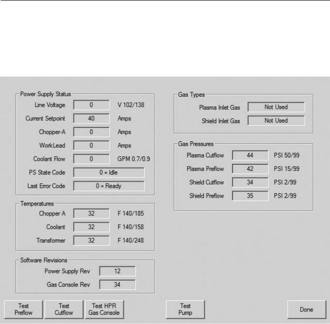
Error codes
Error codes are displayed on the CNC screen. The diagnostic screen shown below is for reference.
|
|
|
|
|
|
5-6 |
|
HPR260 Auto Gas Instruction Manual |
0

MAINTENANCE
Error code troubleshooting (1 of 8)
Error |
|
|
|
|
|
code |
Name |
Description |
Corrective action |
||
No. |
|
|
|
|
|
0 |
No error |
System is ready to run |
None needed |
||
|
|
|
|
||
|
Pump over |
Pump output has |
1. Verify that coolant filters are in good condition. |
||
18 |
exceeded 13.79 Bar (200 |
|
|
||
pressure |
2. Verify that there are no restrictions in the coolant system. |
||||
|
psi). |
||||
|
|
|
|
||
|
|
|
|
|
|
|
|
|
1. |
Verify that the consumable parts are in good condition. |
|
|
|
|
2. |
Verify proper pre-flow and cut-flow settings. |
|
|
|
|
3. |
Perform leak test. |
|
|
|
No current detected from |
4. Verify spark across spark gap. |
||
20 |
No pilot arc |
chopper at ignition and |
5. Inspect CON1 and pilot arc relay for excessive wear. |
||
|
|
before 1-sec timeout. |
6. Perform gas flow test (see Maintenance section). |
||
|
|
|
7. |
Perform torch lead test (see Maintenance section). |
|
|
|
|
8. |
Perform start circuit test (see Maintenance section). |
|
|
|
|
9. |
Perform chopper test (see Maintenance section). |
|
|
|
No current detected on |
1. Verify proper pierce height. |
||
21 |
No arc |
work lead 500 milli- |
2. Verify proper pre-flow and cut-flow settings. |
||
transfer |
seconds after pilot arc |
3. Inspect work lead for damage or loose connections. |
|||
|
|||||
|
|
current was established. |
4. Perform current test (see Maintenance section). |
||
|
|
|
1. |
Verify that the consumable parts are in good condition. |
|
|
|
|
2. |
Verify proper cut-flow gas settings. |
|
24 |
Lost current |
Lost current from chopper |
3. Verify pierce delay time. |
||
|
|
after transfer. |
4. Verify arc did not lose contact with plate while cutting (hole |
||
|
|
|
cutting, scrap cutting, etc). |
||
|
|
|
5. |
Perform chopper test (see Maintenance section). |
|
|
|
|
1. |
Verify that the consumable parts are in good condition. |
|
|
|
|
2. |
Verify proper cut-flow gas settings. |
|
|
|
|
3. |
Verify pierce delay time. |
|
26 |
Lost transfer |
After transfer lost the |
4. Verify arc did not loose contact with plate while cutting (hole |
||
|
|
transfer signal. |
cutting, scrap cutting, etc). |
||
|
|
|
5. |
Inspect work lead for damage or loose connections. |
|
|
|
|
6. Try connecting work lead directly to the plate. |
||
|
|
|
7. |
Perform chopper test (see Maintenance section). |
|
|
|
|
1. |
Verify phase-to-phase voltage to power supply. |
|
|
|
|
2. |
Disconnect power to power supply, remove cover on |
|
|
|
Phase imbalance to |
contactor and inspect contacts for excessive wear. |
||
|
|
3. |
Inspect power cord, contactor, and input to chopper for loose |
||
27 |
Lost phase |
chopper after contactor |
|||
connections. |
|||||
|
|
engaged or while cutting. |
|||
|
|
4. Inspect phase loss fuses on Power Distribution board. |
|||
|
|
|
Replace board if fuses are blown. |
||
|
|
|
5. |
Perform phase loss test (see Maintenance section). |
|
HPR260 Auto Gas Instruction Manual |
5-7 |
1

MAINTENANCE
Error code troubleshooting (2 of 8)
|
Error |
|
|
|
|
|
|
|
code |
Name |
Description |
Corrective action |
|
|
|
|
No. |
|
|
|
|
|
|
|
|
|
|
1. |
Verify that cable No. 5 (power supply to gas console control |
|
|
|
|
|
|
cable) is not damaged and is properly connected to PCB3 and |
|
||
|
|
|
|
the back of the gas console. |
|
||
|
|
|
|
2. |
Verify that cable No. 6 (power supply to gas console power |
|
|
|
|
|
|
cable) is not damaged and is properly connected inside the |
|
||
|
30 |
Gas system |
A failure has occurred in |
power supply and to the back of the gas console. |
|
||
|
error |
the gas system. |
3. |
Verify that D1 (+5 VDC) and D2 (+3.3 VDC) are illuminated |
|
|
|
|
|
|
|||||
|
|
|
|
on PCB2 inside the gas console. These LEDs indicate power to |
|
||
|
|
|
|
PCB2. |
|
||
|
|
|
|
4. |
If power is present at PCB2 and PCB3 and both gas console |
|
|
|
|
|
|
cables are good, then PCB2 or PCB3 has failed. Use the CAN |
|
||
|
|
|
|
tester to verify which board needs to be replaced. |
|
||
|
|
|
|
|
|
|
|
|
|
|
|
1. |
If a mechanical relay is being used to provide the HPR with a |
|
|
|
|
|
|
start signal, this relay is either bouncing when activated or the |
|
||
|
|
|
Start signal was received |
contacts are faulty. Replace the relay. |
|
||
|
|
|
2. |
Inspect interface cable for damage; faulty crimps, or poor |
|
|
|
|
31 |
Start lost |
and then lost before an arc |
|
|||
|
|
|
was established. |
electrical connections. |
|
||
|
|
|
3. |
If interface cable is good and a relay is not driving the start |
|
|
|
|
|
|
|
|
|||
|
|
|
|
input, the CNC is dropping the start signal before a steady state |
|
||
|
|
|
|
arc has been established. |
|
||
|
|
|
|
1. |
Check the interface cable for damage. The hold wires may |
|
|
|
|
|
|
be short-circuiting inside. |
|
||
|
32 |
Hold timeout |
Hold signal was active for |
2. The CNC is maintaining this input, it could be waiting for an |
|
||
|
|
|
longer than 60 seconds. |
IHS complete input from another torch. |
|
||
|
|
|
|
3. |
If CNC interface cable is good and it is a one-torch system, |
|
|
|
|
|
|
change PCB3. |
|
||
|
|
Precharge |
Selection console was not |
This is a warning for a possible gas restriction in the leads. |
|
|
|
|
33 |
able to charge the lines to |
Verify that there are no restrictions in the plasma and shield |
|
|
||
|
time-out |
|
|||||
|
|
the correct value. |
hoses. |
|
|
||
|
|
|
|
||||
|
|
|
Plasma gas pressure |
1. |
Inspect gas supply pressure and volume of gas remaining in |
|
|
|
|
Low plasma |
under lower limit of |
supply tanks. |
|
||
|
44 |
0.34 bar (5 psi) – pre-flow |
2. |
Verify gas regulator settings on gas console. See cut charts. |
|
||
|
gas |
3.45 bar (50 psi) – cutflow |
3. |
See how to set your supply regulators (Installation section). |
|
|
|
|
|
pressure |
|
||||
|
|
(cutting) |
|
|
|
|
|
|
|
|
0.34 bar (5 psi) – cutflow |
4. |
Perform leak test procedure (Maintenance section). |
|
|
|
|
|
(marking) |
|
|||
|
|
|
|
|
|
|
|
|
|
|
|
1. |
Verify gas supply pressure settings. |
|
|
|
|
|
|
2. |
Verify gas regulator settings on gas console with cut chart. |
|
|
|
45 |
High plasma |
Plasma gas pressure over |
3. |
See how to set your supply regulators (Installation section). |
|
|
|
gas |
upper limit of 7.58 bar (110 |
|
|
|
|
|
|
|
pressure |
psi). |
4. |
Solenoid at off-valve is not opening. Verify power to valves, |
|
|
|
|
|
|
disconnect plasma and shield hoses exiting off-valve. If |
|
||
|
|
|
|
pressures decrease a valve is not functioning or no power to |
|
||
|
|
|
|
the valve. |
|
||
|
|
|
|
|
|
|
|
5-8 |
|
|
|
HPR260 Auto Gas Instruction Manual |
|||
1

MAINTENANCE
Error code troubleshooting (3 of 8)
Error
code Name Description Corrective action
No.
1.Verify input-line voltage. Voltage needs to be within 10 % of nominal (120 VAC).
2.Verify fuses on PCB2.
|
|
|
Line voltage is close to or |
3. |
Verify 120 VAC voltage on plug J2.4, pins 3 and 4 on PCB2. |
||
|
|
|
less than the lower limit of |
4. |
Verify voltage on receptacle J2 on PCB2. Should be |
||
46 |
Low line |
102 VAC (120 VAC -15%). |
approximately 1.65 VDC between pins 1 and 2. |
||||
voltage |
The normal lower limit for |
5. |
If AC voltage on J2.4, pins 3 and 4, is greater than 108 VAC |
||||
|
|
|
operation is 108 VAC (120 |
and DC voltage on J2 is less than 1.485 VDC, replace PCB2. |
|||
|
|
|
VAC -10%). |
6. |
If AC voltage on J2.4, pins 3 and 4, is greater than 108 VAC |
||
|
|
|
and DC voltage on J2 is also greater than 1.485 VDC , verify |
||||
|
|
|
|
||||
|
|
|
|
the DC voltage to J3.201 on PCB3. It should equal the voltage |
|||
|
|
|
|
reading on J2. If the DC voltage readings are the same and the |
|||
|
|
|
|
wiring passes continuity tests, replace PCB3. |
|
||
|
|
|
|
1. |
Verify input-line voltage. Voltage needs to be within 10 % of |
||
|
|
|
|
nominal (120 VAC). |
|||
|
|
|
|
2. |
Verify fuses on PCB2. |
||
|
|
|
Line voltage is close to or |
3. |
Verify 120 VAC voltage on plug J2.4, pins 3 and 4 on PCB2. |
||
|
|
|
4. |
Verify voltage on receptacle J2 on PCB2. Should be |
|||
|
|
|
greater than the upper |
approximately 1.65 VDC between pins 1 and 2. |
|||
|
|
High line |
limit of 138 VAC (120 VAC |
||||
47 |
5. |
If AC voltage on J2.4, pins 3 and 4, is less than 132 VAC and |
|||||
|
|
voltage |
+15%). The normal upper |
DC voltage on J2 is greater than 1.815 VDC, replace PCB2. |
|||
|
|
|
limit for operation is 132 |
6. |
If AC voltage on J2.4, pins 3 and 4, is less than 132 VAC and |
||
|
|
|
VAC (120 VAC +10%). |
||||
|
|
|
DC voltage on J2 is less than 1.815 VDC , verify the DC voltage |
||||
|
|
|
|
||||
|
|
|
|
to J3.201 on PCB3. It should equal the voltage reading on J2. If |
|||
|
|
|
|
the DC voltage readings are the same and the wiring passes |
|||
|
|
|
|
continuity tests, replace PCB3. |
|
||
|
|
|
|
1. |
Verify That cable No. 5 (power supply to gas console control |
||
|
|
|
|
cable) is not damaged and is properly connected to PCB3 and |
|||
|
|
|
|
to the back of the gas console. |
|||
|
|
|
|
2. |
Verify that cable No. 6 (power supply to gas console power |
||
|
|
|
An error occurred with the |
cable) is not damaged and is properly connected inside the |
|||
48 |
CAN error |
CAN communications |
power supply and to the back of the gas console. |
||||
between the power supply |
3. |
Verify that D1 (+5 VDC) and D2 (+3.3 VDC) are illuminated |
|||||
|
|
|
|||||
|
|
|
and the gas console. |
on PCB2 inside the gas console. These LEDs indicate power to |
|||
|
|
|
|
PCB2. |
|||
|
|
|
|
4. |
If power is present at PCB2 and PCB3 and both gas console |
||
|
|
|
|
cables are good, then PCB2 or PCB3 has failed. Use the CAN |
|||
|
|
|
|
tester to verify which board needs to be replaced. |
|
||
|
|
|
|
1. |
Stop or clear the cutting program. The plasma start signal to |
||
|
|
|
|
the plasma was not dropped after the last cut. |
|||
|
|
|
|
2. |
Verify that the CNC interface cable is not damaged. |
||
|
|
Start signal |
Plasma start signal input |
3. |
Remove CNC interface cable from PCB3 and look for an |
||
50 |
is on at |
is active during power-up |
open circuit between pins 15 and 34. |
||||
|
|
power-up |
of power supply. |
4. |
If the circuit is closed either the CNC is issuing a plasma start |
||
|
|
|
|
or the CNC interface cable is damage. |
|||
|
|
|
|
5. |
If circuit is open, and LEDN300J is illuminated with CNC |
||
|
|
|
|
Interface cable removed from PCB3, replace PCB3. |
|||
|
|
|
|
|
|
|
|
HPR260 Auto Gas Instruction Manual |
|
5-9 |
|||||
0