

Chapter 5 |
|
|
|
|
Protocol Layer |
|
Wireless Universal Serial Bus Specification, Revision 1.0 |
||
|
|
|
|
|
Setup + No Data Stage |
Idle |
Device |
Host |
|
|
Status Stage |
|
|
|
|
|
|
||
MMC HDR
Smashed MMC
WDTCTA |
Setup Bytes |
Setup Flag = 1B
 ControlStatusFlag = 1B
Direction = IN = 1
ACK or
HNDSK  NAK or
STALL
Idle
MMC HDR
Smashed MMC
WDTCTA
Setup Flag = 0B
 ControlStatusFlag = 1B
Direction = IN = 1
ACK or
HNDSK  NAK or
STALL
Idle
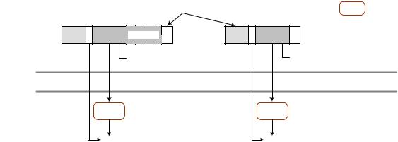
Figure 5-21. Setup w/No Data Stage & Bare Status Stage
To complete a control transfer, the host will transmit an MMC with a WDTCTA block with the Control Status Flag and Direction fields set to a 1B. These settings tell the function control endpoint that the transaction is a status stage transaction for a control transfer. It must transmit a Handshake packet during the protocol time slot. The device must set the rWUSBHeader.Endpoint Direction field to a 1B for a handshake packet transmitted during a control transfer. The Handshake code set by the function control endpoint is set to the following:
NAK indicates that the function has not completed the action requested in the setup data bytes.
ACK indicates the control transfer is complete (and possibly the action requested in the setup data bytes is also complete).
STALL indicates that the function has an error that prevents it from completing the command.
Note, for a control read, the host may use the bvDINAck field of the status stage WDTCTA to deliver the acknowledgement to last data transaction in the data stage. To start a control transfer that does not have a data stage, the host will transmit an MMC with a WDTCTA block encoded for the status stage.
5.5.3 Device Notifications
Device Notifications are small messages transmitted by a device during a DNTS window, see Section 5.2.1.3 for details on requirements for transmitting the actual message packet. The individual device notification packets are not immediately acknowledged by the host. However it is necessary that device notifications be delivered reliably to the host, which generally means that hosts are required to acknowledge device notifications and devices need to track response and retransmit device notifications as necessary. Figure 5-22 illustrates the general model used in this specification for reliable delivery of device notifications. This general model is used as the base building block for all device notification communications. This discussion is intended to be a reference model that meets required behavior. It is not intended to require implementation of the documented states.
113

Chapter 5 |
|
Protocol Layer |
Wireless Universal Serial Bus Specification, Revision 1.0 |
Figure 5-22. General Device Perspective Model for Device Notification Transfers
The Sending Notification state is entered by the device (device context) when a system event (desire to connect to a host, endpoints ready, etc.) occurs that requires a device notification transmission. The device remains in this state, sending the specific Notification to the host until it receives the appropriate (for the Notification type) host response. The frequency of Notification retransmits depend on the type of the Notification and either the specification or implementation policies.
The particular response varies by notification message. For example, some notifications require acknowledgement via information elements in the MMC and some simply require transaction activity to the device. Refer to the detailed descriptions of the individual Device Notifications in Section 7.6 for details on required responses.
5.5.4 Flow Control
USB 2.0 has flow control built into the low-level protocol. The wired protocol requires the host to poll for a change in status once a flow control (NAK) response has been given by the device. USB host controller implementations poll aggressively (often) for a change in data stream readiness. This ‘busy-wait’ polling is extremely expensive in terms of occupying available bandwidth in the wireless environment; therefore, Wireless USB utilizes a less bandwidth consuming method for resuming a data stream after a flow-control event. Note that as with USB 2.0, the initial state of all endpoints after any configuration event is that they are assumed to be in the ‘ready’ state.
A device may respond with a flow control response to any token request. An IN Endpoint will return a handshake packet (NAK) instead of a data packet during the protocol time slot. An OUT Endpoint always returns a handshake packet to acknowledge the data packet(s) received during the data stage protocol time slot. There are two fields of particular interest in the OUT handshake packet, the Handshake Code and the bvAckCode. Table 5-10summarizes the Endpoint responses and the appropriate interpretation.
114
Chapter 5 |
|
Protocol Layer |
Wireless Universal Serial Bus Specification, Revision 1.0 |
Table 5-10. Flow control Event Summary
Host |
|
Device Response |
|
Description |
|
|
|
|
|
IN |
DATA(X) |
|
|
If not end of transfer, host will |
|
|
|
|
advance transfer state and begin |
|
|
|
|
another transaction when |
|
|
|
|
appropriate. |
IN |
bmStatus.Handshake Code |
= NAK |
Flow control response |
|
OUT DATA(X) |
bmStatus.Handshake Code |
= ACK |
More data OK |
|
|
bvAckCode |
≠ 0 |
|
|
OUT DATA(X) |
bmStatus.Handshake Code |
= ACK |
Flow control response. Device |
|
|
bvAckCode |
= 0 |
|
accepted all data transmitted |
|
|
|
|
during the data phase time slot, |
|
|
|
|
but does not have room for more. |
OUT DATA(X) |
bmStatus.Handshake Code |
= NAK |
Flow control response. |
|
|
|
|
|
Device did not accept any data |
|
|
|
|
transmitted during the data phase. |
|
|
|
|
Note, bvAckCode must be a zero. |
When a host receives a flow control response from a function endpoint, it will remove the endpoint data stream from the current active list of endpoints being serviced. In other words, the host will stop polling the function endpoint when it gives a flow control response.
When a Control or Bulk device endpoint is ready to resume the data stream (meaning it has data or space of one or more maximum packet sizes available), the device must send an Endpoints Ready notification message to the host during a DNTS, see Section 7.6.3.
Endpoints Ready notifications must match the encryption mechanism of the associated endpoint. For example, if a device flow controls a control transfer that is not using secure packet encapsulation, the associated Endpoints Ready notification for that endpoint must be transmitted without secure packet encapsulation. A device must not mix unencrypted endpoints with encrypted endpoints in the same Endpoints Ready notification.
A device must not use an Endpoints Ready notification for Isochronous or Interrupt Endpoints. The host will resume transaction traffic to endpoints of these transfer types at the next scheduled service interval. Note that when the host is to resume transactions with an OUT isochronous function endpoint at the next service interval (after a flow control event), it does not have any specific information about how much buffering is available on the function endpoint. For an isochronous function endpoint that has a burst size larger than one the host has no current information about how much buffering is available. Function endpoints must be prepared for a host to resume transactions at the next interval time via a WDTCTA requesting a handshake packet, or a full OUT transaction where the host only transmits one data packet in the burst data phase. In response, the function endpoint provides a handshake packet, which contains the bvAckCode field, indicating to the host how much buffering is available for the next transaction.
115
Chapter 5 |
|
Protocol Layer |
Wireless Universal Serial Bus Specification, Revision 1.0 |
5.6Physical and Media-Access Layer Specific Characteristics
Table 5-11. Wireless USB Protocol Timing Parameters
Parameter |
Symbol |
MAC/PHY Equiv. |
Value |
Units |
|
|
|
|
|
Standard Preamble |
tSTDPREAMBLE |
PLCP Std |
9.375 |
μs |
|
|
Preamble |
|
|
Streaming Preamble |
tSTREAMPREAMBLE |
PLCP Burst |
5.625 |
μs |
|
|
Preamble |
|
|
Maximum interval between |
tMAXMMCINTERVAL |
N/A |
65 |
ms |
MMC packets in a Wireless |
|
|
|
|
USB channel |
|
|
|
|
Maximum Clock Drift |
tMAXDRIFT |
N/A |
1.3107 Note 2 |
μs |
Duration of time slot for a |
tNOTIFICATIONSLOT |
N/A |
24 |
μs |
maximum sized notification |
|
|
|
|
message. |
|
|
|
|
Streaming Inter packet Gap |
tSTREAMIPG |
MIFS |
nominal |
μs |
Calculated guard time |
tGUARDTIME |
N/A |
(2 * MaxDrift) |
μs |
|
|
|
1 μs (d ≤ 25ms) |
|
|
|
|
2 μs |
|
|
|
|
(25ms d ≤ 50ms) |
|
|
|
|
3 μs (d > 50ms) Note 1 |
|
Minimum Inter-slot time |
tINTERSLOTTIME |
MIFS |
MIFS |
μs |
(successive OUT slots) |
|
|
|
|
Minimum transceiver turn |
tBUSTURNTIME |
SIFS |
SIFS |
μs |
time |
|
|
|
|
Minimum Inter-slot time (bus |
tBUSTURNINTERSLOTTIME |
SIFS |
tBUSTURNTIME + tGUARDTIME |
μs |
turn) |
|
|
|
|
Note 1
Note 2
‘d’ is the time between the start of the MMC and the start time for the current packet that must be received. calculated based on 20ppm and a maximum interval of 65535 μs.
116
Chapter 5 |
|
Protocol Layer |
Wireless Universal Serial Bus Specification, Revision 1.0 |
Table 5-12. UWB PHY Related Parameters
Symbol |
Description |
|
|
Value |
Units |
|
|
|
|
||
PHY_TXRate |
This parameter describes the bit transfer rates supported by the |
n/a |
n/a |
||
|
PHY. It is specified as a five-bit field with the following encodings: |
|
|
||
|
Value |
Meaning (Mb/s) |
|
|
|
|
00000B |
53.3 |
|
|
|
|
00001B |
80 |
|
|
|
|
00010B |
106.7 |
|
|
|
|
00011B |
160 |
|
|
|
|
00100B |
200 |
|
|
|
|
00101B |
320 |
|
|
|
|
00110B |
400 |
|
|
|
|
00111B |
480 |
|
|
|
|
01000B |
Reserved |
|
|
|
|
– |
|
|
|
|
|
11111B |
|
|
|
|
Channel |
The channel number encoding maps to a specific band group, TF |
n/a |
n/a |
||
Number |
Code. See reference [4] for details. For this revision of this |
|
|
||
|
specification, only channel numbers for band group one are |
|
|
||
|
required. |
|
|
|
|
|
Channel |
|
|
|
|
|
Number Range |
(Band Group, TF Code) |
|
|
|
|
0 – 8 |
|
Reserved |
|
|
|
9 – 15 |
(1, 1 – 7) |
|
|
|
|
17 – 23 |
(2, 1 – 7) |
|
|
|
|
25 – 31 |
(3, 1 – 7) |
|
|
|
|
33 – 39 |
(4, 1 – 7) |
|
|
|
|
45 – 46 |
(5, 5 – 6) |
|
|
|
SIFS |
Short Interframe Spacing. Maximum TX to RX or RX to TX |
10 |
μs |
||
|
turnaround time allowed. |
|
|
|
|
MIFS |
Minimum Interframe Spacing. Specifically, the minimum time |
1.875 |
μs |
||
|
between successively transmitted packets. For burst-mode |
|
|
||
|
transfers, this is the exact required time between successive |
|
|
||
|
packet transmissions. |
|
|
|
|
PHY Base |
The Base Rate or PHY Base Signaling rate is lowest common |
53.3 |
Mb/s |
||
Signaling Rate |
denominator transmit bit rate defined by the PHY or MAC Layer. |
|
|
||
|
The PHY [4] standard defines 53.3 as the base signaling rate. |
|
|
||
117
Chapter 5 |
|
Protocol Layer |
Wireless Universal Serial Bus Specification, Revision 1.0 |
Table 5-13. MAC Layer Header Field Settings for Wireless USB Protocol Time Slot Packets
Frame Control |
|
|
DestAddr |
SrcAddr |
Sequence |
Access |
|||
|
|
|
|
|
|
|
|
Control |
Information |
|
|
|
|
|
|
|
|
|
|
Bits |
Name |
Value |
|
|
Host to Device |
0000H [4] |
C000H [5] |
||
2:0 |
Version |
000B |
|
|
Device |
Host |
|
|
|
3 |
Secure [1] |
(0 | 1) |
|
|
Address |
DevAddr |
|
|
|
|
|
Device to Host |
|
|
|
||||
5:4 |
ACK Policy |
00B |
|
|
|
|
|
||
8:6 |
Frame Type |
011B |
[2] |
|
Host |
Device |
|
|
|
|
|
DevAddr |
Address |
|
|
||||
12:9 |
Delivery ID |
1XXXB |
|
|
|
||||
|
|
|
|
|
|
||||
|
[3] |
|
|
|
|
|
|
|
|
13 |
Retry |
0B |
|
|
|
|
|
|
|
15:14 |
Reserved |
0B |
|
|
|
|
|
|
|
|
|
|
|
|
|
|
|
|
|
[1]Value of the Secure field depends on the Device State, see Section 7.1 for details.
[2]The value of Frame Type for protocol time slots is Data Frame.
[3]For packet transmissions during protocol time slots, this field (XXX) contains the stream index value assigned by the host to the Wireless USB Channel.
[4]Wireless USB does not use this field, so devices and the host must set this field to the constant value of 0000H.
[5]The MAC Layer requires data packets transmitted during a Private reservation to have the More Data bit set to a one (1B).
Table 5-14. MAC Layer Header Field Settings for Wireless USB MMC Packets
Frame Control |
|
DestAddr |
SrcAddr |
Sequence |
Access |
|
|
|
|
|
|
Control |
Information |
|
|
|
|
|
|
|
Bits |
Name |
Value |
Host to Device |
|
0000H |
8000H |
2:0 |
Version |
000B |
Broadcast |
Host |
|
|
3 |
Secure [1] |
1 |
Cluster |
DevAddr |
|
|
DevAddr |
|
|
|
|||
5:4 |
ACK Policy |
00B |
|
|
|
|
|
|
|
|
|||
8:6 |
Frame Type |
001B [2] |
|
|
|
|
12:9 |
Frame |
1110B |
|
|
|
|
|
Subtype [3] |
|
|
|
|
|
13 |
Retry |
0B |
|
|
|
|
15:14 |
Reserved |
0B |
|
|
|
|
|
|
|
|
|
|
|
[1]See Section 7.5 for rules for using secure packets on MMCs.
[2]The value of Frame Type for MMC packets is Control Frame.
[3]When the Frame Type is Control Frame, then this field indicates the Frame Subtype, which is Applicationspecific Control Frame.
118