- •TABLE OF CONTENTS
- •1.1 Motivation
- •1.2 Design Goals
- •1.3 Objective of the Specification
- •1.4 Scope of the Document
- •1.5 USB Product Compliance
- •1.6 Document Organization
- •2.1 Terms
- •2.2 Conventions:
- •2.3 References
- •3.1 USB System Description
- •3.1.1 Topology
- •3.1.1.1 USB Host
- •3.1.1.2 Wireless USB Devices
- •3.2 Physical Interface
- •3.3 Power Management
- •3.4 Bus Protocol
- •3.5 Robustness
- •3.5.1 Error Handling
- •3.6 Security
- •3.7 System Configuration
- •3.7.1 Attachment of Wireless USB Devices
- •3.7.2 Removal of Wireless USB Devices
- •3.7.3 Bus Enumeration
- •3.8 Data Flow Types
- •3.9 Wireless USB Devices
- •3.9.1 Device Characterizations
- •3.9.2 Devices and MAC Layer
- •3.10 Wireless USB Host: Hardware and Software
- •4.1 Implementer Viewpoints
- •4.2 Communications Topology
- •4.2.1 Physical Topology
- •4.3 Wireless USB Communication Flows
- •4.3.1 Wireless USB Channel Time
- •4.3.2 MMC Transmission Accuracy
- •4.3.3 USB Time across Device Wire Adapters
- •4.3.5 Device Endpoints
- •4.3.6 Wireless USB Information Exchange Methods
- •4.3.7 Device Perspective
- •4.3.7.1 Self Beaconing Devices
- •4.3.7.2 Directed Beaconing Devices
- •4.3.7.3 Non Beaconing Devices
- •4.3.7.4 Selecting A Wireless USB Host
- •4.3.8 Host Perspective
- •4.3.8.1 MAC Layer Compliant Device
- •4.3.8.2 Wireless USB Host
- •4.3.8.3 Host System Management
- •4.3.8.5 Other Host Considerations
- •4.4 Data Transfers
- •4.4.1 Burst Mode Data Phase
- •4.5 Bulk Transfers
- •4.5.1 Bulk Transfer Packet Size and Signaling Rate Constraints
- •4.5.2 Bulk Transfer Channel Access Constraints
- •4.5.3 Bulk Transfer Data Sequences
- •4.6 Interrupt Transfers
- •4.6.1 Low Power Interrupt IN
- •4.6.2 Interrupt Transfer Packet Size and Signaling Rate Constraints
- •4.6.3 Interrupt Transfer Channel Access Constraints
- •4.6.4 Interrupt Transfer Data Sequences
- •4.7 Isochronous Transfers
- •4.7.1 Isochronous Transfer Packet Size and Signaling Rate Constraints
- •4.7.2 Isochronous Transfer Channel Access Constraints
- •4.7.3 Isochronous Transfer Data Sequences
- •4.7.4 Isochronous Endpoint Host System Admission Decisions
- •4.7.5 Isochronous Data Discards and Use of Isochronous Packet Discard IE
- •4.8 Control Transfers
- •4.8.1 Control Transfer Packet Size and Signaling Rate Constraints
- •4.8.2 Control Transfer Channel Access Constraints
- •4.8.3 Control Transfer Data Sequences
- •4.8.4 Data Loopback Commands
- •4.9 Device Notifications
- •4.10 Media Reliability Considerations
- •4.10.1 Transmit Power Control
- •4.10.2 Adjustments to Data Phase Packet Payload Sizes
- •4.10.3 Adjustments to Transmit Bit Rate
- •4.10.4 Changing PHY Channel
- •4.10.5 Host Schedule Control
- •4.10.6 Dynamic Bandwidth Interface Control
- •4.11 Special Considerations for Isochronous Transfers
- •4.11.1 Summary Of Key Features Of USB Wired Isochrony
- •4.11.1.1 Wireless Service Intervals
- •4.11.2 UWB Media Characteristics
- •4.11.2.1 Superframe Layout
- •4.11.2.2 Worst Case Superframe Layout – Service Interval Bounds.
- •4.11.2.3 Wireless Packet Error Rates
- •4.11.3 Wireless USB Isochronous Transfer Level Protocol
- •4.11.4 Wireless USB Isochronous IN Example
- •4.11.5 Wireless USB Isochronous OUT Example
- •4.11.6 Choosing an Isochronous IN or Isochronous OUT Endpoint Buffer Size
- •4.11.7 Isochronous OUT endpoint receiver implementation options
- •4.11.7.1 Presentation Time aware implementation
- •4.11.7.2 Presentation time aware implementation with “false” acknowledgement
- •4.11.7.3 Presentation time unaware implementations
- •4.11.8 Synchronization
- •4.11.8.1 Synchronizing a Stream Start Time
- •4.11.9 Error Handling Details
- •4.11.9.1 Reporting Data Discarded At the Transmitter
- •4.11.9.2 Discarding Data during A Burst
- •4.11.9.3 Application Handling of Discards
- •4.12 Device Reset
- •4.13 Connection Process
- •4.13.1 Reconnection Process
- •4.14 Disconnect
- •4.15 Security Mechanisms
- •4.15.1 Connection Lifetime
- •4.15.2 Host Security Considerations
- •4.15.2.1 CHID Selection
- •4.15.2.2 CDID Selection
- •4.16 Wireless USB Power Management
- •4.16.1 Device Power Management
- •4.16.1.1 Device Sleep
- •4.16.1.2 Device Wakeup
- •4.16.2 Host Power Management
- •4.16.2.1 Channel Stop
- •4.16.2.2 Remote Wakeup
- •4.16.2.3 Channel Start
- •4.17 Dual Role Devices (DRD)
- •4.17.2 Pairing P2P-DRD to establish reverse link
- •5.1 Packet Formats
- •5.2 Wireless USB Transaction Groups
- •5.2.1 Wireless USB Channel Time Allocation Information Elements
- •5.3 Transaction Group Timing Constraints
- •5.3.1 Streaming-Mode Inter-packet Constraints for the PHY
- •5.3.2 Protocol Synchronization
- •5.4 Data Burst Synchronization and Retry
- •5.5 Wireless USB Transactions
- •5.5.1 Isochronous Transactions
- •5.5.2 Control Transfers
- •5.5.3 Device Notifications
- •5.5.4 Flow Control
- •6.1 Introduction
- •6.1.1 Goal of USB Security
- •6.1.2 Security and USB
- •6.2 Overview
- •6.2.1 Base of Trust
- •6.2.2 Preserve the Nature of the USB Device Model
- •6.2.3 Implementation of Security Extensions
- •6.2.4 Encryption Methods
- •6.2.5 Message Format
- •6.2.6 Encryption Keys
- •6.2.6.1 Master Keys
- •6.2.6.2 Session Keys
- •6.2.7 Correct key determination
- •6.2.8 Replay Prevention
- •6.2.9 Secure Packet Reception
- •6.2.10 General Connection Model
- •6.2.10.1 Connection Context
- •6.2.10.2 Connection Lifetime
- •6.2.10.3 New Connection
- •6.2.10.4 Connection
- •6.2.10.5 Reconnection
- •6.2.10.6 Revocation
- •6.2.10.8 Diagnostic Support
- •6.2.10.9 Mutual Authentication
- •6.2.11 Key Management
- •6.2.11.1 PTK Management
- •6.2.11.2 GTK Management
- •6.3 Association and Authentication
- •6.3.1 Connection and Reconnection Requests
- •6.3.2 Authentication
- •6.3.2.1 Authentication Related Device Capabilities
- •6.3.2.2 Ceremonies
- •6.4.1 CCM nonce Construction
- •6.4.2 l(m) and l(a) Calculation
- •6.4.3 Counter-mode Bx Blocks
- •6.4.4 Encryption Ax Blocks
- •6.5.1 Key Derivation
- •6.5.2 Out-of-band MIC Generation
- •6.5.3 Example Random Number Generation
- •7.1 Wireless USB Device States
- •7.1.1 UnConnected
- •7.1.2 UnAuthenticated
- •7.1.3 Authenticated
- •7.1.4 Reconnecting
- •7.2 Generic Wireless USB Device Operations
- •7.3 Standard Wireless USB Device Requests
- •7.3.1 Wireless USB Extensions to Standard Requests
- •7.3.1.1 Clear Feature
- •7.3.1.2 Get Status
- •7.3.1.3 Set Address
- •7.3.1.4 Set Feature
- •7.3.1.5 Set Interface DS
- •7.3.1.6 Set WUSB Data
- •7.3.1.7 Data Loopback Write
- •7.3.1.8 DATA Loopback Read
- •7.3.2 Security-related Requests
- •7.3.2.1 Get Security Descriptor
- •7.3.2.2 Set Encryption
- •7.3.2.3 Get Encryption
- •7.3.2.4 Key Management
- •7.3.2.6 Set Security Data
- •7.3.2.7 Get Security Data
- •7.4 Standard Wireless USB Descriptors
- •7.4.1 Device Level Descriptors
- •7.4.1.1 Wireless USB Device Capabilities – UWB
- •7.4.2 Configuration
- •7.4.3 Endpoint
- •7.4.4 Wireless USB Endpoint Companion
- •7.4.5 Security-Related Descriptors
- •7.4.5.1 Security Descriptor
- •7.4.5.2 Key Descriptor
- •7.5 Wireless USB Channel Information Elements
- •7.5.1 Wireless USB Connect Acknowledge IE
- •7.5.2 Wireless USB Host Information IE
- •7.5.3 Wireless USB Channel Change Announcement IE
- •7.5.4 Wireless USB Device Disconnect IE
- •7.5.5 Wireless USB Host Disconnect IE
- •7.5.6 Wireless USB Release Channel IE
- •7.5.7 Wireless USB Work IE
- •7.5.8 Wireless USB Channel Stop IE
- •7.5.9 Wireless USB Device Keepalive IE
- •7.5.10 Wireless USB Isochronous Packet Discard IE
- •7.5.11 Wireless USB Reset Device IE
- •7.5.12 Wireless USB Transmit Packet Adjustment IE
- •7.6 Device Notifications
- •7.6.1 Device Connect (DN_Connect)
- •7.6.1.1 Connect Request
- •7.6.1.2 Reconnect Request
- •7.6.2 Device Disconnect (DN_Disconnect)
- •7.6.3 Device Endpoints Ready (DN_EPRdy)
- •7.6.4 Device MAS Availability Changed (DN_MASAvailChanged)
- •7.6.5 Device Sleep (DN_Sleep)
- •7.6.6 Remote Wakeup (DN_RemoteWakeup)
- •7.6.7 Device Alive (DN_Alive)
- •8.1 Operational Model
- •8.1.1 Functional Characteristics
- •8.1.2 Data Transfer Interface
- •8.1.3 Remote Pipe
- •8.1.4 Wire Adapter Functional Blocks
- •8.1.5 Downstream Port(s)
- •8.1.6 Upstream Port
- •8.1.7 Downstream Host Controller
- •8.1.8 Upstream Endpoint Controller
- •8.1.9 Remote Pipe Controller
- •8.1.9.1 RPipe Descriptor
- •8.1.9.2 Bulk OUT Overview
- •8.1.9.3 Bulk IN Overview
- •8.1.9.4 Control Transfer Overview
- •8.1.9.5 Interrupt Transfer Overview
- •8.1.9.6 Isochronous Transfer Overview
- •8.1.10 Suspend and Resume
- •8.1.10.1 DWA Suspend and Resume
- •8.1.10.2 HWA Suspend and Resume
- •8.1.11 Reset Behavior
- •8.1.12 Device Control
- •8.1.13 Buffer Configuration
- •8.2 Descriptors
- •8.3 Requests
- •8.3.1 Wire Adapter Class-Specific Requests
- •8.3.1.1 Abort RPipe
- •8.3.1.2 Clear RPipe Feature
- •8.3.1.3 Clear Wire Adapter Feature
- •8.3.1.4 Get RPipe Descriptor
- •8.3.1.5 Get RPipe Status
- •8.3.1.6 Get Wire Adapter Status
- •8.3.1.7 Set RPipe Descriptor
- •8.3.1.8 Set RPipe Feature
- •8.3.1.9 Set Wire Adapter Feature
- •8.3.1.10 Reset RPipe
- •8.3.2 Notification Information
- •8.3.3 Transfer Requests
- •8.3.3.1 Control Transfers
- •8.3.3.2 Bulk and Interrupt Transfers
- •8.3.3.3 Transfer Completion Notification
- •8.3.3.4 Transfer Result
- •8.3.3.5 Abort Transfer
- •8.4 DWA Interfaces, Descriptors and Control
- •8.4.1 DWA Isochronous Streaming Interface
- •8.4.2 DWA Isochronous Streaming Overview
- •8.4.3 DWA Descriptors
- •8.4.3.1 Device Descriptor
- •8.4.3.2 Binary Device Object (BOS) Descriptor
- •8.4.3.3 Configuration Descriptor
- •8.4.3.4 Security Descriptors
- •8.4.3.5 Interface Association Descriptor
- •8.4.3.6 Data Transfer Interface Descriptor
- •8.4.3.7 Wire Adapter Class Descriptor
- •8.4.3.8 Notification Endpoint Descriptor
- •8.4.3.9 Notification Endpoint Companion Descriptor
- •8.4.3.10 Data Transfer Write Endpoint Descriptor
- •8.4.3.11 Data Transfer Write Endpoint Companion Descriptor
- •8.4.3.12 Data Transfer Read Endpoint Descriptor
- •8.4.3.13 Data Transfer Read Endpoint Companion Descriptor
- •8.4.3.14 Isochronous Streaming Interface Descriptor
- •8.4.3.15 Isochronous Streaming OUT Endpoint Descriptor
- •8.4.3.16 Isochronous Streaming OUT Endpoint Companion Descriptor
- •8.4.3.17 Isochronous Streaming IN Endpoint Descriptor
- •8.4.3.18 Isochronous Streaming IN Endpoint Companion Descriptor
- •8.4.3.19 Wire Adapter RPipe Descriptor
- •8.4.4 DWA Specific Requests
- •8.4.4.1 Clear Port Feature
- •8.4.4.2 Get Port Status
- •8.4.4.3 Set Isochronous Endpoint Attributes
- •8.4.4.4 Set Port Feature
- •8.4.5 DWA Notification Information
- •8.4.5.1 Remote Wake
- •8.4.5.2 Port Status Change
- •8.4.6 DWA Isochronous Transfers
- •8.4.6.1 DWA Isochronous OUT Responsibilities
- •8.4.6.2 DWA Isochronous IN Responsibilities
- •8.5 HWA Interfaces, Descriptors and Control
- •8.5.1 HWA Isochronous Streaming Overview
- •8.5.2 HWA Descriptors
- •8.5.2.1 Device Descriptor
- •8.5.2.2 Device_Qualifier Descriptor
- •8.5.2.3 Configuration Descriptor
- •8.5.2.4 Other_Speed_Configuration Descriptor
- •8.5.2.5 Security Descriptors
- •8.5.2.6 Data Transfer Interface Descriptor
- •8.5.2.7 Wire Adapter Class Descriptor
- •8.5.2.8 Notification Endpoint Descriptor
- •8.5.2.9 Data Transfer Write Endpoint Descriptor
- •8.5.2.10 Data Transfer Read Endpoint Descriptor
- •8.5.2.11 Wire Adapter RPipe Descriptor
- •8.5.3 HWA Specific Requests
- •8.5.3.2 Get BPST Adjustment
- •8.5.3.3 Get BPST Time
- •8.5.3.4 Get WUSB Time
- •8.5.3.5 Remove MMC IE
- •8.5.3.6 Set Device Encryption
- •8.5.3.7 Set Device Info
- •8.5.3.8 Set Device Key
- •8.5.3.9 Set Group Key
- •8.5.3.10 Set Num DNTS Slots
- •8.5.3.11 Set WUSB Cluster ID
- •8.5.3.12 Set WUSB MAS
- •8.5.3.13 Set WUSB Stream Index
- •8.5.3.14 WUSB Channel Stop
- •8.5.4 HWA Notification Information
- •8.5.4.1 BPST Adjustment Change
- •8.5.4.2 DN Received Notification
- •8.5.5 HWA Isochronous Transfers
- •8.5.5.1 HWA Isochronous OUT Responsibilities
- •8.5.5.2 HWA Isochronous IN Responsibilities
- •8.5.5.3 HWA Isochronous Transfer Completion
- •8.6 Radio Control Interface
- •8.6.1 Radio Control Descriptors
- •8.6.1.1 Radio Control Interface Descriptor
- •8.6.1.2 Radio Control Interface Class Descriptor
- •8.6.1.3 Radio Control Interrupt Endpoint Descriptor
- •8.6.2 Radio Control Command
- •8.6.2.1 Channel Change
- •8.6.2.2 Device Address Management
- •8.6.2.4 Reset
- •8.6.2.5 Scan
- •8.6.2.6 Set Beacon Filter
- •8.6.2.9 Set Notification Filter
- •8.6.2.10 Set TX Power
- •8.6.2.11 Sleep
- •8.6.2.12 Start Beaconing
- •8.6.2.13 Stop Beaconing
- •8.6.3 Radio Control Notifications
- •8.6.3.1 Application-specific Probe IE Received Notification
- •8.6.3.2 Beacon Received Notification
- •8.6.3.3 Beacon Size Notification
- •8.6.3.4 BPOIE Change Notification
- •8.6.3.5 BP Slot Change Notification
- •8.6.3.6 BP Switch IE Received Notification
- •8.6.3.7 Device Address Conflict Notification
- •8.6.3.8 DRP Availability Changed Notification
- •8.6.3.9 DRP Notification
- •A.1 Key Derivation
- •A.2 Handshake MIC calculation
- •A.3 Secure MMC (EO = payload length)
- •A.4 Data IN from device (EO = 2)
- •B.1 Descriptors for DWA
- •B.2 Descriptors for HWA
Chapter 4 |
|
Data Flow Model |
Wireless Universal Serial Bus Specification, Revision 1.0 |
Chapter 4
Data Flow Model
This chapter presents high-level information on how data and information moves across the Wireless USB ‘Link’. The information in this chapter affects all implementers. The information presented is above the signaling and protocol definition(s) of the system. Consult Chapter 5 for details on the low-level protocol. This chapter provides framework overview information that is further expanded in Chapter 7. All implementers should read this chapter so they understand the key concepts of Wireless USB.
4.1Implementer Viewpoints
Wireless USB is very similar to USB 2.0 in that it provides communication services between a Wireless USB Host and attached Wireless USB Devices. The Wireless USB communication model view preserves the USB 2.0 layered architecture and basic components of the communication flow (i.e. point-to-point, same transfer types, etc., See Section 5 in the Universal Serial Bus Specification Revision 2.0).
This chapter describes the differences (from USB 2.0) of how data and control information is communicated between a Wireless USB Host and its attached Wireless USB Devices. In order to understand Wireless USB data flow, the following concepts are useful:
•Communications Topology: Section 4.2 reviews the USB communications topology including differences in the physical topology from USB 2.0.
•Communication Flow Models: Section 4.3 defines the general mechanisms for accomplishing information exchanges, including data and control information, between a host and devices.
•Data Transfers: Section 4.4 provides an overview of how data transfers work in Wireless USB and subsequent sections define the operating constraints for each Wireless USB transfer type.
•Device Notifications: Section 4.9 provides an overview of Device Notifications, a feature which allows a device to asynchronously notify its host of events or status on the device.
•Media Reliability: Section 4.10 summarizes the information and mechanisms available in Wireless USB that a host might use to manage the reliability of the wireless data flows.
•Isochronous transfer model: Section 4.11 provides a detailed model for how isochronous data streams work over a Wireless USB channel.
•Connection Process: Section 4.13 outlines the basic connection process and introduces the basic mechanisms for getting devices connected to hosts.
•Security Mechanisms: Section 4.15 summaries the security features provided by Wireless USB.
•Power Management: Wireless enables mobility and mobility implies battery powered devices. Section 4.16 summarizes the power management model and features provided by Wireless USB.
4.2Communications Topology
The general communications topology of Wireless USB is identical to that used in USB 2.0 (see Figure 4-1). The obvious advantage of this is that many existing USB 2.0 functional components (in hosts and devices) continue to work without modification when the physical layer components supporting USB 2.0 are replaced with those supporting Wireless USB. The delta change from USB 2.0 to Wireless USB is illustrated to the righthand side of Figure 4-1. The Function Layer is (almost) completely the same. The only difference is the isochronous transfer model has some enhancements to allow functions to react to the increased unreliability of the “Bus Layer”. The Device Layer includes a small number of framework extensions to support security (see
19
Chapter 4 |
|
Data Flow Model |
Wireless Universal Serial Bus Specification, Revision 1.0 |
below) and management commands required to manage devices on the wireless media. Finally, the Bus Layer includes significant changes to provide an efficient, secure communication service over a wireless media.
The copper wire in USB 2.0 provides significant value with regards to security of data communications. The User knows which host the device is associated with because the device has to be physically plugged into a receptacle and the wire provides a specific path for data communications flow between a host and devices that cannot be casually observed by devices not purposely connected. Replacing the physical layer copper with a radio results in ambiguity about the actual association between devices and hosts, and also exposes data communication flows to all devices within listening range. In other words, the loss of the wire results in a significant loss of security which must be replaced by other mechanisms in order for Wireless USB to be a viable and usable technology.
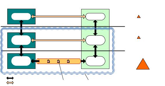
Wireless USB defines processes which allow a device and host to exchange the information required to establish a Secure Relationship (see Section 6.2.8). After a secure relationship has been established, the host and device have the necessary information required to support data encryption for “over the air” communications. Figure 4-1 illustrates how the standard USB data communications flow topology is extended for Wireless USB to include the concept of a secure relationship between a host and device and also illustrates that over-the-air data communications are encrypted. Notice that these new features extend only up to the device layer of the topology, allowing existing applications and device functions to exist and work without modification.
Figure 4-1. Wireless USB Data Communications Topology
Another side-effect of replacing the copper interconnect with a radio is that all low-level signaling events need to be provided mechanisms in the data flow topology that achieve equivalent functions. These include replacements for signaling events such as Connect, Disconnect and Resume.
4.2.1Physical Topology
Wireless USB Devices are not physically attached to a Wireless USB Host. Devices within radio range of a host establish a secure relationship with the host before application data communications are allowed. A host and its associated devices are referred to as a Wireless USB Cluster. A Wireless USB Cluster is comprised of a Wireless USB Host and all the Wireless USB Devices that it directly manages.
20