- •TABLE OF CONTENTS
- •1.1 Motivation
- •1.2 Design Goals
- •1.3 Objective of the Specification
- •1.4 Scope of the Document
- •1.5 USB Product Compliance
- •1.6 Document Organization
- •2.1 Terms
- •2.2 Conventions:
- •2.3 References
- •3.1 USB System Description
- •3.1.1 Topology
- •3.1.1.1 USB Host
- •3.1.1.2 Wireless USB Devices
- •3.2 Physical Interface
- •3.3 Power Management
- •3.4 Bus Protocol
- •3.5 Robustness
- •3.5.1 Error Handling
- •3.6 Security
- •3.7 System Configuration
- •3.7.1 Attachment of Wireless USB Devices
- •3.7.2 Removal of Wireless USB Devices
- •3.7.3 Bus Enumeration
- •3.8 Data Flow Types
- •3.9 Wireless USB Devices
- •3.9.1 Device Characterizations
- •3.9.2 Devices and MAC Layer
- •3.10 Wireless USB Host: Hardware and Software
- •4.1 Implementer Viewpoints
- •4.2 Communications Topology
- •4.2.1 Physical Topology
- •4.3 Wireless USB Communication Flows
- •4.3.1 Wireless USB Channel Time
- •4.3.2 MMC Transmission Accuracy
- •4.3.3 USB Time across Device Wire Adapters
- •4.3.5 Device Endpoints
- •4.3.6 Wireless USB Information Exchange Methods
- •4.3.7 Device Perspective
- •4.3.7.1 Self Beaconing Devices
- •4.3.7.2 Directed Beaconing Devices
- •4.3.7.3 Non Beaconing Devices
- •4.3.7.4 Selecting A Wireless USB Host
- •4.3.8 Host Perspective
- •4.3.8.1 MAC Layer Compliant Device
- •4.3.8.2 Wireless USB Host
- •4.3.8.3 Host System Management
- •4.3.8.5 Other Host Considerations
- •4.4 Data Transfers
- •4.4.1 Burst Mode Data Phase
- •4.5 Bulk Transfers
- •4.5.1 Bulk Transfer Packet Size and Signaling Rate Constraints
- •4.5.2 Bulk Transfer Channel Access Constraints
- •4.5.3 Bulk Transfer Data Sequences
- •4.6 Interrupt Transfers
- •4.6.1 Low Power Interrupt IN
- •4.6.2 Interrupt Transfer Packet Size and Signaling Rate Constraints
- •4.6.3 Interrupt Transfer Channel Access Constraints
- •4.6.4 Interrupt Transfer Data Sequences
- •4.7 Isochronous Transfers
- •4.7.1 Isochronous Transfer Packet Size and Signaling Rate Constraints
- •4.7.2 Isochronous Transfer Channel Access Constraints
- •4.7.3 Isochronous Transfer Data Sequences
- •4.7.4 Isochronous Endpoint Host System Admission Decisions
- •4.7.5 Isochronous Data Discards and Use of Isochronous Packet Discard IE
- •4.8 Control Transfers
- •4.8.1 Control Transfer Packet Size and Signaling Rate Constraints
- •4.8.2 Control Transfer Channel Access Constraints
- •4.8.3 Control Transfer Data Sequences
- •4.8.4 Data Loopback Commands
- •4.9 Device Notifications
- •4.10 Media Reliability Considerations
- •4.10.1 Transmit Power Control
- •4.10.2 Adjustments to Data Phase Packet Payload Sizes
- •4.10.3 Adjustments to Transmit Bit Rate
- •4.10.4 Changing PHY Channel
- •4.10.5 Host Schedule Control
- •4.10.6 Dynamic Bandwidth Interface Control
- •4.11 Special Considerations for Isochronous Transfers
- •4.11.1 Summary Of Key Features Of USB Wired Isochrony
- •4.11.1.1 Wireless Service Intervals
- •4.11.2 UWB Media Characteristics
- •4.11.2.1 Superframe Layout
- •4.11.2.2 Worst Case Superframe Layout – Service Interval Bounds.
- •4.11.2.3 Wireless Packet Error Rates
- •4.11.3 Wireless USB Isochronous Transfer Level Protocol
- •4.11.4 Wireless USB Isochronous IN Example
- •4.11.5 Wireless USB Isochronous OUT Example
- •4.11.6 Choosing an Isochronous IN or Isochronous OUT Endpoint Buffer Size
- •4.11.7 Isochronous OUT endpoint receiver implementation options
- •4.11.7.1 Presentation Time aware implementation
- •4.11.7.2 Presentation time aware implementation with “false” acknowledgement
- •4.11.7.3 Presentation time unaware implementations
- •4.11.8 Synchronization
- •4.11.8.1 Synchronizing a Stream Start Time
- •4.11.9 Error Handling Details
- •4.11.9.1 Reporting Data Discarded At the Transmitter
- •4.11.9.2 Discarding Data during A Burst
- •4.11.9.3 Application Handling of Discards
- •4.12 Device Reset
- •4.13 Connection Process
- •4.13.1 Reconnection Process
- •4.14 Disconnect
- •4.15 Security Mechanisms
- •4.15.1 Connection Lifetime
- •4.15.2 Host Security Considerations
- •4.15.2.1 CHID Selection
- •4.15.2.2 CDID Selection
- •4.16 Wireless USB Power Management
- •4.16.1 Device Power Management
- •4.16.1.1 Device Sleep
- •4.16.1.2 Device Wakeup
- •4.16.2 Host Power Management
- •4.16.2.1 Channel Stop
- •4.16.2.2 Remote Wakeup
- •4.16.2.3 Channel Start
- •4.17 Dual Role Devices (DRD)
- •4.17.2 Pairing P2P-DRD to establish reverse link
- •5.1 Packet Formats
- •5.2 Wireless USB Transaction Groups
- •5.2.1 Wireless USB Channel Time Allocation Information Elements
- •5.3 Transaction Group Timing Constraints
- •5.3.1 Streaming-Mode Inter-packet Constraints for the PHY
- •5.3.2 Protocol Synchronization
- •5.4 Data Burst Synchronization and Retry
- •5.5 Wireless USB Transactions
- •5.5.1 Isochronous Transactions
- •5.5.2 Control Transfers
- •5.5.3 Device Notifications
- •5.5.4 Flow Control
- •6.1 Introduction
- •6.1.1 Goal of USB Security
- •6.1.2 Security and USB
- •6.2 Overview
- •6.2.1 Base of Trust
- •6.2.2 Preserve the Nature of the USB Device Model
- •6.2.3 Implementation of Security Extensions
- •6.2.4 Encryption Methods
- •6.2.5 Message Format
- •6.2.6 Encryption Keys
- •6.2.6.1 Master Keys
- •6.2.6.2 Session Keys
- •6.2.7 Correct key determination
- •6.2.8 Replay Prevention
- •6.2.9 Secure Packet Reception
- •6.2.10 General Connection Model
- •6.2.10.1 Connection Context
- •6.2.10.2 Connection Lifetime
- •6.2.10.3 New Connection
- •6.2.10.4 Connection
- •6.2.10.5 Reconnection
- •6.2.10.6 Revocation
- •6.2.10.8 Diagnostic Support
- •6.2.10.9 Mutual Authentication
- •6.2.11 Key Management
- •6.2.11.1 PTK Management
- •6.2.11.2 GTK Management
- •6.3 Association and Authentication
- •6.3.1 Connection and Reconnection Requests
- •6.3.2 Authentication
- •6.3.2.1 Authentication Related Device Capabilities
- •6.3.2.2 Ceremonies
- •6.4.1 CCM nonce Construction
- •6.4.2 l(m) and l(a) Calculation
- •6.4.3 Counter-mode Bx Blocks
- •6.4.4 Encryption Ax Blocks
- •6.5.1 Key Derivation
- •6.5.2 Out-of-band MIC Generation
- •6.5.3 Example Random Number Generation
- •7.1 Wireless USB Device States
- •7.1.1 UnConnected
- •7.1.2 UnAuthenticated
- •7.1.3 Authenticated
- •7.1.4 Reconnecting
- •7.2 Generic Wireless USB Device Operations
- •7.3 Standard Wireless USB Device Requests
- •7.3.1 Wireless USB Extensions to Standard Requests
- •7.3.1.1 Clear Feature
- •7.3.1.2 Get Status
- •7.3.1.3 Set Address
- •7.3.1.4 Set Feature
- •7.3.1.5 Set Interface DS
- •7.3.1.6 Set WUSB Data
- •7.3.1.7 Data Loopback Write
- •7.3.1.8 DATA Loopback Read
- •7.3.2 Security-related Requests
- •7.3.2.1 Get Security Descriptor
- •7.3.2.2 Set Encryption
- •7.3.2.3 Get Encryption
- •7.3.2.4 Key Management
- •7.3.2.6 Set Security Data
- •7.3.2.7 Get Security Data
- •7.4 Standard Wireless USB Descriptors
- •7.4.1 Device Level Descriptors
- •7.4.1.1 Wireless USB Device Capabilities – UWB
- •7.4.2 Configuration
- •7.4.3 Endpoint
- •7.4.4 Wireless USB Endpoint Companion
- •7.4.5 Security-Related Descriptors
- •7.4.5.1 Security Descriptor
- •7.4.5.2 Key Descriptor
- •7.5 Wireless USB Channel Information Elements
- •7.5.1 Wireless USB Connect Acknowledge IE
- •7.5.2 Wireless USB Host Information IE
- •7.5.3 Wireless USB Channel Change Announcement IE
- •7.5.4 Wireless USB Device Disconnect IE
- •7.5.5 Wireless USB Host Disconnect IE
- •7.5.6 Wireless USB Release Channel IE
- •7.5.7 Wireless USB Work IE
- •7.5.8 Wireless USB Channel Stop IE
- •7.5.9 Wireless USB Device Keepalive IE
- •7.5.10 Wireless USB Isochronous Packet Discard IE
- •7.5.11 Wireless USB Reset Device IE
- •7.5.12 Wireless USB Transmit Packet Adjustment IE
- •7.6 Device Notifications
- •7.6.1 Device Connect (DN_Connect)
- •7.6.1.1 Connect Request
- •7.6.1.2 Reconnect Request
- •7.6.2 Device Disconnect (DN_Disconnect)
- •7.6.3 Device Endpoints Ready (DN_EPRdy)
- •7.6.4 Device MAS Availability Changed (DN_MASAvailChanged)
- •7.6.5 Device Sleep (DN_Sleep)
- •7.6.6 Remote Wakeup (DN_RemoteWakeup)
- •7.6.7 Device Alive (DN_Alive)
- •8.1 Operational Model
- •8.1.1 Functional Characteristics
- •8.1.2 Data Transfer Interface
- •8.1.3 Remote Pipe
- •8.1.4 Wire Adapter Functional Blocks
- •8.1.5 Downstream Port(s)
- •8.1.6 Upstream Port
- •8.1.7 Downstream Host Controller
- •8.1.8 Upstream Endpoint Controller
- •8.1.9 Remote Pipe Controller
- •8.1.9.1 RPipe Descriptor
- •8.1.9.2 Bulk OUT Overview
- •8.1.9.3 Bulk IN Overview
- •8.1.9.4 Control Transfer Overview
- •8.1.9.5 Interrupt Transfer Overview
- •8.1.9.6 Isochronous Transfer Overview
- •8.1.10 Suspend and Resume
- •8.1.10.1 DWA Suspend and Resume
- •8.1.10.2 HWA Suspend and Resume
- •8.1.11 Reset Behavior
- •8.1.12 Device Control
- •8.1.13 Buffer Configuration
- •8.2 Descriptors
- •8.3 Requests
- •8.3.1 Wire Adapter Class-Specific Requests
- •8.3.1.1 Abort RPipe
- •8.3.1.2 Clear RPipe Feature
- •8.3.1.3 Clear Wire Adapter Feature
- •8.3.1.4 Get RPipe Descriptor
- •8.3.1.5 Get RPipe Status
- •8.3.1.6 Get Wire Adapter Status
- •8.3.1.7 Set RPipe Descriptor
- •8.3.1.8 Set RPipe Feature
- •8.3.1.9 Set Wire Adapter Feature
- •8.3.1.10 Reset RPipe
- •8.3.2 Notification Information
- •8.3.3 Transfer Requests
- •8.3.3.1 Control Transfers
- •8.3.3.2 Bulk and Interrupt Transfers
- •8.3.3.3 Transfer Completion Notification
- •8.3.3.4 Transfer Result
- •8.3.3.5 Abort Transfer
- •8.4 DWA Interfaces, Descriptors and Control
- •8.4.1 DWA Isochronous Streaming Interface
- •8.4.2 DWA Isochronous Streaming Overview
- •8.4.3 DWA Descriptors
- •8.4.3.1 Device Descriptor
- •8.4.3.2 Binary Device Object (BOS) Descriptor
- •8.4.3.3 Configuration Descriptor
- •8.4.3.4 Security Descriptors
- •8.4.3.5 Interface Association Descriptor
- •8.4.3.6 Data Transfer Interface Descriptor
- •8.4.3.7 Wire Adapter Class Descriptor
- •8.4.3.8 Notification Endpoint Descriptor
- •8.4.3.9 Notification Endpoint Companion Descriptor
- •8.4.3.10 Data Transfer Write Endpoint Descriptor
- •8.4.3.11 Data Transfer Write Endpoint Companion Descriptor
- •8.4.3.12 Data Transfer Read Endpoint Descriptor
- •8.4.3.13 Data Transfer Read Endpoint Companion Descriptor
- •8.4.3.14 Isochronous Streaming Interface Descriptor
- •8.4.3.15 Isochronous Streaming OUT Endpoint Descriptor
- •8.4.3.16 Isochronous Streaming OUT Endpoint Companion Descriptor
- •8.4.3.17 Isochronous Streaming IN Endpoint Descriptor
- •8.4.3.18 Isochronous Streaming IN Endpoint Companion Descriptor
- •8.4.3.19 Wire Adapter RPipe Descriptor
- •8.4.4 DWA Specific Requests
- •8.4.4.1 Clear Port Feature
- •8.4.4.2 Get Port Status
- •8.4.4.3 Set Isochronous Endpoint Attributes
- •8.4.4.4 Set Port Feature
- •8.4.5 DWA Notification Information
- •8.4.5.1 Remote Wake
- •8.4.5.2 Port Status Change
- •8.4.6 DWA Isochronous Transfers
- •8.4.6.1 DWA Isochronous OUT Responsibilities
- •8.4.6.2 DWA Isochronous IN Responsibilities
- •8.5 HWA Interfaces, Descriptors and Control
- •8.5.1 HWA Isochronous Streaming Overview
- •8.5.2 HWA Descriptors
- •8.5.2.1 Device Descriptor
- •8.5.2.2 Device_Qualifier Descriptor
- •8.5.2.3 Configuration Descriptor
- •8.5.2.4 Other_Speed_Configuration Descriptor
- •8.5.2.5 Security Descriptors
- •8.5.2.6 Data Transfer Interface Descriptor
- •8.5.2.7 Wire Adapter Class Descriptor
- •8.5.2.8 Notification Endpoint Descriptor
- •8.5.2.9 Data Transfer Write Endpoint Descriptor
- •8.5.2.10 Data Transfer Read Endpoint Descriptor
- •8.5.2.11 Wire Adapter RPipe Descriptor
- •8.5.3 HWA Specific Requests
- •8.5.3.2 Get BPST Adjustment
- •8.5.3.3 Get BPST Time
- •8.5.3.4 Get WUSB Time
- •8.5.3.5 Remove MMC IE
- •8.5.3.6 Set Device Encryption
- •8.5.3.7 Set Device Info
- •8.5.3.8 Set Device Key
- •8.5.3.9 Set Group Key
- •8.5.3.10 Set Num DNTS Slots
- •8.5.3.11 Set WUSB Cluster ID
- •8.5.3.12 Set WUSB MAS
- •8.5.3.13 Set WUSB Stream Index
- •8.5.3.14 WUSB Channel Stop
- •8.5.4 HWA Notification Information
- •8.5.4.1 BPST Adjustment Change
- •8.5.4.2 DN Received Notification
- •8.5.5 HWA Isochronous Transfers
- •8.5.5.1 HWA Isochronous OUT Responsibilities
- •8.5.5.2 HWA Isochronous IN Responsibilities
- •8.5.5.3 HWA Isochronous Transfer Completion
- •8.6 Radio Control Interface
- •8.6.1 Radio Control Descriptors
- •8.6.1.1 Radio Control Interface Descriptor
- •8.6.1.2 Radio Control Interface Class Descriptor
- •8.6.1.3 Radio Control Interrupt Endpoint Descriptor
- •8.6.2 Radio Control Command
- •8.6.2.1 Channel Change
- •8.6.2.2 Device Address Management
- •8.6.2.4 Reset
- •8.6.2.5 Scan
- •8.6.2.6 Set Beacon Filter
- •8.6.2.9 Set Notification Filter
- •8.6.2.10 Set TX Power
- •8.6.2.11 Sleep
- •8.6.2.12 Start Beaconing
- •8.6.2.13 Stop Beaconing
- •8.6.3 Radio Control Notifications
- •8.6.3.1 Application-specific Probe IE Received Notification
- •8.6.3.2 Beacon Received Notification
- •8.6.3.3 Beacon Size Notification
- •8.6.3.4 BPOIE Change Notification
- •8.6.3.5 BP Slot Change Notification
- •8.6.3.6 BP Switch IE Received Notification
- •8.6.3.7 Device Address Conflict Notification
- •8.6.3.8 DRP Availability Changed Notification
- •8.6.3.9 DRP Notification
- •A.1 Key Derivation
- •A.2 Handshake MIC calculation
- •A.3 Secure MMC (EO = payload length)
- •A.4 Data IN from device (EO = 2)
- •B.1 Descriptors for DWA
- •B.2 Descriptors for HWA
Chapter 4 |
|
Data Flow Model |
Wireless Universal Serial Bus Specification, Revision 1.0 |
last packet in a transfer. This field must be set by the transmitter on any data packet that would satisfy the ‘short’ packet semantics of a data stream as defined in the USB 2.0 specification.
The allowable adjustments depend on several runtime characteristics of the pipe for which the adjustments are being made. The rules for making these adjustments are:
•Changes to the data payload size can occur only on transaction boundaries.
•Changes to the data payload size can occur on contiguous-burst boundaries. This means that a host cannot adjust the burst size if there is out-of-order data packets in the data stream (i.e. burst sequence) that need to be retried.
An OUT function endpoint must always use the configured wMaxPacketSize as the basis for reporting buffer availability in the acknowledgement bit vector (bvAckCode, see Section 5.1) portion of the handshake packet. When adjusting the data packet payloads, the host must not violate the function endpoints’ declared burst and buffering capabilities.
4.10.3Adjustments to Transmit Bit Rate
The host can adjust the transmit bit rate for data packets transmitted during the data phase of a transaction on a per transaction basis. For OUT (host to device) data phases, the host may change the transmit bit rate as often as every data packet in the data burst. However, it must not do any adjustments in transfer bit rate that would violate the Wireless USB channel protocol time slot. For IN (device to host) data phases, the host will allocate a Wireless USB Channel protocol time slot for the data phase of the transaction based on an expected transmit bit rate, which is communicated to the device in the PHY_TXRate field of the WDTCTA. The host must use a PHY_TXRate value that is supported by the device.
4.10.4 Changing PHY Channel
A host establishes and maintains a Wireless USB channel instance within a single PHY channel but can decide to move the Wireless USB Channel and thus the devices in the Wireless USB Cluster to another PHY channel. The criteria and process used by a host to decide to change to an alternate PHY channel is beyond the scope of this specification. This section describes the mechanisms provided for a host to communicate a PHY channel change to the members of a Wireless USB Cluster. Note that Wireless USB does not provide a generic mechanism to move a subset (one or more) of cluster members to a different channel. Rather, it describes a method for moving an entire cluster.
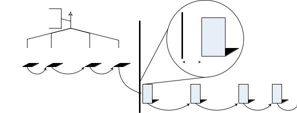
Wireless USB channel time is not synchronized to the underlying MAC Layer timing structure, so the host’s Wireless USB Channel time is continuous across any PHY channels where the host decides to locate the Wireless USB Channel. Since the time base is continuous, the host simply needs to notify the cluster members that MMCs will be available on a different PHY channel soon. The host accomplishes this by including a Channel Change announcement (see Section 7.5.3) in the MMCs which announces that a PHY channel change will occur at a specific Wireless USB channel time. The host must continue to obey the MMC transmission requirements, regardless of the PHY channel where it has located the Wireless USB channel. Figure 4-18 illustrates an example PHY channel change sequence.
54
Chapter 4 |
|
Data Flow Model |
Wireless Universal Serial Bus Specification, Revision 1.0 |
MMC
MMC |
|
MMC |
|
MMC |
|
MMC |
|
|
|
|
|
|
|
|
|
|
|
|
|
|
|
|
|
||||
|
|
|
|
|
|
|
|
|
|
|
|
|
|
|
|
|
|
|
|
|
|
|
|
|
|
|
|
MMC |
MMC |
MMC |
MMC |
Figure 4-18. Example Wireless USB Channel Change
The host must announce a PHY channel change in at least three (3) consecutive MMCs before the channel change event time. The host must specify a channel change event time that occurs after the transmission of the
last MMC in the original PHY channel and at least tBUSTURNINTERSLOTTIME (see Section 5.3) before the next MMC transmission in the destination PHY channel. If the host schedules protocol time slots between the two MMC
transmissions of different PHY channels, the channel switch time must be after the protocol time slots.
A Wireless USB device must simply move to the specified destination PHY channel at the specified Wireless USB channel time if it intends to remain a member of the host’s Wireless USB Cluster. If a device does not change channel with the host, then it will be detected as disconnected using the standard disconnect mechanism. If a device transitions out of the Sleep state and observes a Channel Change announcement, it should remain in the Active state until after the channel switch time has elapsed and it has completed a keep-alive notification on the new PHY channel. Note, Directed Beaconing Devices that have the Transmit Packet feature enabled, must disable this feature when transitioning to the new PHY channel. The intent of this requirement is that the device does not transmit the directed packet on the new PHY channel. The host may, at a later time re-enable the transmit packet feature on the device.
A host may have devices in the Sleep device state when it determines that is moving the Wireless USB cluster to a different PHY channel. When this is the case, the host may:
•Wait for all Sleeping devices to return to the Active device state before initiating a channel change, or
•Initiate and complete the channel change without waiting for devices in the Sleep state. Devices that miss the channel change due to being in the Sleep state simple need to locate their host and reconnect if they want to remain available for future data communications with the host.
The host may be able to accomplish the channel change without perturbing active data streams; however, this is beyond the scope of this specification. In general a host will use the Directed Packet Transmission and Reception feature with Directed Beaconing cluster members and GetStatus() and SetWUSBData() with Selfbeaconing cluster members to establish a neighbor-friendly reservation on the new PHY channel.
The host should change to a channel number that is supported by all current Wireless USB Cluster member devices.
55
Chapter 4 |
|
Data Flow Model |
Wireless Universal Serial Bus Specification, Revision 1.0 |
4.10.5Host Schedule Control
USB 2.0 (High-speed) requires that at least 20% of the available bus time be reserved for asynchronous data streams. Wireless USB preserves this allocation rule, but it allows a host to temporarily use/intrude on the asynchronous channel time in order to temporarily resolve reliability problems for periodic streams.
4.10.6 Dynamic Bandwidth Interface Control
Wireless USB defines an optional dynamic switching mechanism for interfaces containing isochronous endpoints. If an interface supports dynamic switching, the endpoints in the interface must support dynamically being reconfigured to a different bandwidth mode (represented by a different alternate setting). The process for performing a dynamic switch is described in detail in this section.. For example, the host may be able to switch an interface that supports dynamic switching to a lower bandwidth setting in a case where the PHY channel bandwidth has degraded significantly.
The process for performing a dynamic switch involves two steps. In the first part of the process the host sends a Set Interface DS (Dynamic Switch) control request to the device with an active interface that supports dynamic switching. The Set Interface DS request specifies a Wireless USB Channel time (switch time) for the dynamic switch to take place and an alternate setting that will be used after the switch. It is not possible to specify more than one switch time for different endpoints in an interface.
At the switch time an isochronous IN endpoint must start generating data in the format corresponding to the interface specified in the Set Interface DS request. When presentation times are applied, all data with presentation times after the switch time must use the format corresponding to the new alternate interface setting. The isochronous IN endpoint does not discard data that is currently buffered when it receives a Set Interface DS request. It continues to respond to IN requests following the characteristics of the current alternate interface. The device will be explicitly notified by the host when the host expects data transmitted over the air by the isochronous IN endpoint to correspond to the new alternate interface settings (maximum packet size, etc). This notification occurs during the second step in the dynamic switch process, which is described later in this section.
An isochronous OUT endpoint must handle data according to the appropriate format after the device has received a Dynamic Switch DS request. When the endpoint function processes data with presentation times after the specified switch time it must assume the data characteristics correspond to the alternate setting in the Dynamic Switch DS command. An isochronous OUT endpoint does not discard any data currently buffered when a Dynamic Switch DS request occurs. The isochronous OUT endpoint continues to process data according to the current interface settings as long as the presentation times associated with the data are before the switch time.
Note: There are a variety of implementations that a function endpoint could use to process data with presentation times before and after the switch time according to different formats. Some implementations may not rely on direct observation of presentation times.
In the second step of the dynamic switch process the host sends a Set Interface command to the device that previously received the Set Interface DS command. The Set Interface request must specify the same interface alternate setting that was specified in the Set Interface DS command (unless the host is selecting a different alternate setting with a traditional SetInterface() request). After the Set Interface request, over-the-air communication to and from all endpoints (of all types) in the specified interface must conform to the characteristics of the new alternate setting. After the Set Interface request is successfully completed the host will send all data to isochronous OUT endpoints in the switched interface using the over-the-air characteristics of the endpoint in the new alternate setting. After the Set Interface command the host expects an isochrones IN endpoint in the switched interface to respond with the over-the-air characteristics of the endpoint in the new alternate setting
There are several situations that can occur in the Dynamic Switch process. This section describes possible situations and host and device responsibilities in these cases.
•If a device that supports dynamic switching receives a Set Interface request without receiving a Set Interface DS request or receives a Set Interface request specifying a different alternate setting than the
56