

- •TABLE OF CONTENTS
- •1.1 Motivation
- •1.2 Design Goals
- •1.3 Objective of the Specification
- •1.4 Scope of the Document
- •1.5 USB Product Compliance
- •1.6 Document Organization
- •2.1 Terms
- •2.2 Conventions:
- •2.3 References
- •3.1 USB System Description
- •3.1.1 Topology
- •3.1.1.1 USB Host
- •3.1.1.2 Wireless USB Devices
- •3.2 Physical Interface
- •3.3 Power Management
- •3.4 Bus Protocol
- •3.5 Robustness
- •3.5.1 Error Handling
- •3.6 Security
- •3.7 System Configuration
- •3.7.1 Attachment of Wireless USB Devices
- •3.7.2 Removal of Wireless USB Devices
- •3.7.3 Bus Enumeration
- •3.8 Data Flow Types
- •3.9 Wireless USB Devices
- •3.9.1 Device Characterizations
- •3.9.2 Devices and MAC Layer
- •3.10 Wireless USB Host: Hardware and Software
- •4.1 Implementer Viewpoints
- •4.2 Communications Topology
- •4.2.1 Physical Topology
- •4.3 Wireless USB Communication Flows
- •4.3.1 Wireless USB Channel Time
- •4.3.2 MMC Transmission Accuracy
- •4.3.3 USB Time across Device Wire Adapters
- •4.3.5 Device Endpoints
- •4.3.6 Wireless USB Information Exchange Methods
- •4.3.7 Device Perspective
- •4.3.7.1 Self Beaconing Devices
- •4.3.7.2 Directed Beaconing Devices
- •4.3.7.3 Non Beaconing Devices
- •4.3.7.4 Selecting A Wireless USB Host
- •4.3.8 Host Perspective
- •4.3.8.1 MAC Layer Compliant Device
- •4.3.8.2 Wireless USB Host
- •4.3.8.3 Host System Management
- •4.3.8.5 Other Host Considerations
- •4.4 Data Transfers
- •4.4.1 Burst Mode Data Phase
- •4.5 Bulk Transfers
- •4.5.1 Bulk Transfer Packet Size and Signaling Rate Constraints
- •4.5.2 Bulk Transfer Channel Access Constraints
- •4.5.3 Bulk Transfer Data Sequences
- •4.6 Interrupt Transfers
- •4.6.1 Low Power Interrupt IN
- •4.6.2 Interrupt Transfer Packet Size and Signaling Rate Constraints
- •4.6.3 Interrupt Transfer Channel Access Constraints
- •4.6.4 Interrupt Transfer Data Sequences
- •4.7 Isochronous Transfers
- •4.7.1 Isochronous Transfer Packet Size and Signaling Rate Constraints
- •4.7.2 Isochronous Transfer Channel Access Constraints
- •4.7.3 Isochronous Transfer Data Sequences
- •4.7.4 Isochronous Endpoint Host System Admission Decisions
- •4.7.5 Isochronous Data Discards and Use of Isochronous Packet Discard IE
- •4.8 Control Transfers
- •4.8.1 Control Transfer Packet Size and Signaling Rate Constraints
- •4.8.2 Control Transfer Channel Access Constraints
- •4.8.3 Control Transfer Data Sequences
- •4.8.4 Data Loopback Commands
- •4.9 Device Notifications
- •4.10 Media Reliability Considerations
- •4.10.1 Transmit Power Control
- •4.10.2 Adjustments to Data Phase Packet Payload Sizes
- •4.10.3 Adjustments to Transmit Bit Rate
- •4.10.4 Changing PHY Channel
- •4.10.5 Host Schedule Control
- •4.10.6 Dynamic Bandwidth Interface Control
- •4.11 Special Considerations for Isochronous Transfers
- •4.11.1 Summary Of Key Features Of USB Wired Isochrony
- •4.11.1.1 Wireless Service Intervals
- •4.11.2 UWB Media Characteristics
- •4.11.2.1 Superframe Layout
- •4.11.2.2 Worst Case Superframe Layout – Service Interval Bounds.
- •4.11.2.3 Wireless Packet Error Rates
- •4.11.3 Wireless USB Isochronous Transfer Level Protocol
- •4.11.4 Wireless USB Isochronous IN Example
- •4.11.5 Wireless USB Isochronous OUT Example
- •4.11.6 Choosing an Isochronous IN or Isochronous OUT Endpoint Buffer Size
- •4.11.7 Isochronous OUT endpoint receiver implementation options
- •4.11.7.1 Presentation Time aware implementation
- •4.11.7.2 Presentation time aware implementation with “false” acknowledgement
- •4.11.7.3 Presentation time unaware implementations
- •4.11.8 Synchronization
- •4.11.8.1 Synchronizing a Stream Start Time
- •4.11.9 Error Handling Details
- •4.11.9.1 Reporting Data Discarded At the Transmitter
- •4.11.9.2 Discarding Data during A Burst
- •4.11.9.3 Application Handling of Discards
- •4.12 Device Reset
- •4.13 Connection Process
- •4.13.1 Reconnection Process
- •4.14 Disconnect
- •4.15 Security Mechanisms
- •4.15.1 Connection Lifetime
- •4.15.2 Host Security Considerations
- •4.15.2.1 CHID Selection
- •4.15.2.2 CDID Selection
- •4.16 Wireless USB Power Management
- •4.16.1 Device Power Management
- •4.16.1.1 Device Sleep
- •4.16.1.2 Device Wakeup
- •4.16.2 Host Power Management
- •4.16.2.1 Channel Stop
- •4.16.2.2 Remote Wakeup
- •4.16.2.3 Channel Start
- •4.17 Dual Role Devices (DRD)
- •4.17.2 Pairing P2P-DRD to establish reverse link
- •5.1 Packet Formats
- •5.2 Wireless USB Transaction Groups
- •5.2.1 Wireless USB Channel Time Allocation Information Elements
- •5.3 Transaction Group Timing Constraints
- •5.3.1 Streaming-Mode Inter-packet Constraints for the PHY
- •5.3.2 Protocol Synchronization
- •5.4 Data Burst Synchronization and Retry
- •5.5 Wireless USB Transactions
- •5.5.1 Isochronous Transactions
- •5.5.2 Control Transfers
- •5.5.3 Device Notifications
- •5.5.4 Flow Control
- •6.1 Introduction
- •6.1.1 Goal of USB Security
- •6.1.2 Security and USB
- •6.2 Overview
- •6.2.1 Base of Trust
- •6.2.2 Preserve the Nature of the USB Device Model
- •6.2.3 Implementation of Security Extensions
- •6.2.4 Encryption Methods
- •6.2.5 Message Format
- •6.2.6 Encryption Keys
- •6.2.6.1 Master Keys
- •6.2.6.2 Session Keys
- •6.2.7 Correct key determination
- •6.2.8 Replay Prevention
- •6.2.9 Secure Packet Reception
- •6.2.10 General Connection Model
- •6.2.10.1 Connection Context
- •6.2.10.2 Connection Lifetime
- •6.2.10.3 New Connection
- •6.2.10.4 Connection
- •6.2.10.5 Reconnection
- •6.2.10.6 Revocation
- •6.2.10.8 Diagnostic Support
- •6.2.10.9 Mutual Authentication
- •6.2.11 Key Management
- •6.2.11.1 PTK Management
- •6.2.11.2 GTK Management
- •6.3 Association and Authentication
- •6.3.1 Connection and Reconnection Requests
- •6.3.2 Authentication
- •6.3.2.1 Authentication Related Device Capabilities
- •6.3.2.2 Ceremonies
- •6.4.1 CCM nonce Construction
- •6.4.2 l(m) and l(a) Calculation
- •6.4.3 Counter-mode Bx Blocks
- •6.4.4 Encryption Ax Blocks
- •6.5.1 Key Derivation
- •6.5.2 Out-of-band MIC Generation
- •6.5.3 Example Random Number Generation
- •7.1 Wireless USB Device States
- •7.1.1 UnConnected
- •7.1.2 UnAuthenticated
- •7.1.3 Authenticated
- •7.1.4 Reconnecting
- •7.2 Generic Wireless USB Device Operations
- •7.3 Standard Wireless USB Device Requests
- •7.3.1 Wireless USB Extensions to Standard Requests
- •7.3.1.1 Clear Feature
- •7.3.1.2 Get Status
- •7.3.1.3 Set Address
- •7.3.1.4 Set Feature
- •7.3.1.5 Set Interface DS
- •7.3.1.6 Set WUSB Data
- •7.3.1.7 Data Loopback Write
- •7.3.1.8 DATA Loopback Read
- •7.3.2 Security-related Requests
- •7.3.2.1 Get Security Descriptor
- •7.3.2.2 Set Encryption
- •7.3.2.3 Get Encryption
- •7.3.2.4 Key Management
- •7.3.2.6 Set Security Data
- •7.3.2.7 Get Security Data
- •7.4 Standard Wireless USB Descriptors
- •7.4.1 Device Level Descriptors
- •7.4.1.1 Wireless USB Device Capabilities – UWB
- •7.4.2 Configuration
- •7.4.3 Endpoint
- •7.4.4 Wireless USB Endpoint Companion
- •7.4.5 Security-Related Descriptors
- •7.4.5.1 Security Descriptor
- •7.4.5.2 Key Descriptor
- •7.5 Wireless USB Channel Information Elements
- •7.5.1 Wireless USB Connect Acknowledge IE
- •7.5.2 Wireless USB Host Information IE
- •7.5.3 Wireless USB Channel Change Announcement IE
- •7.5.4 Wireless USB Device Disconnect IE
- •7.5.5 Wireless USB Host Disconnect IE
- •7.5.6 Wireless USB Release Channel IE
- •7.5.7 Wireless USB Work IE
- •7.5.8 Wireless USB Channel Stop IE
- •7.5.9 Wireless USB Device Keepalive IE
- •7.5.10 Wireless USB Isochronous Packet Discard IE
- •7.5.11 Wireless USB Reset Device IE
- •7.5.12 Wireless USB Transmit Packet Adjustment IE
- •7.6 Device Notifications
- •7.6.1 Device Connect (DN_Connect)
- •7.6.1.1 Connect Request
- •7.6.1.2 Reconnect Request
- •7.6.2 Device Disconnect (DN_Disconnect)
- •7.6.3 Device Endpoints Ready (DN_EPRdy)
- •7.6.4 Device MAS Availability Changed (DN_MASAvailChanged)
- •7.6.5 Device Sleep (DN_Sleep)
- •7.6.6 Remote Wakeup (DN_RemoteWakeup)
- •7.6.7 Device Alive (DN_Alive)
- •8.1 Operational Model
- •8.1.1 Functional Characteristics
- •8.1.2 Data Transfer Interface
- •8.1.3 Remote Pipe
- •8.1.4 Wire Adapter Functional Blocks
- •8.1.5 Downstream Port(s)
- •8.1.6 Upstream Port
- •8.1.7 Downstream Host Controller
- •8.1.8 Upstream Endpoint Controller
- •8.1.9 Remote Pipe Controller
- •8.1.9.1 RPipe Descriptor
- •8.1.9.2 Bulk OUT Overview
- •8.1.9.3 Bulk IN Overview
- •8.1.9.4 Control Transfer Overview
- •8.1.9.5 Interrupt Transfer Overview
- •8.1.9.6 Isochronous Transfer Overview
- •8.1.10 Suspend and Resume
- •8.1.10.1 DWA Suspend and Resume
- •8.1.10.2 HWA Suspend and Resume
- •8.1.11 Reset Behavior
- •8.1.12 Device Control
- •8.1.13 Buffer Configuration
- •8.2 Descriptors
- •8.3 Requests
- •8.3.1 Wire Adapter Class-Specific Requests
- •8.3.1.1 Abort RPipe
- •8.3.1.2 Clear RPipe Feature
- •8.3.1.3 Clear Wire Adapter Feature
- •8.3.1.4 Get RPipe Descriptor
- •8.3.1.5 Get RPipe Status
- •8.3.1.6 Get Wire Adapter Status
- •8.3.1.7 Set RPipe Descriptor
- •8.3.1.8 Set RPipe Feature
- •8.3.1.9 Set Wire Adapter Feature
- •8.3.1.10 Reset RPipe
- •8.3.2 Notification Information
- •8.3.3 Transfer Requests
- •8.3.3.1 Control Transfers
- •8.3.3.2 Bulk and Interrupt Transfers
- •8.3.3.3 Transfer Completion Notification
- •8.3.3.4 Transfer Result
- •8.3.3.5 Abort Transfer
- •8.4 DWA Interfaces, Descriptors and Control
- •8.4.1 DWA Isochronous Streaming Interface
- •8.4.2 DWA Isochronous Streaming Overview
- •8.4.3 DWA Descriptors
- •8.4.3.1 Device Descriptor
- •8.4.3.2 Binary Device Object (BOS) Descriptor
- •8.4.3.3 Configuration Descriptor
- •8.4.3.4 Security Descriptors
- •8.4.3.5 Interface Association Descriptor
- •8.4.3.6 Data Transfer Interface Descriptor
- •8.4.3.7 Wire Adapter Class Descriptor
- •8.4.3.8 Notification Endpoint Descriptor
- •8.4.3.9 Notification Endpoint Companion Descriptor
- •8.4.3.10 Data Transfer Write Endpoint Descriptor
- •8.4.3.11 Data Transfer Write Endpoint Companion Descriptor
- •8.4.3.12 Data Transfer Read Endpoint Descriptor
- •8.4.3.13 Data Transfer Read Endpoint Companion Descriptor
- •8.4.3.14 Isochronous Streaming Interface Descriptor
- •8.4.3.15 Isochronous Streaming OUT Endpoint Descriptor
- •8.4.3.16 Isochronous Streaming OUT Endpoint Companion Descriptor
- •8.4.3.17 Isochronous Streaming IN Endpoint Descriptor
- •8.4.3.18 Isochronous Streaming IN Endpoint Companion Descriptor
- •8.4.3.19 Wire Adapter RPipe Descriptor
- •8.4.4 DWA Specific Requests
- •8.4.4.1 Clear Port Feature
- •8.4.4.2 Get Port Status
- •8.4.4.3 Set Isochronous Endpoint Attributes
- •8.4.4.4 Set Port Feature
- •8.4.5 DWA Notification Information
- •8.4.5.1 Remote Wake
- •8.4.5.2 Port Status Change
- •8.4.6 DWA Isochronous Transfers
- •8.4.6.1 DWA Isochronous OUT Responsibilities
- •8.4.6.2 DWA Isochronous IN Responsibilities
- •8.5 HWA Interfaces, Descriptors and Control
- •8.5.1 HWA Isochronous Streaming Overview
- •8.5.2 HWA Descriptors
- •8.5.2.1 Device Descriptor
- •8.5.2.2 Device_Qualifier Descriptor
- •8.5.2.3 Configuration Descriptor
- •8.5.2.4 Other_Speed_Configuration Descriptor
- •8.5.2.5 Security Descriptors
- •8.5.2.6 Data Transfer Interface Descriptor
- •8.5.2.7 Wire Adapter Class Descriptor
- •8.5.2.8 Notification Endpoint Descriptor
- •8.5.2.9 Data Transfer Write Endpoint Descriptor
- •8.5.2.10 Data Transfer Read Endpoint Descriptor
- •8.5.2.11 Wire Adapter RPipe Descriptor
- •8.5.3 HWA Specific Requests
- •8.5.3.2 Get BPST Adjustment
- •8.5.3.3 Get BPST Time
- •8.5.3.4 Get WUSB Time
- •8.5.3.5 Remove MMC IE
- •8.5.3.6 Set Device Encryption
- •8.5.3.7 Set Device Info
- •8.5.3.8 Set Device Key
- •8.5.3.9 Set Group Key
- •8.5.3.10 Set Num DNTS Slots
- •8.5.3.11 Set WUSB Cluster ID
- •8.5.3.12 Set WUSB MAS
- •8.5.3.13 Set WUSB Stream Index
- •8.5.3.14 WUSB Channel Stop
- •8.5.4 HWA Notification Information
- •8.5.4.1 BPST Adjustment Change
- •8.5.4.2 DN Received Notification
- •8.5.5 HWA Isochronous Transfers
- •8.5.5.1 HWA Isochronous OUT Responsibilities
- •8.5.5.2 HWA Isochronous IN Responsibilities
- •8.5.5.3 HWA Isochronous Transfer Completion
- •8.6 Radio Control Interface
- •8.6.1 Radio Control Descriptors
- •8.6.1.1 Radio Control Interface Descriptor
- •8.6.1.2 Radio Control Interface Class Descriptor
- •8.6.1.3 Radio Control Interrupt Endpoint Descriptor
- •8.6.2 Radio Control Command
- •8.6.2.1 Channel Change
- •8.6.2.2 Device Address Management
- •8.6.2.4 Reset
- •8.6.2.5 Scan
- •8.6.2.6 Set Beacon Filter
- •8.6.2.9 Set Notification Filter
- •8.6.2.10 Set TX Power
- •8.6.2.11 Sleep
- •8.6.2.12 Start Beaconing
- •8.6.2.13 Stop Beaconing
- •8.6.3 Radio Control Notifications
- •8.6.3.1 Application-specific Probe IE Received Notification
- •8.6.3.2 Beacon Received Notification
- •8.6.3.3 Beacon Size Notification
- •8.6.3.4 BPOIE Change Notification
- •8.6.3.5 BP Slot Change Notification
- •8.6.3.6 BP Switch IE Received Notification
- •8.6.3.7 Device Address Conflict Notification
- •8.6.3.8 DRP Availability Changed Notification
- •8.6.3.9 DRP Notification
- •A.1 Key Derivation
- •A.2 Handshake MIC calculation
- •A.3 Secure MMC (EO = payload length)
- •A.4 Data IN from device (EO = 2)
- •B.1 Descriptors for DWA
- •B.2 Descriptors for HWA
Chapter 2 |
|
Terms, Conventions and References |
Wireless Universal Serial Bus Specification, Revision 1.0 |
2.2Conventions:
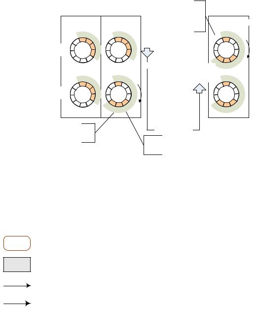
Figure 2-1 illustrates the convention for figures in Section 5.4 for illustrating the burst data phase protocol (explained later in this specification).
Figure 2-1. Data Burst Transaction Convention
There may be more than one transaction per illustration/example. For each transaction, there is an initial condition of what is called the Transmit and Receive windows, illustrated as a number wheel, with shading in the spoke region indicating the current window. The numbers on the wheel represent the sequence numbers associated with the window locations. Shading on the outside of the wheel indicates the current distance between the current extremes of the sequence numbers in the current window (called sequence distance).
Figure 2-2 illustrates the conventions used in for the transaction diagrams in Chapter 5.
Figure 2-2. Transaction Diagram Conventions.
9
Chapter 2 |
|
|
|
|
|
|
|
Terms, Conventions and References |
Wireless Universal Serial Bus Specification, Revision 1.0 |
||||||
|
|
|
|
|
|
|
|
|
Light/Yellow shading/highlights in tables is used to illustrate standard/required portions |
|
|
|
|
|
|
|
of dynamic structures. If there is no highlighting, then the entire table contents are |
|
|
|
|
|
|
|
required. |
|
|
|
|
|
|
|
If a table has only white and shaded portions, the shaded portion(s) indicate valid |
|
|
|
|
|
|
|
portion and the white indicates invalid portion(s). If there is no shading, then the entire |
|
|
|
|
|
|
|
|
|
Invalid Value |
|
|||
|
table contents are valid values. |
|
|
|
|
||
|
|
|
|
|
Valid Value |
|
|
|
|
|
|
|
|
|
|
•Variable, field names and Device Notifications are italicized.
•Device states are bold.
•Numbers without a base indicator are in decimal. Non-decimal numbers have a base indicator appended to the value. The base indicators used in this specification are: (H - Hexi-decimal and B - Bindary). Note that some examples use a (0x) prefix base indicator for Hexi-decimal values.
2.3References
[1]Universal Serial Bus Specification (Revision 2.0). April 27, 2000. Universal Serial Bus Implementers Forum (USBIF). Including all published Errata.
[2]Interface Association Descriptor Engineering Change Notice (Revision 1.0). July 23, 2003. This is an Engineering Change Notice to Universal Serial Bus Specification (Revision 2.0)
[3]Distributed Medium Access Control (MAC) Specification for Wireless Networks (Revision 1.0). 2005. WiMedia Alliance. This is also currently defined as the MBOA MAC.
[4]Multiband OFDM Physical Layer Specification. (Revision 1.) January 14, 2005. WiMedia Alliance. This is also currently known has the MBOA PHY specification.
[5]NIST FIPS Pub 197: Advanced Encryption Standard (AES), Federal Information Processing Standards Publication 197, US Department of Commerce/N.I.S.T., November 16, 2001.
[6]NIST Special Publication 800-38C, Recommendation for Block Cipher Modes of Operation: The CCM Mode for Authentication and Confidentiality.
[7]WiMedia MAC Convergence Architecture Specification (Revsion 1.0). 2005. WiMedia Alliance.
10