

Chapter 4 |
|
Data Flow Model |
Wireless Universal Serial Bus Specification, Revision 1.0 |
Figure 4-24. Typical Reservation for Wireless USB Host
In Figure 4-24 the Wireless USB host has reserved roughly half of time available for reservations in the superframe. The largest gap between Wireless USB host time slots occurs between the reservations before and after the beacon period. The gap is 6.144 milliseconds. The gaps between the other Wireless USB host time slots are 2.048 milliseconds. In cases where the Wireless USB host reserves a smaller percentage of the superframe the largest gap approaches 8.192 milliseconds for the time slots before and after the beacon. The largest gap between other Wireless USB host time slots (not across the beacon reservation) approaches 4.096 milliseconds.
4.11.2.3Wireless Packet Error Rates
Error rates for wireless USB transfers can be much higher than wired USB error rates. Typical wireless average bit error rates can be as high as 10-4 with short term spikes to much higher error rates. For 1000 byte packets, this translate into an average packet error rate (PER) of 10%.
Wired USB bit error rates are required to be 10-9 or better. The wired USB protocol can ignore the possibility of errors (no handshaking to indicate if data was successfully received in the wired USB isochronous protocol) and still provide PER of 10-6 or better for 1000 byte packets. If the wireless USB isochronous protocol were to continue to not use handshaking, it would have to send each packet on the order of 6 times to guarantee matching wired reliability. From an efficiency standpoint for the wireless USB bus, this approach is not feasible. Therefore, the wireless USB isochronous protocol uses handshaking.
4.11.3Wireless USB Isochronous Transfer Level Protocol
At the transaction level, the wireless USB isochronous protocol is almost identical to the wireless USB bulk protocol. The protocol is defined in the protocol chapter. Wireless USB defines mechanisms for isochronous function endpoints to allow error reporting when data is discarded and to allow backwards compatibility with some existing class drivers and applications that support wired USB isochronous endpoints.
4.11.4 Wireless USB Isochronous IN Example
This section walks through a simple high level example to illustrate the basic steps that occur in the operation of a wireless USB isochronous IN endpoint. When a device with an isochronous IN endpoint exchanges configuration information with the wireless USB host, it reports the amount of buffering that it has for use with each isochronous IN endpoint. The buffering amount is reported in the wMaxStreamDelay field in the Endpoint Companion descriptor, see Section 7.4.4. As shown in Figure 4-25, the host must set aside a larger amount of buffering for working with the endpoint. The buffer set aside by the host must be at least one max packet size larger than the buffer reported by the device for the isochronous IN endpoint. Note: Wireless USB Host refers generically to the system containing the wireless USB host controller.
61
Chapter 4 |
|
Data Flow Model |
Wireless Universal Serial Bus Specification, Revision 1.0 |
Figure 4-25. Configuring Wireless USB Isochronous IN Endpoint
The isochronous IN endpoint in this example produces an average of 30 1024 byte packets every 65.536 milliseconds. The device contains enough buffering to store 8 of these packets. The endpoint descriptor requests a service interval of 4.096 milliseconds, a maximum packet size of 1024 bytes, a maximum burst size of 2, and a maximum stream delay of 16.384 milliseconds. Note that a 4.096 millisecond service interval provides service only 15 times every 65.536 milliseconds due to the reserved period for beacons.
Figure 4-26. Isochronous IN Endpoint and Host Buffering
Figure 4-26 shows the size of the isochronous IN endpoint and corresponding host buffers. The buffer positions are indexed for reference throughout the example. The example isochronous IN endpoint produces data continuously when powered.
When the device buffer fills the oldest data in the buffer is thrown away to make room for the new data. When the first request for data from the wireless host occurs, the endpoint buffer is full.
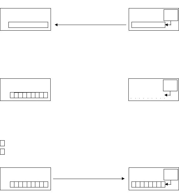
Figure 4-27. Initial Data Request From Isochronous IN Endpoint
Figure 4-27 shows the initial request for data. When the first request for data comes from the host, the device responds with data from its buffer. There are several ways that the isochronous endpoint could handle the initial response for data. In Figure 4-28, the isochronous IN endpoint sends the oldest data in its buffer in response to the first request for data when the stream starts.
62
Chapter 4 |
|
Data Flow Model |
Wireless Universal Serial Bus Specification, Revision 1.0 |
Figure 4-28. Isochronous IN Endpoint Sends Oldest Data In Buffer In Response To Initial Request
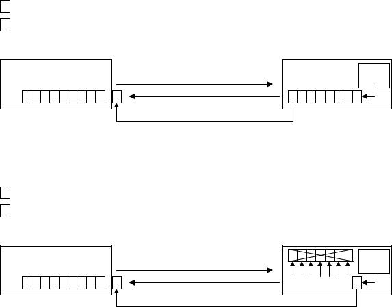
Responding with the oldest data in the buffer leaves the function endpoint susceptible to errors early in the stream. If the initial packet is successfully transferred – but several errors occur shortly thereafter, the function endpoint may have to throw away data. An alternate approach is shown in Figure 4-29.
Figure 4-29. Isochronous IN Endpoint Sends Newest Data In Response To First Request And Clears Buffers
In this case the function endpoint sends the newest data in its buffer in response to the first request and then discards all other data. Subsequent data is stored normally. The function endpoint may now buffer up to 8 packets before discarding data – even during the initial startup of the stream.
Note: There are a variety of options for when an isochronous IN endpoint starts storing data in its buffer and how it responds to the first isochronous IN request. A device designer should keep in mind that some options will provide better error tolerance as the stream starts than others.
The host will continue to request data. In this implementation, when the host has received enough data to fill its initial buffer – the application will begin to consume data. Figure 4-30 shows the state of the system when data consumption begins.
63

Chapter 4 |
|
Data Flow Model |
Wireless Universal Serial Bus Specification, Revision 1.0 |
Figure 4-30. Data Consumption Begins
The host buffer fills and the oldest data in the buffer is sent to the application. Each data packet sent by the isochronous IN device contains header information that indicates the Wireless USB Channel time when the data was produced. These presentation times are used by the host to apply the data to specific locations in application buffers.
Unless there have been significant errors during the start up of the stream, the device buffer will be close to empty. A delay of approximately 16 milliseconds has been added to the system by the buffering and stream startup conditions. This delay provides tolerance to short term errors and glitches in the stream as operation continues. If the device had desired greater tolerance to short term error bursts and glitches it could use additional buffering. The amount of buffering to use is a device decision. Deciding on the amount of buffering is a tradeoff between cost, error tolerance, and the amount of acceptable delay/latency in the stream. The tradeoff is discussed in more detail in Section 4.11.6.
During normal operation the isochronous IN endpoint buffer will stay relatively empty and the host buffer will stay relatively full. If there is a prolonged period where the error rate is high the endpoint buffer will begin to fill and the host buffer will begin to empty. As long as the error rate decreases again before the endpoint buffer overflows, the system will recover because the host allocates guaranteed time for retries each service interval as part of the bandwidth reservation for the endpoint. However, if the errors continue the endpoint buffer will eventually overflow and the host will be unable to provide data to the application.
Figure 4-31. Data Must Be Discarded By Isochronous IN Function Endpoint
Figure 4-31 shows the case where the error rate has been significant for a prolonged period. The endpoint produces its next data packet but has no place to store it. At this point the isochronous IN endpoint must discard its oldest data to store the new data. This is the only case where data is discarded with an isochronous IN stream. The device will continue to try to send data until it is forced to discard data when its buffer overflows. Section 4.11.9 examines error handling in more detail. When an isochronous IN endpoint discards data it must re-use the burst sequence number associated with the discarded packet. The host processes data packets based on their presentation times and will still place data in the correct locations in application buffers. There are methods for communicating the amount of information that has been discarded and options for attempting to prevent a buffer overflow from occurring.
64