

Chapter 4 |
|
Data Flow Model |
Wireless Universal Serial Bus Specification, Revision 1.0 |
•Any control request other than a Data Loopback Read or Data Loopback Write occurs. The device is not required to continue to store loopback data.
•A Data Loopback Read Request occurs. If the device has stored loopback data it is required to return that data (up to the requested length) in a single packet in the data stage of the Data Loopback Read request. If the requested length is longer than the length of the stored data, device behavior is undefined. The device must use the specified power level and data rate in the data stage of the request. After a Data Loopback Read request occurs, the device must continue to store the loopback data until one of the events described in the preceding bulleted items occurs.
4.9Device Notifications
Device Notifications are a standard method for a device to communicate asynchronous, device and Bus-level event information to the host. This communication method is a bus-level feature that does not map to the pipe model defined for the standard transfer types. Device Notifications are always initiated by a device and the flow of data information is always device to host. Each packet transmitted is called a Device Notification or simply Notification.
Notifications are message-oriented data communications that have a specific data format structure as defined in Section 7.6 and a specific media access mechanism as defined in Section 5.2.1.3 which describes Device Notification Time Slots (DNTS). These data communications do not use Wireless USB data transactions as defined in Section 5.3 to accomplish data transfers. The maximum allowable data payload for a Device Notification message is 32 bytes and the messages must always be transmitted at the PHY base signaling rate.
Device Notification time slots are scheduled by the host on an “as-needed” basis. The amount of channel time scheduled by the host depends on the service intervals of the pending events (flow control, keep alives, etc.) and implementation specific policies of the host. A host may schedule a maximum of one device notification time slot per MMC.
4.10Media Reliability Considerations
Wireless is an unreliable media, as compared to most non-wireless technologies (i.e. copper, optical, etc). There are many different forms of interference that contribute to unreliability and a commensurate quantity of interference mitigation techniques. In Wireless USB, interference mitigation is managed by the host of the Wireless USB Channel which has the bits of information and set of characteristics to control listed below.
Information
Host-centric information |
The host can maintain statistical information on every device (PER, |
|
etc.), it also has physical information about what its view of the MAC |
|
Layer channel is like (LQI, etc.). |
Device-centric information |
The host can query the device for its view of the MAC Layer channel. |
|
The information returned includes: LQI, etc. |
Controls |
|
Transmit Power Control |
(TPC). Wireless USB offers manipulation of transmit power levels via |
|
transaction level control attributes and device-level management |
|
commands. See Section 4.10.1 for details. |
Transmit Bit Rate Control |
The transmit bit rate can be adjusted on a per-transaction basis. |
50
Chapter 4 |
|
Data Flow Model |
Wireless Universal Serial Bus Specification, Revision 1.0 |
Controls (cont.)
Data payload Size Control |
The nominal size of the data payload of transmitted packets is |
|
established by the wMaxPacketSize of the function endpoint. |
|
A commonly defined wireless tool for mitigating some forms of |
|
interference is the ability to change the size of data packets, so that they |
|
are statistically less likely to be corrupted during transmission. See |
|
Section 4.10.2 for details. This is an optional feature for devices and |
|
hosts. |
Transfer Burst Size |
A device exports a maximum level of bursting capability, and the host |
|
(depending on transfer type) can choose to utilize the bursting |
|
capability up to the level required for fair and efficient service for the |
|
devices connected to the Wireless USB Channel. |
PHY Channel Change |
A host can choose to move the Wireless USB channel and associated |
|
cluster to an alternative PHY channel. See Section 4.10.4 for details. |
Host Schedule Control |
The host may temporarily use time allotted for asynchronous |
|
(bulk/control) transactions to provide additional retries for streams that |
|
are experiencing significant error rates. |
Dynamic Bandwidth |
Some interfaces containing isochronous endpoints may support being |
Interface Control |
dynamically switched to other bandwidth modes. The host may be able |
|
to switch an interface to address a change in available bandwidth. |
The following sections provide overview descriptions of the controls that are available to a host controller, the application of these controls is a host implementation issue and beyond the scope of this specification.
USB 2.0 specifies that a transaction for a non-isochronous endpoint will be attempted at most 3 times before the associated pipe is put into a Stalled state (isochronous gets one try). Wireless USB provides a host a much larger number of attempts in order to allow a reasonable number of transaction opportunities over which it can employ the controls described below to optimize the Wireless USB channel for data communications between the host and a Function Endpoint. Wireless USB requires a host to try a transaction at least seven (7) times before stalling a non-isochronous pipe. Retries are applied at the transaction level, not the data packet level. For example, if any data packet of a burst succeeds (i.e. the data stream advances), then the host’s pipe retry counter should be reset to zero. Isochronous pipes don’t stall and have specifically defined mechanisms for advancing the data stream when data cannot make it from source to sink and data expires see Section 4.11. Note that lowpower Interrupt IN endpoints must be managed with a different retry policy. These types of function endpoints are explicitly allowed to not respond if they do not have data. Therefore, there is no practical maximum retry count that is applicable. However, it is still necessary to determine whether the function or function endpoint has failed.
4.10.1Transmit Power Control
Wireless USB devices report the TPC levels and adjustments they support (see Section 7.4.1.1). A host may set the TPC level(s) of a device. The power levels for beacons/directed transmissions and notifications for the device are managed using the device-level set WUSB data request (see Section 7.3.1 for details). The host can query the current device level transmit power control settings by issuing a GetStatus() request on the Default Control Pipe for the device-level features. A host specifies the power level to be used by the device for data and handshake packets transmitted by the device. Note, the device resets these parameters to their default values (i.e. highest power setting) whenever the device returns to the UnConnected device state.
The transmit power control settings for the device are only valid for data communications over the associated Wireless USB channel. For example if a device implementation supports multiple protocols (For example, Wireless IP and Wireless USB), the transmit power settings only affect data communications for the Wireless
51

Chapter 4 |
|
Data Flow Model |
Wireless Universal Serial Bus Specification, Revision 1.0 |
USB Channel. If a device is capable of simultaneous operation on more than one Wireless USB channel, the transmit power adjustments only apply to the channel in which the adjustment is made.
The host can make power transmit level adjustments to device beacons/directed transmission and to Device Notifications or for individual protocol time slots at any time. The device is required to activate the change in transmit power for the next packet transmission from the device (after the new power setting has been received from the host). All devices are required to support transmit power control. The power control settings allow 8 power levels to be specified. A device reports the size of the steps between power levels, and number of power levels that are supported for operation on TFI and FFI channels. This version of the specification requires devices to support a power level step size of 2 dB and specifies accuracy requirements on supported power levels that allow both baseband and RF implementations of transmit power level control. There are two parts to the accuracy requirements:
•Absolute allowed ranges for each power level.
•Additional constraints that guarantee monotonically decreasing power levels for each increasing power control setting.
Table 4-4 shows the nominal power levels with a 2 dB step for each Wireless USB Power Control Setting and the absolute accuracy requirements for each level. The shaded power levels in the table must be supported by all devices.
Table 4-4 Nominal Transmit Power Level Values and Accuracy Requirements for Each Level
Power |
TFI Channel Power Level |
|
FFI Channel Power Level |
||||
Control |
|
|
|
|
|
|
|
Setting |
Nominal values |
|
Accuracy requirement |
|
Nominal values |
|
Accuracy requirement |
|
|
|
|
|
|
|
|
0 |
TFI_BASE |
|
TFI_BASE |
|
FFI_BASE |
|
FFI_BASE |
1 |
TFI_BASE – 2 dB |
|
TFI_BASE – (1 to 3) dB |
|
FFI_BASE – 2 dB |
|
FFI_BASE – (1 to 3) dB |
2 |
TFI_BASE – 4 dB |
|
TFI_BASE – (3 to 5) dB |
|
FFI_BASE – 4 dB |
|
FFI_BASE – (3 to 5) dB |
3 |
TFI_BASE – 6 dB |
|
TFI_BASE – (4.8 to 7.2) dB |
|
FFI_BASE – 6 dB |
|
FFI_BASE – (4.8 to 7.2) dB |
4 |
TFI_BASE – 8 dB |
|
TFI_BASE – (6.4 to 9.6) dB |
|
FFI_BASE – 8 dB |
|
FFI_BASE – (6.4 to 9.6) dB |
5 |
TFI_BASE – 10 dB |
|
TFI_BASE – (8 to 12) dB |
|
FFI_BASE – 10 dB |
|
FFI_BASE – (8 to 12) dB |
6 |
TFI_BASE – 12 dB |
|
TFI_BASE – (9.6 to 14.4) dB |
|
FFI_BASE – 12 dB |
|
FFI_BASE – (9.6 to 14.4) dB |
7 |
TFI_BASE _ 14 dB |
|
TFI_BASE – (11.2 to 16.8) dB |
|
FFI_BASE – 14 dB |
|
FFI_BASE – (11.2 to 16.8) dB |
|
|
|
|
|
|
|
|
The absolute accuracy requirements allow the power levels to overlap.
As mentioned above, there are requirements to ensure that the absolute power levels decrease when power control settings are increased. These requirements constrain the amount that the absolute power level can change for a change of N Power Control Settings. Table 4-5 shows the required range of the power change for each possible size of change for the Power Control Setting.
Table 4-5 Required Range Of Power Level Change For Changes In Power Control Setting
Change In Power Control Setting Value |
Required Change In Absolute Power Level |
|
|
|
|
1 |
1 |
to 3 dB |
2 |
3 |
to 5 dB |
|
|
|
3 |
4.8 |
to 7.2 dB |
|
|
|
4 |
6.4 |
to 9.6 dB |
5 |
8 |
to 12 dB |
|
|
|
6 |
9.6 |
to 14.4 dB |
|
|
|
7 |
11.2 |
to 16.8 dB |
52
Chapter 4 |
|
Data Flow Model |
Wireless Universal Serial Bus Specification, Revision 1.0 |
For example, any change of 2 power control setting value must correspond to a power level change of at least 3 dB and no more than 5 dB. Therefore, if the absolute power level for setting 4 was TFI_BASE – 8 dB then the absolute power levels for settings 2 and 6 would have to be within the ranges TFI_BASE – (3 to 5) dB and TFI_BASE – (11 to 13) dB respectively.
If instead the absolute power level for setting 4 was TFI_BASE – 6.4 dB then the absolute power levels for settings 2 and 6 would have to be within the ranges TFI_BASE – (3 to 3.4) dB and TFI_BASE – (9.6 to 11.4) dB respectively. These values may be derived as follows: A change from setting 0 to setting 2 must be at least 3 dB. Therefore setting 2 can not be less than 3 dB below the TFI_BASE (regardless of the value for setting 4). A change of 6 settings must be at least 9.6 dB. Therefore setting 6 can not be less than 9.6 DB below TFI_BASE (regardless of the value for setting 4).
4.10.2 Adjustments to Data Phase Packet Payload Sizes
Large data packets are more efficient for moving data except when interference causes the packet error rate to increase and retries dominate the transaction traffic on the channel. Packets with larger payloads have a statistical higher probability of encountering an uncorrectable error. Therefore, under certain circumstances, throughput efficiency can be increased by decreasing the size of transmitted data packets.
A host can adjust the payload sizes of data phase data packets as one method of managing the packet error rate on data streams. The effective data stream is illustrated in Figure 4-17.
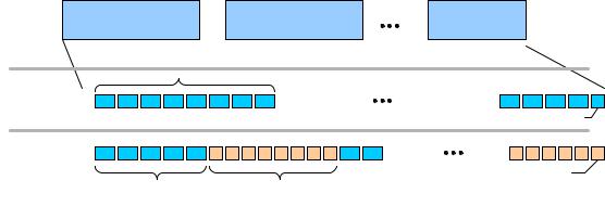
Figure 4-17. Transfer to Transmitted Packet Mapping for USB 2.0 and Wireless USB
USB 2.0 data communications require (for Bulk, Control and Interrupt transfer types) endpoints to always transmit data payloads with a data field less than or equal to the function endpoint’s declared wMaxPacketSize). When a transfer request has more data than can fit in one maximum-sized payload, all data payloads are required to be maximum size except for the last payload, which will contain the remaining data. A transmitter may complete a transfer by moving exactly the data expected, or more generically, the transmitter may delineate the data stream by transmitting a short packet (i.e. less than wMaxPacketSize bytes in a data payload). Note that zero bytes in the data packet payload is still considered a short packet. Short packet semantics must be preserved for Wireless USB Bulk, Control and Interrupt function endpoints. Figure 4-17 illustrates this behavior in the top and middle rows, where the top row is a buffer stream (which may be one or more buffers) that represents a transfer of some application-specific unit of data. The middle row illustrates, the ‘bus’ view of the data payloads, each of wMaxPacketSize. ‘R’ represents the residual or remaining data which is less than wMaxPacketSize. The bottom row of Figure 4-17 illustrates the ‘bus’ view of data payloads where, under control of the host, the payload sizes of data packets in the data stream may be wMaxPacketSize intermixed with adjusted payload sizes (aMaxPacketSize). The limits about how and when a host is allowed to adjust payload sizes in a data stream are described below. The mix is controlled and managed by the host’s implementation policy.
To preserve short packet semantics and support adjustments to data payload sizes less than the reported wMaxPacketSize, the short packet occurrences in the data stream must always be explicitly marked by the transmitter (regardless of whether the host or device supports data packet size adjustments). The bmStatus.Flags.Last Packet Flag field in the Wireless USB data header (see Section 5.1) is used to mark the
53