- •TABLE OF CONTENTS
- •1.1 Motivation
- •1.2 Design Goals
- •1.3 Objective of the Specification
- •1.4 Scope of the Document
- •1.5 USB Product Compliance
- •1.6 Document Organization
- •2.1 Terms
- •2.2 Conventions:
- •2.3 References
- •3.1 USB System Description
- •3.1.1 Topology
- •3.1.1.1 USB Host
- •3.1.1.2 Wireless USB Devices
- •3.2 Physical Interface
- •3.3 Power Management
- •3.4 Bus Protocol
- •3.5 Robustness
- •3.5.1 Error Handling
- •3.6 Security
- •3.7 System Configuration
- •3.7.1 Attachment of Wireless USB Devices
- •3.7.2 Removal of Wireless USB Devices
- •3.7.3 Bus Enumeration
- •3.8 Data Flow Types
- •3.9 Wireless USB Devices
- •3.9.1 Device Characterizations
- •3.9.2 Devices and MAC Layer
- •3.10 Wireless USB Host: Hardware and Software
- •4.1 Implementer Viewpoints
- •4.2 Communications Topology
- •4.2.1 Physical Topology
- •4.3 Wireless USB Communication Flows
- •4.3.1 Wireless USB Channel Time
- •4.3.2 MMC Transmission Accuracy
- •4.3.3 USB Time across Device Wire Adapters
- •4.3.5 Device Endpoints
- •4.3.6 Wireless USB Information Exchange Methods
- •4.3.7 Device Perspective
- •4.3.7.1 Self Beaconing Devices
- •4.3.7.2 Directed Beaconing Devices
- •4.3.7.3 Non Beaconing Devices
- •4.3.7.4 Selecting A Wireless USB Host
- •4.3.8 Host Perspective
- •4.3.8.1 MAC Layer Compliant Device
- •4.3.8.2 Wireless USB Host
- •4.3.8.3 Host System Management
- •4.3.8.5 Other Host Considerations
- •4.4 Data Transfers
- •4.4.1 Burst Mode Data Phase
- •4.5 Bulk Transfers
- •4.5.1 Bulk Transfer Packet Size and Signaling Rate Constraints
- •4.5.2 Bulk Transfer Channel Access Constraints
- •4.5.3 Bulk Transfer Data Sequences
- •4.6 Interrupt Transfers
- •4.6.1 Low Power Interrupt IN
- •4.6.2 Interrupt Transfer Packet Size and Signaling Rate Constraints
- •4.6.3 Interrupt Transfer Channel Access Constraints
- •4.6.4 Interrupt Transfer Data Sequences
- •4.7 Isochronous Transfers
- •4.7.1 Isochronous Transfer Packet Size and Signaling Rate Constraints
- •4.7.2 Isochronous Transfer Channel Access Constraints
- •4.7.3 Isochronous Transfer Data Sequences
- •4.7.4 Isochronous Endpoint Host System Admission Decisions
- •4.7.5 Isochronous Data Discards and Use of Isochronous Packet Discard IE
- •4.8 Control Transfers
- •4.8.1 Control Transfer Packet Size and Signaling Rate Constraints
- •4.8.2 Control Transfer Channel Access Constraints
- •4.8.3 Control Transfer Data Sequences
- •4.8.4 Data Loopback Commands
- •4.9 Device Notifications
- •4.10 Media Reliability Considerations
- •4.10.1 Transmit Power Control
- •4.10.2 Adjustments to Data Phase Packet Payload Sizes
- •4.10.3 Adjustments to Transmit Bit Rate
- •4.10.4 Changing PHY Channel
- •4.10.5 Host Schedule Control
- •4.10.6 Dynamic Bandwidth Interface Control
- •4.11 Special Considerations for Isochronous Transfers
- •4.11.1 Summary Of Key Features Of USB Wired Isochrony
- •4.11.1.1 Wireless Service Intervals
- •4.11.2 UWB Media Characteristics
- •4.11.2.1 Superframe Layout
- •4.11.2.2 Worst Case Superframe Layout – Service Interval Bounds.
- •4.11.2.3 Wireless Packet Error Rates
- •4.11.3 Wireless USB Isochronous Transfer Level Protocol
- •4.11.4 Wireless USB Isochronous IN Example
- •4.11.5 Wireless USB Isochronous OUT Example
- •4.11.6 Choosing an Isochronous IN or Isochronous OUT Endpoint Buffer Size
- •4.11.7 Isochronous OUT endpoint receiver implementation options
- •4.11.7.1 Presentation Time aware implementation
- •4.11.7.2 Presentation time aware implementation with “false” acknowledgement
- •4.11.7.3 Presentation time unaware implementations
- •4.11.8 Synchronization
- •4.11.8.1 Synchronizing a Stream Start Time
- •4.11.9 Error Handling Details
- •4.11.9.1 Reporting Data Discarded At the Transmitter
- •4.11.9.2 Discarding Data during A Burst
- •4.11.9.3 Application Handling of Discards
- •4.12 Device Reset
- •4.13 Connection Process
- •4.13.1 Reconnection Process
- •4.14 Disconnect
- •4.15 Security Mechanisms
- •4.15.1 Connection Lifetime
- •4.15.2 Host Security Considerations
- •4.15.2.1 CHID Selection
- •4.15.2.2 CDID Selection
- •4.16 Wireless USB Power Management
- •4.16.1 Device Power Management
- •4.16.1.1 Device Sleep
- •4.16.1.2 Device Wakeup
- •4.16.2 Host Power Management
- •4.16.2.1 Channel Stop
- •4.16.2.2 Remote Wakeup
- •4.16.2.3 Channel Start
- •4.17 Dual Role Devices (DRD)
- •4.17.2 Pairing P2P-DRD to establish reverse link
- •5.1 Packet Formats
- •5.2 Wireless USB Transaction Groups
- •5.2.1 Wireless USB Channel Time Allocation Information Elements
- •5.3 Transaction Group Timing Constraints
- •5.3.1 Streaming-Mode Inter-packet Constraints for the PHY
- •5.3.2 Protocol Synchronization
- •5.4 Data Burst Synchronization and Retry
- •5.5 Wireless USB Transactions
- •5.5.1 Isochronous Transactions
- •5.5.2 Control Transfers
- •5.5.3 Device Notifications
- •5.5.4 Flow Control
- •6.1 Introduction
- •6.1.1 Goal of USB Security
- •6.1.2 Security and USB
- •6.2 Overview
- •6.2.1 Base of Trust
- •6.2.2 Preserve the Nature of the USB Device Model
- •6.2.3 Implementation of Security Extensions
- •6.2.4 Encryption Methods
- •6.2.5 Message Format
- •6.2.6 Encryption Keys
- •6.2.6.1 Master Keys
- •6.2.6.2 Session Keys
- •6.2.7 Correct key determination
- •6.2.8 Replay Prevention
- •6.2.9 Secure Packet Reception
- •6.2.10 General Connection Model
- •6.2.10.1 Connection Context
- •6.2.10.2 Connection Lifetime
- •6.2.10.3 New Connection
- •6.2.10.4 Connection
- •6.2.10.5 Reconnection
- •6.2.10.6 Revocation
- •6.2.10.8 Diagnostic Support
- •6.2.10.9 Mutual Authentication
- •6.2.11 Key Management
- •6.2.11.1 PTK Management
- •6.2.11.2 GTK Management
- •6.3 Association and Authentication
- •6.3.1 Connection and Reconnection Requests
- •6.3.2 Authentication
- •6.3.2.1 Authentication Related Device Capabilities
- •6.3.2.2 Ceremonies
- •6.4.1 CCM nonce Construction
- •6.4.2 l(m) and l(a) Calculation
- •6.4.3 Counter-mode Bx Blocks
- •6.4.4 Encryption Ax Blocks
- •6.5.1 Key Derivation
- •6.5.2 Out-of-band MIC Generation
- •6.5.3 Example Random Number Generation
- •7.1 Wireless USB Device States
- •7.1.1 UnConnected
- •7.1.2 UnAuthenticated
- •7.1.3 Authenticated
- •7.1.4 Reconnecting
- •7.2 Generic Wireless USB Device Operations
- •7.3 Standard Wireless USB Device Requests
- •7.3.1 Wireless USB Extensions to Standard Requests
- •7.3.1.1 Clear Feature
- •7.3.1.2 Get Status
- •7.3.1.3 Set Address
- •7.3.1.4 Set Feature
- •7.3.1.5 Set Interface DS
- •7.3.1.6 Set WUSB Data
- •7.3.1.7 Data Loopback Write
- •7.3.1.8 DATA Loopback Read
- •7.3.2 Security-related Requests
- •7.3.2.1 Get Security Descriptor
- •7.3.2.2 Set Encryption
- •7.3.2.3 Get Encryption
- •7.3.2.4 Key Management
- •7.3.2.6 Set Security Data
- •7.3.2.7 Get Security Data
- •7.4 Standard Wireless USB Descriptors
- •7.4.1 Device Level Descriptors
- •7.4.1.1 Wireless USB Device Capabilities – UWB
- •7.4.2 Configuration
- •7.4.3 Endpoint
- •7.4.4 Wireless USB Endpoint Companion
- •7.4.5 Security-Related Descriptors
- •7.4.5.1 Security Descriptor
- •7.4.5.2 Key Descriptor
- •7.5 Wireless USB Channel Information Elements
- •7.5.1 Wireless USB Connect Acknowledge IE
- •7.5.2 Wireless USB Host Information IE
- •7.5.3 Wireless USB Channel Change Announcement IE
- •7.5.4 Wireless USB Device Disconnect IE
- •7.5.5 Wireless USB Host Disconnect IE
- •7.5.6 Wireless USB Release Channel IE
- •7.5.7 Wireless USB Work IE
- •7.5.8 Wireless USB Channel Stop IE
- •7.5.9 Wireless USB Device Keepalive IE
- •7.5.10 Wireless USB Isochronous Packet Discard IE
- •7.5.11 Wireless USB Reset Device IE
- •7.5.12 Wireless USB Transmit Packet Adjustment IE
- •7.6 Device Notifications
- •7.6.1 Device Connect (DN_Connect)
- •7.6.1.1 Connect Request
- •7.6.1.2 Reconnect Request
- •7.6.2 Device Disconnect (DN_Disconnect)
- •7.6.3 Device Endpoints Ready (DN_EPRdy)
- •7.6.4 Device MAS Availability Changed (DN_MASAvailChanged)
- •7.6.5 Device Sleep (DN_Sleep)
- •7.6.6 Remote Wakeup (DN_RemoteWakeup)
- •7.6.7 Device Alive (DN_Alive)
- •8.1 Operational Model
- •8.1.1 Functional Characteristics
- •8.1.2 Data Transfer Interface
- •8.1.3 Remote Pipe
- •8.1.4 Wire Adapter Functional Blocks
- •8.1.5 Downstream Port(s)
- •8.1.6 Upstream Port
- •8.1.7 Downstream Host Controller
- •8.1.8 Upstream Endpoint Controller
- •8.1.9 Remote Pipe Controller
- •8.1.9.1 RPipe Descriptor
- •8.1.9.2 Bulk OUT Overview
- •8.1.9.3 Bulk IN Overview
- •8.1.9.4 Control Transfer Overview
- •8.1.9.5 Interrupt Transfer Overview
- •8.1.9.6 Isochronous Transfer Overview
- •8.1.10 Suspend and Resume
- •8.1.10.1 DWA Suspend and Resume
- •8.1.10.2 HWA Suspend and Resume
- •8.1.11 Reset Behavior
- •8.1.12 Device Control
- •8.1.13 Buffer Configuration
- •8.2 Descriptors
- •8.3 Requests
- •8.3.1 Wire Adapter Class-Specific Requests
- •8.3.1.1 Abort RPipe
- •8.3.1.2 Clear RPipe Feature
- •8.3.1.3 Clear Wire Adapter Feature
- •8.3.1.4 Get RPipe Descriptor
- •8.3.1.5 Get RPipe Status
- •8.3.1.6 Get Wire Adapter Status
- •8.3.1.7 Set RPipe Descriptor
- •8.3.1.8 Set RPipe Feature
- •8.3.1.9 Set Wire Adapter Feature
- •8.3.1.10 Reset RPipe
- •8.3.2 Notification Information
- •8.3.3 Transfer Requests
- •8.3.3.1 Control Transfers
- •8.3.3.2 Bulk and Interrupt Transfers
- •8.3.3.3 Transfer Completion Notification
- •8.3.3.4 Transfer Result
- •8.3.3.5 Abort Transfer
- •8.4 DWA Interfaces, Descriptors and Control
- •8.4.1 DWA Isochronous Streaming Interface
- •8.4.2 DWA Isochronous Streaming Overview
- •8.4.3 DWA Descriptors
- •8.4.3.1 Device Descriptor
- •8.4.3.2 Binary Device Object (BOS) Descriptor
- •8.4.3.3 Configuration Descriptor
- •8.4.3.4 Security Descriptors
- •8.4.3.5 Interface Association Descriptor
- •8.4.3.6 Data Transfer Interface Descriptor
- •8.4.3.7 Wire Adapter Class Descriptor
- •8.4.3.8 Notification Endpoint Descriptor
- •8.4.3.9 Notification Endpoint Companion Descriptor
- •8.4.3.10 Data Transfer Write Endpoint Descriptor
- •8.4.3.11 Data Transfer Write Endpoint Companion Descriptor
- •8.4.3.12 Data Transfer Read Endpoint Descriptor
- •8.4.3.13 Data Transfer Read Endpoint Companion Descriptor
- •8.4.3.14 Isochronous Streaming Interface Descriptor
- •8.4.3.15 Isochronous Streaming OUT Endpoint Descriptor
- •8.4.3.16 Isochronous Streaming OUT Endpoint Companion Descriptor
- •8.4.3.17 Isochronous Streaming IN Endpoint Descriptor
- •8.4.3.18 Isochronous Streaming IN Endpoint Companion Descriptor
- •8.4.3.19 Wire Adapter RPipe Descriptor
- •8.4.4 DWA Specific Requests
- •8.4.4.1 Clear Port Feature
- •8.4.4.2 Get Port Status
- •8.4.4.3 Set Isochronous Endpoint Attributes
- •8.4.4.4 Set Port Feature
- •8.4.5 DWA Notification Information
- •8.4.5.1 Remote Wake
- •8.4.5.2 Port Status Change
- •8.4.6 DWA Isochronous Transfers
- •8.4.6.1 DWA Isochronous OUT Responsibilities
- •8.4.6.2 DWA Isochronous IN Responsibilities
- •8.5 HWA Interfaces, Descriptors and Control
- •8.5.1 HWA Isochronous Streaming Overview
- •8.5.2 HWA Descriptors
- •8.5.2.1 Device Descriptor
- •8.5.2.2 Device_Qualifier Descriptor
- •8.5.2.3 Configuration Descriptor
- •8.5.2.4 Other_Speed_Configuration Descriptor
- •8.5.2.5 Security Descriptors
- •8.5.2.6 Data Transfer Interface Descriptor
- •8.5.2.7 Wire Adapter Class Descriptor
- •8.5.2.8 Notification Endpoint Descriptor
- •8.5.2.9 Data Transfer Write Endpoint Descriptor
- •8.5.2.10 Data Transfer Read Endpoint Descriptor
- •8.5.2.11 Wire Adapter RPipe Descriptor
- •8.5.3 HWA Specific Requests
- •8.5.3.2 Get BPST Adjustment
- •8.5.3.3 Get BPST Time
- •8.5.3.4 Get WUSB Time
- •8.5.3.5 Remove MMC IE
- •8.5.3.6 Set Device Encryption
- •8.5.3.7 Set Device Info
- •8.5.3.8 Set Device Key
- •8.5.3.9 Set Group Key
- •8.5.3.10 Set Num DNTS Slots
- •8.5.3.11 Set WUSB Cluster ID
- •8.5.3.12 Set WUSB MAS
- •8.5.3.13 Set WUSB Stream Index
- •8.5.3.14 WUSB Channel Stop
- •8.5.4 HWA Notification Information
- •8.5.4.1 BPST Adjustment Change
- •8.5.4.2 DN Received Notification
- •8.5.5 HWA Isochronous Transfers
- •8.5.5.1 HWA Isochronous OUT Responsibilities
- •8.5.5.2 HWA Isochronous IN Responsibilities
- •8.5.5.3 HWA Isochronous Transfer Completion
- •8.6 Radio Control Interface
- •8.6.1 Radio Control Descriptors
- •8.6.1.1 Radio Control Interface Descriptor
- •8.6.1.2 Radio Control Interface Class Descriptor
- •8.6.1.3 Radio Control Interrupt Endpoint Descriptor
- •8.6.2 Radio Control Command
- •8.6.2.1 Channel Change
- •8.6.2.2 Device Address Management
- •8.6.2.4 Reset
- •8.6.2.5 Scan
- •8.6.2.6 Set Beacon Filter
- •8.6.2.9 Set Notification Filter
- •8.6.2.10 Set TX Power
- •8.6.2.11 Sleep
- •8.6.2.12 Start Beaconing
- •8.6.2.13 Stop Beaconing
- •8.6.3 Radio Control Notifications
- •8.6.3.1 Application-specific Probe IE Received Notification
- •8.6.3.2 Beacon Received Notification
- •8.6.3.3 Beacon Size Notification
- •8.6.3.4 BPOIE Change Notification
- •8.6.3.5 BP Slot Change Notification
- •8.6.3.6 BP Switch IE Received Notification
- •8.6.3.7 Device Address Conflict Notification
- •8.6.3.8 DRP Availability Changed Notification
- •8.6.3.9 DRP Notification
- •A.1 Key Derivation
- •A.2 Handshake MIC calculation
- •A.3 Secure MMC (EO = payload length)
- •A.4 Data IN from device (EO = 2)
- •B.1 Descriptors for DWA
- •B.2 Descriptors for HWA
Chapter 4 |
|
Data Flow Model |
Wireless Universal Serial Bus Specification, Revision 1.0 |
A host can retrieve the packet data by sending the device a Get Status (Received Data) request. In addition to the stored information, the device will indicate whether or not the packet was successfully received and if the captured packet was larger than the receive data buffer space. The device will return the information in the format described in Section 7.3.1.2.
4.3.7.3Non Beaconing Devices
Wireless USB also defines what is called a “Non-Beaconing” device, which due to reduced transmit power and receiver sensitivity, can only exist close to its host. So close in fact that any neighbor of this device will be in range of the host and thus be able to observe the host’s beacon before the Non-beaconing device can interfere with the neighbor’s traffic. Characteristics of the type of device are not specified in this revision of the specification.
4.3.7.4Selecting A Wireless USB Host
Wireless USB devices use information transmitted in a host’s MMCs to select which host to connect to. See Section 4.13, Connection Process, for details. Devices may have to scan several PHY channels before finding the appropriate host. Depending on user preferences and device capabilities, a device may choose to automatically connect to a host, or wait for a user to instruct the device to make a connection (possibly by pushing a button).
4.3.8Host Perspective
When a Wireless USB Host becomes active, it must choose a PHY channel in which to operate the Wireless USB channel. Once the host is beaconing it then establishes a Wireless USB Channel by reserving MAC Layer channel time for Wireless USB data communications.1 Figure 4-10 illustrates the relationship between the host’s Beacon and an example set of MAC Layer channel time reservations.
Figure 4-10. Wireless USB Application-specific Host Information Element in Beacon
Figure 4-10 illustrates an example DRP allocation for a Wireless USB Channel. The reservation of MAS slots for a Wireless USB Channel depends on the application load. To understand how the Wireless USB Channel is established and maintained, the host functionality can be separated into three logical entities as shown in Figure 4-11 e.g. Host System Management, Wireless USB Host and MAC Layer compliant device which are described in the following sections.
1 Note that allocation of channel time must eventually take into consideration information from devices joining the Wireless USB Channel.
31
Chapter 4 |
|
Data Flow Model |
Wireless Universal Serial Bus Specification, Revision 1.0 |
Figure 4-11. Wireless USB Host logical components
By separating the Wireless USB Host and MAC Layer compliant device roles, it is easier to describe the establishment and maintenance of the Wireless USB Channel which encapsulates (but is independent) of the operation of the Wireless USB protocol.
4.3.8.1MAC Layer Compliant Device
The primary MAC Layer channel management operation is the generation and exchange of Beacon Frames between MAC Layer compliant devices, which carry the channel use and MAC Layer compliant device identification information elements. The MAC Layer compliant device implements the MAC Layer rules which enable the MAC Layer channel to be shared between a set of MAC Layer compliant devices in radio range. It implements the MAC Layer protocol in particular the generation and interpretation of the MAC Layer beacon frames which are the principle means by which the Wireless USB Channel permissions are obtained since they carry the DRP reservation Information Elements. The MAC Layer compliant device will inform Host System Management of any DRP conflicts which may arise in the operation of the MAC Layer protocol (owing to mobility or other effects changing the topology of the MAC Layer beacon group, or any traffic change from the MAC Layer compliant devices in range).
The MAC Layer compliant device implements MAC Layer superframe synchronization where adjustments to the superframe timing are made for the slowest clock in the neighborhood. These adjustments are signaled to Host Management which in turn may have to work with the Wireless USB Host to adjust Directed Beaconing devices.
The MAC Layer protocol requires hidden neighbor effects to be mitigated by the exchange of neighbor information in beacons. The Host Management can utilize features in both the MAC Layer compliant device and Wireless USB Host in managing the two-hop neighbor topology so that the Wireless USB channel reservations are appropriately respected by all neighbors of devices in the Wireless USB Cluster.
4.3.8.2Wireless USB Host
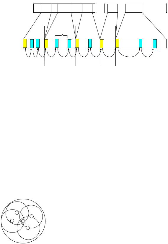
The Wireless USB Host entity implements the host roles of schedule generation and maintenance of the Wireless USB Channel. It is responsible for scheduling data communications on the Wireless USB Channel between itself and Wireless USB devices belonging to the Wireless USB cluster. The host must ensure that it does not schedule Wireless USB channel communications to cross the boundary of a permitted MAC Layer channel access period (i.e. DRP reservation). Figure 4-12 illustrates a view of how the Wireless USB Host operation simplifies this into a series of contiguous (but disjoint in time) time intervals separated by MMCs.
32
Chapter 4 |
|
Data Flow Model |
Wireless Universal Serial Bus Specification, Revision 1.0 |
Figure 4-12. Example Map of Wireless USB Channel to MAC Layer Channel Reservation Boundaries
The logical end of a Transaction Group (as bounded by the mapping onto the MAC Layer Channel in time) must be managed by the Wireless USB host scheduler so that they do not violate MAC Layer channel time structures.
4.3.8.3Host System Management
Host system management controls the interactions and information flow between the Wireless USB Host and MAC Layer compliant device modules, including providing the mapping of the Wireless USB Channel on the PHY via the establishment and maintenance of a series of DRP reservations. Many of the possible functions of this module are beyond the scope of this specification. However it is important to recognize that this module can utilize the services provided by the host and MAC Layer compliant device modules to accomplish the behavior required of a Wireless USB Host and the devices in its cluster. It bridges the Wireless USB Host and MAC Layers such that requirements of each can be converted into structures recognized by the other, for example it can map MAC Layer time onto Wireless USB channel time so that the host time references used by the Wireless USB devices won’t violate the reservation boundaries.
The policy decisions on how to manage MAC Layer channel time for the Wireless USB channel are implemented in a host-specific manner within this module, including how long to hold MAC Layer reservations, when to expand them, when to reduce and when to release them.
4.3.8.4Managing Two-Hop Reservation Topology
If all the neighbors of a Wireless USB device are also neighbors of the host, then the host’s beacon is sufficient to maintain the integrity of the Wireless USB Channel and respect of neighbor’s announced DRP reservations. When the host’s beacon provides coverage for all the devices in its Wireless USB Cluster, there is no benefit for devices in the cluster to transmit MAC Layer Beacons.
D
D
D H
D
Figure 4-13 Host covers all Wireless USB device
33
Chapter 4 |
|
Data Flow Model |
Wireless Universal Serial Bus Specification, Revision 1.0 |
Periodically, the host must check with all members of its Wireless USB Cluster to ensure the neighborhood has not changed. If new MAC Layer compliant devices have entered the radio range of a Wireless USB cluster member device but are not in the range of the host, a Hidden neighbor situation exists, as illustrated in Figure 4-14 where M is hidden from H and could interfere with traffic at the D(s) in its range.
D
D
D H M
D
Figure 4-14 Hidden Neighbor
The host uses the capabilities of Self Beaconing and Directed Beaconing devices to gather information about neighbors in their range and to propagate host beacon information to hidden neighbor devices. Only Directed Beaconing device members of the Wireless USB cluster which have neighbors hidden from the host need to be instructed to transmit and receive packets (e.g. beacons in this particular case).
The host uses the mechanisms described in section 4.3.7.1 to gather reservation information about hidden neighbors from Self Beaconing devices. If the MAS availability information returned by the device is not a superset of the host’s current Wireless USB channel DRP, then it knows there is at least one hidden neighbor and the host may need to adjust its DRP reservations to avoid conflicts.
The host uses the mechanisms described in section 4.3.7.2 to gather similar information from Directed Beaconing devices. The typical process would be that the host first has the device ‘Count Packets’ during the beacon period. The host can then determine if there are any hidden neighbors. If there is a hidden neighbor, the host has the device ‘Capture Packet’ at the appropriate beacon time to get the full beacon of the hidden neighbor. The host can then adjust its DRP reservation if needed.
To direct a device to transmit a beacon, the host uses the Transmit Packet mechanisms defined in section 4.3.7.2.1 to provide the device with a beacon data structure with DRP IEs appropriate for the devices in the neighborhood of the hidden neighbor, as well as a report of the local beacon group constructed to inform the hidden neighbors(s) of the host and its neighbors. The host also provides the device channel time information so that the device will transmit the beacon during the appropriate beacon slot period for multiple MAC Layer superframes.
4.3.8.5Other Host Considerations
If a host does not have any active data flows when a reservation instance begins, it may inform its neighbors that the current reservation time is available for other communications. The MAC Layer standard defines an explicit method for releasing a reservation. The method is based on participants in the reservation transmitting a specific control packet which can be observed by neighbors. A Wireless USB reservation instance is released by the host instructing relevant members of a Wireless USB Cluster to transmit the UDR control packet. Note that the host must transmit the UDR control packet also, see Section 7.5.6. After a DRP instance release operation is complete, the host must not use the DRP instance for Wireless USB communications.
Table 4-1 summarizes how MAC DevAddr values are allocated by a host to manage devices through the process of admittance to a Wireless USB Cluster (see Section 4.13 for details). It is the responsibility of the host to avoid DevAddr value conflicts within its Wireless USB Cluster.
34