

Chapter 4 |
|
Data Flow Model |
Wireless Universal Serial Bus Specification, Revision 1.0 |
Table 4-1. Summary of how MAC Layer DevAddr Address Space is used for Wireless USB
Address Tag |
Range |
Explanation |
|
|
|
MAC Layer Generated, Multicast and |
256-65535 |
Wireless USB Hosts must have a full |
Broadcast DevAddr Range |
(0100H-FFFFH) |
64-bit MAC Address from which a 16- |
|
|
bit DevAddr is generated. The MAC |
|
|
Layer also assigns addresses in the |
|
|
upper portion of this range to Multicast |
|
|
and Broadcast DevAddrs. |
UnConnected_Device_Address |
255 (00FFH) |
A Wireless USB device will use this |
|
|
DevAddr value for its Wireless USB |
|
|
DevAddr when it is in the |
|
|
UnConnected device state. |
UnAuthenticated_Device_Address_Range |
128-254 |
A Wireless USB Host may assign a |
|
(0080H-00FEH) |
connecting device a Device Address |
|
|
in this range in response to a |
|
|
DN_Connect notification. It will also |
|
|
choose an address in this range to |
|
|
serve as the Broadcast Cluster ID. |
WUSB_Device_Address_Range |
0-127 |
The host will assign a device a Device |
|
(0000H-007FH) |
Address in this range as part of the |
|
|
normal enumeration process. |
4.4Data Transfers
Wireless USB preserves all of the basic Data Flow and Transfer concepts defined in USB 2.0, including the Transfer Types, Pipes and basic data flow model. The differences with USB 2.0 are enumerated below, starting with description of differences at the protocol level, then the differences in transfer type constraints.
The USB 2.0 specification utilizes a serial transaction model. This essentially means that a host starts and completes one bus ‘transaction’ {Token, Data, Handshake}, before starting the next transaction. ‘Split’ transactions also adhere to this same model as they are comprised of complete high-speed transactions {Token, Data, Handshake} that are completed under the same model as all other transactions.
Wireless USB maps the USB 2.0 transaction protocol onto the TDMA Micro-scheduling feature. The result is that the Wireless USB transaction protocol is essentially a split-transaction protocol that allows more than one ‘bus transaction’ to be active on the bus at the same time. The split-transaction protocol scales well (across multiple transactions to multiple function endpoints) with signaling bit-rates as it is not completely subject to propagation delays. The basic USB protocol is recognizable within the Wireless USB split transaction architecture, however there are modifications to certain aspects of the protocol in order to reduce or hide some protocol overheads.
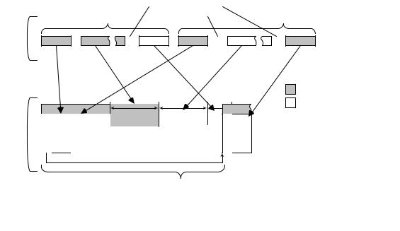
Figure 4-15 illustrates the high-level differences between the USB 2.0 “one at a time” transaction protocol and the basic structure of the Wireless USB protocol.
35
Chapter 4 |
|
Data Flow Model |
Wireless Universal Serial Bus Specification, Revision 1.0 |
Figure 4-15. USB 2.0 vs Wireless USB Transaction Footprints
The USB 2.0 protocol completes an entire IN or OUT transaction (Token, Data and Handshake phases) before continuing to the next bus transaction for the next scheduled function endpoint. The Wireless USB protocol broadcasts USB Token (equivalents) in the MMC and utilizes TDMA time slots for the Data and Handshake phases as appropriate for the transfer type and direction of data communication. Utilizing this method, a host can ‘start’ a group of transactions at the same time (e.g. because the MMC may contain ‘Tokens’ for more than one Wireless USB transaction). Within the context of the Wireless USB application, the Micro-scheduled sequence (e.g. MMC plus associated time slots) is called a Transaction Group. A Wireless USB Host determines how individual transactions are scheduled into individual transaction groups in order to satisfy the needs (and priorities) of the applications controlling the devices in the Wireless USB Cluster. Figure 4-15 illustrates a transaction group with an OUT followed by an IN compared with the same sequence of transactions using the USB 2.0 protocol.
The token blocks in the MMC (Figure 4-15) actually contain several important pieces of information, including Token information (device, endpoint, direction, etc.) and a description of the time slot for the Data or Handshake phase of the transaction. A host must order the time slots in a transaction group so that all of the host-to-device data phases (OUTs) are scheduled to run first in the transaction group (directly following the MMC) then the host will schedule all of the device-to-host time slots. The host must also construct the MMC so that WXCTAs are in time-slot order.
The bit signaling rates provided by the device PHY implementation are nominally available across all function endpoints provided by a device implementation. The signaling rate capabilities of a device are reported in the Wireless USB Device Capabilities descriptor, see Section 7.4.1.1. The host selects the packet bit transfer rate for data phase data packets based on a number of criteria, including: the channel conditions and transfer type constraints defined in Sections 4.5, 4.6, 4.7, and 4.8. For host to device transactions, a host must transmit data phase packets based on the current configured characteristics of the addressed function endpoint. Configured characteristics in this context are associated with the currently active (configured) device/interface configuration characteristics. For device to host transactions, (i.e. data phase packet transmissions), the host directs the device on bit transfer rate, function endpoint payload size and burst size to use per data phase. The host must adhere to the constraints of the transfer type and advertised capabilities of the function endpoint.
Endpoint maximum packet sizes in this specification indicate ‘application’ data payloads only. They do not include any of the MAC or PHY Layer components or any of the security encapsulation or Wireless USB header overhead components. See Section 5 for details.
36