


Chapter 4 |
|
Data Flow Model |
Wireless Universal Serial Bus Specification, Revision 1.0 |
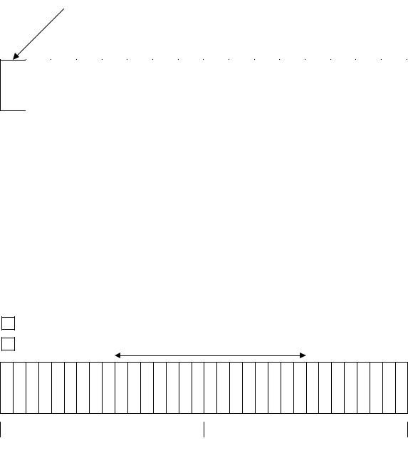
Figure 4- 21.
21.  Typical and Worst
 Case Service Intervals
 For HS Isochronous Endpoint

The typical gap between the start of service opportunities for the device will be 125 microseconds. However, the service can occur at any point in the service interval.
In wired USB the indexed frames (or microframes) provide a bus clock. Isochronous streams can be specified to start in specific frames (microframes). Typically, data that is produced in frame (microframe) X-1 by a wired isochronous IN device is sent across the bus in frame X. A typical wired USB isochronous endpoint needs only two frames (microframes) of buffering.
4.11.1.1Wireless Service Intervals
As with wired USB, Wireless USB isochronous endpoints can receive service anywhere in the service interval. Furthermore, if a Wireless USB isochronous endpoint requires multiple packets per service interval (a maximum burst size bigger than one) the packet transmit/receive opportunities may be distributed as bursts from size 1 to the maximum bust size in any fashion throughout the service interval.
4.11.2UWB Media Characteristics
4.11.2.1Superframe Layout
The Wireless USB isochronous model is designed to work with a specific worst case superframe layout. The model does not assume that the Wireless USB host can reserve all of the time in the superframe. This section defines some terminology that divides the superframe into smaller structures. A superframe is shown Figure 4-22 divided into 16 regions called sections.
The sections are numbered from 0 to 15 from left to right in the superframe. Each section contains 16 MAS time slots of 256 microseconds each.
One section is reserved for transmitting beacons. This section is shown in Figure 4-22.
59
Chapter 4 |
|
Data Flow Model |
Wireless Universal Serial Bus Specification, Revision 1.0 |
Figure 4-22. Beacon Reservation In MAC Layer Superframe
A Wireless USB device will not get service during the reserved beacon period. It also will not be able to get service during times when other Wireless USB devices have reservations. If the Wireless USB host is sharing the channel with other UWB devices (other Wireless USB hosts or non-USB UWB devices) there will be additional times when a Wireless USB isochronous device can not receive service. An isochronous device must account for service gaps to provide functionality in a variety of PHY channel conditions.
4.11.2.2Worst Case Superframe Layout – Service Interval Bounds.
In some cases, the Wireless USB host will need to share the channel with other UWB devices that have already established their reservations. If there are no policies on the way UWB devices take reservations, the largest service interval bound approaches the size of the superframe. Figure 4-23 shows a situation where the service interval approaches the superframe size:
Figure 4-23. Large Wireless USB Host Service Interval Gap
Under coexistence policies, a device that is admitted by the host can expect to receive service with a worst case service interval of 8.192 milliseconds. The worst case service interval occurs between the section at the end of one superframe and the section after the beacon period in the next superframe. Figure 4-24 shows a typical allocation for a Wireless USB host:
60