
- •TABLE OF CONTENTS
- •1.1 Motivation
- •1.2 Design Goals
- •1.3 Objective of the Specification
- •1.4 Scope of the Document
- •1.5 USB Product Compliance
- •1.6 Document Organization
- •2.1 Terms
- •2.2 Conventions:
- •2.3 References
- •3.1 USB System Description
- •3.1.1 Topology
- •3.1.1.1 USB Host
- •3.1.1.2 Wireless USB Devices
- •3.2 Physical Interface
- •3.3 Power Management
- •3.4 Bus Protocol
- •3.5 Robustness
- •3.5.1 Error Handling
- •3.6 Security
- •3.7 System Configuration
- •3.7.1 Attachment of Wireless USB Devices
- •3.7.2 Removal of Wireless USB Devices
- •3.7.3 Bus Enumeration
- •3.8 Data Flow Types
- •3.9 Wireless USB Devices
- •3.9.1 Device Characterizations
- •3.9.2 Devices and MAC Layer
- •3.10 Wireless USB Host: Hardware and Software
- •4.1 Implementer Viewpoints
- •4.2 Communications Topology
- •4.2.1 Physical Topology
- •4.3 Wireless USB Communication Flows
- •4.3.1 Wireless USB Channel Time
- •4.3.2 MMC Transmission Accuracy
- •4.3.3 USB Time across Device Wire Adapters
- •4.3.5 Device Endpoints
- •4.3.6 Wireless USB Information Exchange Methods
- •4.3.7 Device Perspective
- •4.3.7.1 Self Beaconing Devices
- •4.3.7.2 Directed Beaconing Devices
- •4.3.7.3 Non Beaconing Devices
- •4.3.7.4 Selecting A Wireless USB Host
- •4.3.8 Host Perspective
- •4.3.8.1 MAC Layer Compliant Device
- •4.3.8.2 Wireless USB Host
- •4.3.8.3 Host System Management
- •4.3.8.5 Other Host Considerations
- •4.4 Data Transfers
- •4.4.1 Burst Mode Data Phase
- •4.5 Bulk Transfers
- •4.5.1 Bulk Transfer Packet Size and Signaling Rate Constraints
- •4.5.2 Bulk Transfer Channel Access Constraints
- •4.5.3 Bulk Transfer Data Sequences
- •4.6 Interrupt Transfers
- •4.6.1 Low Power Interrupt IN
- •4.6.2 Interrupt Transfer Packet Size and Signaling Rate Constraints
- •4.6.3 Interrupt Transfer Channel Access Constraints
- •4.6.4 Interrupt Transfer Data Sequences
- •4.7 Isochronous Transfers
- •4.7.1 Isochronous Transfer Packet Size and Signaling Rate Constraints
- •4.7.2 Isochronous Transfer Channel Access Constraints
- •4.7.3 Isochronous Transfer Data Sequences
- •4.7.4 Isochronous Endpoint Host System Admission Decisions
- •4.7.5 Isochronous Data Discards and Use of Isochronous Packet Discard IE
- •4.8 Control Transfers
- •4.8.1 Control Transfer Packet Size and Signaling Rate Constraints
- •4.8.2 Control Transfer Channel Access Constraints
- •4.8.3 Control Transfer Data Sequences
- •4.8.4 Data Loopback Commands
- •4.9 Device Notifications
- •4.10 Media Reliability Considerations
- •4.10.1 Transmit Power Control
- •4.10.2 Adjustments to Data Phase Packet Payload Sizes
- •4.10.3 Adjustments to Transmit Bit Rate
- •4.10.4 Changing PHY Channel
- •4.10.5 Host Schedule Control
- •4.10.6 Dynamic Bandwidth Interface Control
- •4.11 Special Considerations for Isochronous Transfers
- •4.11.1 Summary Of Key Features Of USB Wired Isochrony
- •4.11.1.1 Wireless Service Intervals
- •4.11.2 UWB Media Characteristics
- •4.11.2.1 Superframe Layout
- •4.11.2.2 Worst Case Superframe Layout – Service Interval Bounds.
- •4.11.2.3 Wireless Packet Error Rates
- •4.11.3 Wireless USB Isochronous Transfer Level Protocol
- •4.11.4 Wireless USB Isochronous IN Example
- •4.11.5 Wireless USB Isochronous OUT Example
- •4.11.6 Choosing an Isochronous IN or Isochronous OUT Endpoint Buffer Size
- •4.11.7 Isochronous OUT endpoint receiver implementation options
- •4.11.7.1 Presentation Time aware implementation
- •4.11.7.2 Presentation time aware implementation with “false” acknowledgement
- •4.11.7.3 Presentation time unaware implementations
- •4.11.8 Synchronization
- •4.11.8.1 Synchronizing a Stream Start Time
- •4.11.9 Error Handling Details
- •4.11.9.1 Reporting Data Discarded At the Transmitter
- •4.11.9.2 Discarding Data during A Burst
- •4.11.9.3 Application Handling of Discards
- •4.12 Device Reset
- •4.13 Connection Process
- •4.13.1 Reconnection Process
- •4.14 Disconnect
- •4.15 Security Mechanisms
- •4.15.1 Connection Lifetime
- •4.15.2 Host Security Considerations
- •4.15.2.1 CHID Selection
- •4.15.2.2 CDID Selection
- •4.16 Wireless USB Power Management
- •4.16.1 Device Power Management
- •4.16.1.1 Device Sleep
- •4.16.1.2 Device Wakeup
- •4.16.2 Host Power Management
- •4.16.2.1 Channel Stop
- •4.16.2.2 Remote Wakeup
- •4.16.2.3 Channel Start
- •4.17 Dual Role Devices (DRD)
- •4.17.2 Pairing P2P-DRD to establish reverse link
- •5.1 Packet Formats
- •5.2 Wireless USB Transaction Groups
- •5.2.1 Wireless USB Channel Time Allocation Information Elements
- •5.3 Transaction Group Timing Constraints
- •5.3.1 Streaming-Mode Inter-packet Constraints for the PHY
- •5.3.2 Protocol Synchronization
- •5.4 Data Burst Synchronization and Retry
- •5.5 Wireless USB Transactions
- •5.5.1 Isochronous Transactions
- •5.5.2 Control Transfers
- •5.5.3 Device Notifications
- •5.5.4 Flow Control
- •6.1 Introduction
- •6.1.1 Goal of USB Security
- •6.1.2 Security and USB
- •6.2 Overview
- •6.2.1 Base of Trust
- •6.2.2 Preserve the Nature of the USB Device Model
- •6.2.3 Implementation of Security Extensions
- •6.2.4 Encryption Methods
- •6.2.5 Message Format
- •6.2.6 Encryption Keys
- •6.2.6.1 Master Keys
- •6.2.6.2 Session Keys
- •6.2.7 Correct key determination
- •6.2.8 Replay Prevention
- •6.2.9 Secure Packet Reception
- •6.2.10 General Connection Model
- •6.2.10.1 Connection Context
- •6.2.10.2 Connection Lifetime
- •6.2.10.3 New Connection
- •6.2.10.4 Connection
- •6.2.10.5 Reconnection
- •6.2.10.6 Revocation
- •6.2.10.8 Diagnostic Support
- •6.2.10.9 Mutual Authentication
- •6.2.11 Key Management
- •6.2.11.1 PTK Management
- •6.2.11.2 GTK Management
- •6.3 Association and Authentication
- •6.3.1 Connection and Reconnection Requests
- •6.3.2 Authentication
- •6.3.2.1 Authentication Related Device Capabilities
- •6.3.2.2 Ceremonies
- •6.4.1 CCM nonce Construction
- •6.4.2 l(m) and l(a) Calculation
- •6.4.3 Counter-mode Bx Blocks
- •6.4.4 Encryption Ax Blocks
- •6.5.1 Key Derivation
- •6.5.2 Out-of-band MIC Generation
- •6.5.3 Example Random Number Generation
- •7.1 Wireless USB Device States
- •7.1.1 UnConnected
- •7.1.2 UnAuthenticated
- •7.1.3 Authenticated
- •7.1.4 Reconnecting
- •7.2 Generic Wireless USB Device Operations
- •7.3 Standard Wireless USB Device Requests
- •7.3.1 Wireless USB Extensions to Standard Requests
- •7.3.1.1 Clear Feature
- •7.3.1.2 Get Status
- •7.3.1.3 Set Address
- •7.3.1.4 Set Feature
- •7.3.1.5 Set Interface DS
- •7.3.1.6 Set WUSB Data
- •7.3.1.7 Data Loopback Write
- •7.3.1.8 DATA Loopback Read
- •7.3.2 Security-related Requests
- •7.3.2.1 Get Security Descriptor
- •7.3.2.2 Set Encryption
- •7.3.2.3 Get Encryption
- •7.3.2.4 Key Management
- •7.3.2.6 Set Security Data
- •7.3.2.7 Get Security Data
- •7.4 Standard Wireless USB Descriptors
- •7.4.1 Device Level Descriptors
- •7.4.1.1 Wireless USB Device Capabilities – UWB
- •7.4.2 Configuration
- •7.4.3 Endpoint
- •7.4.4 Wireless USB Endpoint Companion
- •7.4.5 Security-Related Descriptors
- •7.4.5.1 Security Descriptor
- •7.4.5.2 Key Descriptor
- •7.5 Wireless USB Channel Information Elements
- •7.5.1 Wireless USB Connect Acknowledge IE
- •7.5.2 Wireless USB Host Information IE
- •7.5.3 Wireless USB Channel Change Announcement IE
- •7.5.4 Wireless USB Device Disconnect IE
- •7.5.5 Wireless USB Host Disconnect IE
- •7.5.6 Wireless USB Release Channel IE
- •7.5.7 Wireless USB Work IE
- •7.5.8 Wireless USB Channel Stop IE
- •7.5.9 Wireless USB Device Keepalive IE
- •7.5.10 Wireless USB Isochronous Packet Discard IE
- •7.5.11 Wireless USB Reset Device IE
- •7.5.12 Wireless USB Transmit Packet Adjustment IE
- •7.6 Device Notifications
- •7.6.1 Device Connect (DN_Connect)
- •7.6.1.1 Connect Request
- •7.6.1.2 Reconnect Request
- •7.6.2 Device Disconnect (DN_Disconnect)
- •7.6.3 Device Endpoints Ready (DN_EPRdy)
- •7.6.4 Device MAS Availability Changed (DN_MASAvailChanged)
- •7.6.5 Device Sleep (DN_Sleep)
- •7.6.6 Remote Wakeup (DN_RemoteWakeup)
- •7.6.7 Device Alive (DN_Alive)
- •8.1 Operational Model
- •8.1.1 Functional Characteristics
- •8.1.2 Data Transfer Interface
- •8.1.3 Remote Pipe
- •8.1.4 Wire Adapter Functional Blocks
- •8.1.5 Downstream Port(s)
- •8.1.6 Upstream Port
- •8.1.7 Downstream Host Controller
- •8.1.8 Upstream Endpoint Controller
- •8.1.9 Remote Pipe Controller
- •8.1.9.1 RPipe Descriptor
- •8.1.9.2 Bulk OUT Overview
- •8.1.9.3 Bulk IN Overview
- •8.1.9.4 Control Transfer Overview
- •8.1.9.5 Interrupt Transfer Overview
- •8.1.9.6 Isochronous Transfer Overview
- •8.1.10 Suspend and Resume
- •8.1.10.1 DWA Suspend and Resume
- •8.1.10.2 HWA Suspend and Resume
- •8.1.11 Reset Behavior
- •8.1.12 Device Control
- •8.1.13 Buffer Configuration
- •8.2 Descriptors
- •8.3 Requests
- •8.3.1 Wire Adapter Class-Specific Requests
- •8.3.1.1 Abort RPipe
- •8.3.1.2 Clear RPipe Feature
- •8.3.1.3 Clear Wire Adapter Feature
- •8.3.1.4 Get RPipe Descriptor
- •8.3.1.5 Get RPipe Status
- •8.3.1.6 Get Wire Adapter Status
- •8.3.1.7 Set RPipe Descriptor
- •8.3.1.8 Set RPipe Feature
- •8.3.1.9 Set Wire Adapter Feature
- •8.3.1.10 Reset RPipe
- •8.3.2 Notification Information
- •8.3.3 Transfer Requests
- •8.3.3.1 Control Transfers
- •8.3.3.2 Bulk and Interrupt Transfers
- •8.3.3.3 Transfer Completion Notification
- •8.3.3.4 Transfer Result
- •8.3.3.5 Abort Transfer
- •8.4 DWA Interfaces, Descriptors and Control
- •8.4.1 DWA Isochronous Streaming Interface
- •8.4.2 DWA Isochronous Streaming Overview
- •8.4.3 DWA Descriptors
- •8.4.3.1 Device Descriptor
- •8.4.3.2 Binary Device Object (BOS) Descriptor
- •8.4.3.3 Configuration Descriptor
- •8.4.3.4 Security Descriptors
- •8.4.3.5 Interface Association Descriptor
- •8.4.3.6 Data Transfer Interface Descriptor
- •8.4.3.7 Wire Adapter Class Descriptor
- •8.4.3.8 Notification Endpoint Descriptor
- •8.4.3.9 Notification Endpoint Companion Descriptor
- •8.4.3.10 Data Transfer Write Endpoint Descriptor
- •8.4.3.11 Data Transfer Write Endpoint Companion Descriptor
- •8.4.3.12 Data Transfer Read Endpoint Descriptor
- •8.4.3.13 Data Transfer Read Endpoint Companion Descriptor
- •8.4.3.14 Isochronous Streaming Interface Descriptor
- •8.4.3.15 Isochronous Streaming OUT Endpoint Descriptor
- •8.4.3.16 Isochronous Streaming OUT Endpoint Companion Descriptor
- •8.4.3.17 Isochronous Streaming IN Endpoint Descriptor
- •8.4.3.18 Isochronous Streaming IN Endpoint Companion Descriptor
- •8.4.3.19 Wire Adapter RPipe Descriptor
- •8.4.4 DWA Specific Requests
- •8.4.4.1 Clear Port Feature
- •8.4.4.2 Get Port Status
- •8.4.4.3 Set Isochronous Endpoint Attributes
- •8.4.4.4 Set Port Feature
- •8.4.5 DWA Notification Information
- •8.4.5.1 Remote Wake
- •8.4.5.2 Port Status Change
- •8.4.6 DWA Isochronous Transfers
- •8.4.6.1 DWA Isochronous OUT Responsibilities
- •8.4.6.2 DWA Isochronous IN Responsibilities
- •8.5 HWA Interfaces, Descriptors and Control
- •8.5.1 HWA Isochronous Streaming Overview
- •8.5.2 HWA Descriptors
- •8.5.2.1 Device Descriptor
- •8.5.2.2 Device_Qualifier Descriptor
- •8.5.2.3 Configuration Descriptor
- •8.5.2.4 Other_Speed_Configuration Descriptor
- •8.5.2.5 Security Descriptors
- •8.5.2.6 Data Transfer Interface Descriptor
- •8.5.2.7 Wire Adapter Class Descriptor
- •8.5.2.8 Notification Endpoint Descriptor
- •8.5.2.9 Data Transfer Write Endpoint Descriptor
- •8.5.2.10 Data Transfer Read Endpoint Descriptor
- •8.5.2.11 Wire Adapter RPipe Descriptor
- •8.5.3 HWA Specific Requests
- •8.5.3.2 Get BPST Adjustment
- •8.5.3.3 Get BPST Time
- •8.5.3.4 Get WUSB Time
- •8.5.3.5 Remove MMC IE
- •8.5.3.6 Set Device Encryption
- •8.5.3.7 Set Device Info
- •8.5.3.8 Set Device Key
- •8.5.3.9 Set Group Key
- •8.5.3.10 Set Num DNTS Slots
- •8.5.3.11 Set WUSB Cluster ID
- •8.5.3.12 Set WUSB MAS
- •8.5.3.13 Set WUSB Stream Index
- •8.5.3.14 WUSB Channel Stop
- •8.5.4 HWA Notification Information
- •8.5.4.1 BPST Adjustment Change
- •8.5.4.2 DN Received Notification
- •8.5.5 HWA Isochronous Transfers
- •8.5.5.1 HWA Isochronous OUT Responsibilities
- •8.5.5.2 HWA Isochronous IN Responsibilities
- •8.5.5.3 HWA Isochronous Transfer Completion
- •8.6 Radio Control Interface
- •8.6.1 Radio Control Descriptors
- •8.6.1.1 Radio Control Interface Descriptor
- •8.6.1.2 Radio Control Interface Class Descriptor
- •8.6.1.3 Radio Control Interrupt Endpoint Descriptor
- •8.6.2 Radio Control Command
- •8.6.2.1 Channel Change
- •8.6.2.2 Device Address Management
- •8.6.2.4 Reset
- •8.6.2.5 Scan
- •8.6.2.6 Set Beacon Filter
- •8.6.2.9 Set Notification Filter
- •8.6.2.10 Set TX Power
- •8.6.2.11 Sleep
- •8.6.2.12 Start Beaconing
- •8.6.2.13 Stop Beaconing
- •8.6.3 Radio Control Notifications
- •8.6.3.1 Application-specific Probe IE Received Notification
- •8.6.3.2 Beacon Received Notification
- •8.6.3.3 Beacon Size Notification
- •8.6.3.4 BPOIE Change Notification
- •8.6.3.5 BP Slot Change Notification
- •8.6.3.6 BP Switch IE Received Notification
- •8.6.3.7 Device Address Conflict Notification
- •8.6.3.8 DRP Availability Changed Notification
- •8.6.3.9 DRP Notification
- •A.1 Key Derivation
- •A.2 Handshake MIC calculation
- •A.3 Secure MMC (EO = payload length)
- •A.4 Data IN from device (EO = 2)
- •B.1 Descriptors for DWA
- •B.2 Descriptors for HWA

Chapter 4 |
|
Data Flow Model |
Wireless Universal Serial Bus Specification, Revision 1.0 |
4.4.1Burst Mode Data Phase
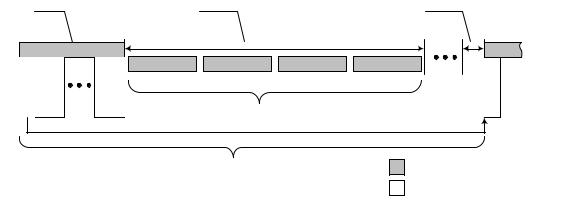
The USB 2.0 protocol allows a maximum of one data packet per USB transaction. Due to the significant packet delimiter overheads for wireless (long packet preambles, MIFS, SIFS, etc.), Wireless USB includes the capability to send multiple data packets during a transaction’s data phase (see Figure 4-16). This feature allows for potentially better efficiency because packet delimiters and inter-packet gaps can be reduced. The general term for this capability is a Burst Mode Data Phase. All Wireless USB Data Phases use the Burst Mode Data Phase rules; even if burst size is one (see Section 5.4).
Figure 4-16. Example WUSB Data Phase Data Burst Footprint
“Data Burst” is a generic term for the series of data packets that are transmitted during the data phase of a Wireless USB transaction (see Figure 4-16). Maximum data burst size is an individual function endpoint capability which depends on the function endpoint’s current configuration. A host determines a function endpoint’s maximum data burst size from its Wireless USB Endpoint Companion descriptor (see Section 7.4.4). The size of each data packet in a data burst must be the configured function endpoint’s maximum packet size or adjusted maximum packet size (see Section 4.10.2), (except for short-packet situations and isochronous streams).
The host may dynamically change the burst size on a per-transaction basis (up to the configured maximum burst size). The detailed description of Wireless USB Data Bursting is provided in Section 5.4.
The host may use any burst size up to the configured maximum burst size. Examples of when a host may use different burst sizes include (but are not limited to) a fairness policy on the host, retries for an isochronous stream, etc. When the function endpoint is an OUT, the host can trivially control the burst size (receiver must always be able to manage a transaction burst size). Note that the host must observe the configured maximum endpoint sequence range as defined below, regardless of the actual burst size it is using. When the function endpoint is an IN, the host can limit the burst size for the function endpoint on a per-transaction basis via a field in the Token block of the MMC (see Section 5.2.1). Note that a host may override the configured burst size by specifying a value less than the configured maximum burst size of the function endpoint.
4.5Bulk Transfers
The purpose and characteristics of Bulk Transfers is similar to that defined in USB 2.0 (Section 5.8 of the USB 2.0 Specification). Chapter 5 of this specification describes the details of the packets, bus transactions and transaction sequences used to accomplish Bulk transfers. Bulk transfer type is intended to support devices that want to communicate relatively large amounts of data at highly variable times where the transfer can use any available Wireless USB channel bandwidth. A Wireless USB Bulk function endpoint provides the following:
•Access to the Wireless USB channel on a bandwidth available basis
•Guaranteed delivery of data, but no guarantee of bandwidth or latency
37
Chapter 4 |
|
Data Flow Model |
Wireless Universal Serial Bus Specification, Revision 1.0 |
Bulk transfers occur only on a bandwidth-available basis. With large amount of channel time and good channel conditions, bulk transfers may happen relatively quickly; for conditions with little channel time available, bulk transfers may take a long time.
Wireless USB retains the following characteristics of bulk pipes:
•No data content structure is imposed on communication flow for bulk pipes
•A bulk pipe is a stream pipe, and therefore always has communication flow either into or out of the host for any pipe instance. If an application requires a bi-directional bulk communication flow, two bulk pipes must be used (one IN and one OUT).
4.5.1Bulk Transfer Packet Size and Signaling Rate Constraints
An endpoint for bulk transfers specifies the maximum data packet payload size and burst size that the endpoint can accept from or transmit to the Wireless USB channel during one transaction. The allowable maximum data payload sizes for bulk endpoints are packet size values between 512 and 3584 that are integral multiples of 512 (i.e. 512, 1024, 1536, 2048, 2560, 3072 and 3584). The maximum allowable burst size bulk endpoints may specify is any value in the range 1 to 16.
A host may use any of the device’s reported PHY signaling rates for data packets transmitted during the data phase of a Wireless USB transaction. For OUT (host to device) transactions to a bulk endpoint, the host may use any supported PHY signaling rate for data packets. For INs (device to host) the host may direct the device to use any one of the supported PHY signaling rates for data packets transmitted during the data phase.
A host is required to support any Wireless USB bulk endpoint. A host must support all combinations of bulk packet sizes and bulk burst sizes. No host is required to support larger than maximum packet sizes. The host ensures that no data payload of any data packet in a transaction burst will be sent to the endpoint that is larger than the reported maximum packet size, it will not send more data packets than the reported maximum burst size and it will not use sequence numbers larger than or equal to the reported maximum sequence value of the endpoint.
As noted in Section 4.10.2 a host may use smaller data payloads per packet than the reported maximum packet size as a measure to improve PER, when the function endpoint reports that it supports data packet size adjustments. For function endpoints that do not support the data packet size adjustment, the host must always use the reported wMaxPacketSize with transactions to the function endpoint. For function endpoints that do support data packet size adjustment, the host may only use allowed data packet sizes less than or equal to the reported maximum packet size for the endpoint. For example, a bulk endpoint reports a wMaxPacketSize of 1536 bytes; a host may only use packet sizes in the set {512, 1024, 1536}. An IN transaction token (WDTCTA, see Section 5.2.1.2) always includes the packet size the function endpoint should use for the data phase data packets. A host must always specify to use a data packet size supported by the function endpoint; otherwise the behavior is not defined. The data packet size selected for each bulk transaction is called the ‘active’ packet size. On OUT transactions, the function bulk endpoint (that supports packet size adjustments) must be prepared for the host to use any valid ‘active’ packet size in each transaction.
A bulk function endpoint must always transmit data payloads with data fields less than or equal to the transaction’s active packet size. If the bulk transfer has more information than will fit into the active packet size for the transaction, all data payloads in the data burst are required to be active packet size except for the last data payload in the burst, which may contain the remaining data. A bulk transfer may span multiple bus transactions. The host is allowed to adjust the active packet size (when the device supports it) on every contiguous burst. See Section 4.10.2 for the definition of a contiguous burst. A bulk transfer is complete when the endpoint does one of the following:
•Has transferred exactly the amount of data expected
•Transfers a data packet with a last packet flag set to one in its Wireless USB header (see Section 5.1).
38