

Atomic physics (2005)
.pdf196 Laser cooling and trapping
Refractive
index Absorption
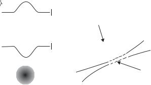
Fig. 9.12 Absorption has a Lorentzian line shape with a peak at the resonance frequency ω0. The refractive index is zero on resonance, where it changes sign, and this characteristic dependence on frequency leads to dispersion.
Incident light
Lens
Fig. 9.13 A tightly-focused beam of light exerts a radiation force on a dielectric sphere that pulls it towards the region of high intensity (at the focus). Not all of the light is transmitted at the interfaces and the reflected rays are indicated. After Ashkin (1997).
B |
A |
|
Focus |
Dielectric |
|
sphere |
|
A B Refracted light
34Generally speaking, the e ects of refraction are most apparent when they are not obscured by absorption, i.e. away from a resonance. A similar situation arises for forces on the individual atoms.
cal model in which bound electrons execute damped harmonic oscillation with resonance frequency ω0, see Section 7.5.1 and Fox (2001), but the relationship between the refractive index and absorption at the resonant frequency is very general (independent of any particular model). Dispersion and absorption are di erent facets of the same interaction of light with matter; strong absorption leads to large changes in refractive index. The variation in the refractive index extends over a larger frequency range than the absorption, e.g. although air and glass (of good optical quality) are both transparent at visible wavelengths they have refractive indices of 1.0003 and 1.5, respectively, associated with strong absorption in the ultraviolet region; nglass − 1 nair − 1 because a solid has a higher density of atoms than a gas.34
The force that attracts an object towards a region of high intensity has been used to manipulate microscopic objects in a technique called optical tweezers that was developed by Arthur Ashkin (Ashkin et al. 1986). The objective lens in an optical microscope is used to focus a laser beam tightly so that there is a strong gradient force along the axis, as shown in Fig. 9.13, in addition to trapping in the radial direction

9.6 Theory of the dipole force 197
shown in Fig. 9.11. As the laser beam is moved the particles remain trapped in the region of high intensity. The microscope is used to view the object through a filter that blocks the laser light. The objects are immersed in water and mounted on a microscope slide in a standard way. The liquid provides viscous damping of the motion.35 Optical tweezers works, not just for simple spheres, but also for biological cells such as bacteria, and these living objects can withstand the focused intensity required to trap them without harm (the surrounding water prevents the cells from heating up). For example, experiments have been carried out where a bacterium is tethered to the surface of a glass microscope slide by its flagellum (or ‘tail’) and the body is moved around by optical tweezers. This gives a quantitative measure of the force produced by the microscopic biological motor that moves the flagellum to propel these organisms (see Ashkin (1997) and Lang and Bloch (2003) for reviews).
This section has introduced the concept of a radiation force called the gradient force, or dipole force, and the next section shows that a similar force occurs for atoms.36
35Laser radiation can levitate small objects in air, but this is less straightforward than the manipulation of objects floating in water.
36This analogy is not just of pedagogical interest—the first experiments on optical tweezers and the dipole-force trapping of atoms were carried out in the same place (Bell Laboratories in the USA).
9.6Theory of the dipole force
Actually, this section does not just derive the dipole force on an atom from first principles but also the scattering force, and so demonstrates the relationship between these two types of radiation force. An electric field E induces a dipole moment of −er = 0χaE on an atom with a (scalar) polarizability 0χa. The interaction energy of this dipole with the electric field is given by
U = − |
1 |
0χaE2 = |
1 |
er · E , |
(9.34) |
2 |
2 |
where E is the amplitude of the electric field and U is used here to denote energy to avoid confusion with the electric field. This expression comes from the integration of dU = − 0χaE dE from E = 0 to E = E (the factor of 1/2 does not occur for a permanent electric dipole). Di erentiation gives the z-component of the force as
Fz = − |
∂U |
= 0χaE |
∂E |
, |
(9.35) |
|
|
||||
∂z |
∂z |
and similarly for Fx and Fy . Radiation of angular frequency ω, propagating along the z-direction, can be modelled as an electric field E = E0 cos (ωt − kz) ex.37 The gradient of the energy gives the z-component of the force as38
Fz = −ex |
∂E |
|
∂z0 cos (ωt − kz) + kE0 sin (ωt − kz) . |
(9.36) |
The two parts of this force can be understood using either the classical or the quantum mechanical expressions for the dipole that were derived in Chapter 7. The classical model of the atom as an electron undergoing
37This particular field is linearly polarized parallel to ex, as in Section 7.3.2, but the results derived here are quite general.
38This classical treatment gives the same result as the quantum mechanical derivation when the electric field varies slowly over the typical dimensions of an atomic wavepacket (λdB
λlight). Under these circumstances, classical equations of motion corre-
spond to equations for the expectation values of the quantum operators, e.g. the rate of change of momentum equals the force corresponding to
d p = −U . dt
This is an example of Ehrenfest’s theorem in quantum mechanics. The quantum mechanical derivation of the dipole force is given in Cohen-Tannoudji et al. (1992).

198 Laser cooling and trapping
39As shown in Section 7.5.1, the classical model does not account for saturation.
40Using sin2 = cos2 = 12 .
41In optics, it is generally the e ect of the medium on the light that is of interest, e.g. the angle through which the medium refracts, or bends, a light beam, but this implies that the medium feels a force equal to the rate of change of the momentum of the light. The refractive index, and absorption coe - cient, describe bulk properties, whereas it is the e ect of light on individual atoms that is of interest here.
simple harmonic motion gives very useful insight into the frequency dependence of the force, but the quantum treatment is required to find the correct intensity dependence.39 This section presents both approaches, starting with the classical one—because of the very close parallels between them this requires little extra e ort.
Classically, the displacement of the electron x by an electric field is calculated by modelling the atom as a harmonic oscillator with a driving term. Expressing x in terms of its components in phase (U) and in quadrature (V) to the applied field (cf. eqn 7.56), we find
Fz = −e {U cos (ωt − kz) − V sin (ωt − kz)}
× |
∂E |
(9.37) |
0 |
cos (ωt − kz) + E0k sin (ωt − kz) . |
|
∂z |
The time average over many oscillation periods gives40
|
|
|
= |
−e |
|
∂E0 |
|
kE |
|
|
|
|
|
F |
|
|
|
|
|
||||||
|
|
U |
∂z − V |
|
|
|
||||||
|
|
z |
2 |
0 |
|
|
|
|
||||
|
|
= |
e2 |
|
−(ω − ω0)E0 |
∂E0 |
+ |
(β/2)kE02 |
, |
|||
|
|
4mω |
(ω − ω0)2 + (β/2)2 ∂z |
(ω − ω0)2 + (β/2)2 |
||||||||
|
|
|
|
|
|
|||||||
|
|
|
|
|
|
|
|
|
|
|
|
(9.38) |
using1 eqns 27.58 and 7.59 for U and V. |
The intensity of the light is |
|||||||||||
I = 2 |
0cE0 and, by a simple extension of the derivation given above |
|||||||||||
to the x- and y-directions, the radiation force can be written in vector notation as
|
= |
e2 |
|
−(ω − ω0) |
I |
+ |
β/2 |
|
I |
|
k |
. |
|
F |
|||||||||||||
2 0mc |
(ω − ω0)2 + (β/2)2 ω |
|
|
|
|||||||||
|
|
|
(ω − ω0)2 + (β/2)2 c |k| |
||||||||||
(9.39) The in-phase component of the dipole (U) leads to a force proportional to the gradient of the intensity. The frequency dependence of this component follows a dispersive line shape that is closely related to the refractive index,41 as shown in Fig. 9.12. (The dependence on 1/ω has a negligible e ect on narrow transitions β ω0.) At the atomic resonance frequency ω = ω0 the component U = 0. The quadrature term, from V, has a Lorentzian line shape and this force, arising from absorption, is proportional to I and points along the wavevector of the radiation k. This classical model gives a simple way of understanding various important features of the forces on atoms and shows how they relate to radiation forces on larger objects (such as those discussed in the introductory Sections 9.1 and 9.5); however, we shall not use it for quantitative calculations.
To find the force quantum mechanically, we use eqn 7.36 for the dipole moment in terms of the components of the Bloch vector u and v. Substitution into eqn 9.36, and taking the time average as above, gives (cf.
eqn 9.38) |
|
|
|
|
|
|
|||
|
|
|
|
eX |
12 |
|
∂E |
|
|
|
Fz = |
− |
|
u |
0 |
− vE0k |
(9.40) |
||
|
|
2 |
|
∂z |
|||||
|
|
= Fdipole + Fscatt . |
(9.41) |
||||||

9.6 Theory of the dipole force 199
The force that depends on the in-phase component of the dipole u is the dipole force and the other part is the scattering force. Using the expressions for u and v given in eqn 7.68 and the Rabi frequency Ω = eX12E0/ , we find that
Fscatt = k |
Γ |
Ω2/2 |
|
|
, |
|
|
(9.42) |
|||||
2 |
|
δ2 + Ω2/2 + Γ2/4 |
|
|
|||||||||
which is consistent with eqn 9.4, and |
|
|
|
|
|
|
|
||||||
Fdipole = − |
δ |
Ω |
|
∂Ω |
, |
(9.43) |
|||||||
|
|
|
|
|
|
|
|||||||
2 |
|
δ2 + Ω2/2 + Γ2/4 |
∂z |
||||||||||
where δ = ω − ω0 is the frequency detuning from resonance. The expression for the scattering force has been repeated here for ease of comparison with eqn 9.43. These forces have essentially the same frequency dependence as in the classical model, with a line width that is power broadened so that β ←→ Γ(1 + 2Ω2/Γ2)1/2. The dipole force is zero on resonance (Fdipole = 0 for δ = 0), and for |δ| Γ (and an intensity such that |δ| Ω) the dipole force equals the derivative of the light shift
(eqn 7.93): |
|
|
Ω2 |
. |
|
Fdipole − |
∂ |
(9.44) |
|||
∂z |
4δ |
Thus the light shift, or a.c. Stark shift, for an atom in the ground state acts as a potential Udipole in which the atom moves. More generally, in three dimensions
|
|
∂ |
|
∂ |
|
|
∂ |
Udipole = − Udipole , |
(9.45) |
||||||||
where |
|
|
|
|
|
||||||||||||
|
|
|
|||||||||||||||
Fdipole = − |
ex ∂x |
+ ey ∂y |
+ ez ∂z |
||||||||||||||
|
|
|
|
|
|
|
Ω2 |
|
Γ Γ I |
(9.46) |
|||||||
|
|
Udipole |
|
|
≡ |
|
|
|
|
|
|
. |
|||||
|
|
|
4δ |
8 |
δ |
Isat |
|||||||||||
When δ is positive (ω > ω0) this potential has a maximum where the intensity is highest—the atom is repelled from regions of high intensity. In the opposite case of frequency detuning to the red (δ negative) the dipole force acts in the direction of increasing I, and Udipole is an attractive potential—atoms in a tightly-focused laser beam are attracted towards the region of high intensity, both in the radial direction and along the axis of the beam. This dipole force confines atoms at the focus of a laser beam in an analogous way to optical tweezers to create a dipole-force trap.42 Normally, dipole traps operate at large frequency detuning (|δ| Γ), where to a good approximation eqn 9.3 becomes
Rscatt |
Γ Γ2 I |
(9.47) |
8 δ2 Isat . |
This scattering rate depends on I/δ2, whereas the trap depth is proportional to I/δ (in eqn 9.46). Thus working at a su ciently large frequency detuning reduces the scattering whilst maintaining a reasonable trap depth (for a high intensity at the focus of the laser beam). Usually
42The situation for an atom with detuning δ < 0 resembles that of a dielectric sphere with a refractive index greater than the surrounding medium.

200 Laser cooling and trapping
43Whereas for scattering-force techniques the frequency of the laser must be tunable, so that it can be adjusted to within several line widths from an atomic transition frequency.
there are two important criteria in the design of dipole-force traps: (a) the trap must be deep enough to confine the atoms at a certain temperature (that depends on the method of cooling); and (b) the scattering rate must be low to reduce heating.
Example 9.2 Dipole trapping of sodium atoms
The wavelength of the laser light used for a dipole-force trap depends mainly on practical considerations.43 It is convenient to use a highpower solid-state laser such as a Neodymium:YAG laser that produces continuous-wave radiation at a fixed infra-red wavelength of λ = 1.06 µm. The frequency detuning of this laser radiation from the sodium resonance at λ0 = 589 nm is
δ |
= |
2π |
|
c |
− |
c |
= 2.3 × 10⁷ , |
(9.48) |
|
Γ |
|
Γ |
|
λ0 |
λ |
||||
44This frequency detuning δ 12 ω0, so that the rotating-wave approximation is not very good.
in units of Γ, where 1/Γ = τ = 16 ns.44 Solid-state lasers can produce powers of many tens of watts, but in this example we use a conservative value of P = 1 W. When focused to a waist of w0 = 10 µm this laser beam has an intensity of I = 2P/(πw02) = 6.4×10⁹ W m−2 ≡ 1×10⁸ Isat. Equation 9.46 gives
Udipole = |
Γ |
× 1.1 = 260 µK . |
(9.49) |
2 |
Thus atoms cooled below the Doppler cooling limit Γ/2 can be trapped. For this laser intensity and frequency detuning, eqn 9.47 gives
Rscatt = 2.4 × 10⁻⁸ Γ = 2 s−1 . |
(9.50) |
45If atoms gain twice the recoil energy per scattering event, as in eqn 9.24, it takes many seconds before the atoms boil out of the trap. The fluctuations in the dipole force itself can cause heat-
ing and Fdipole + δFdipole should be included in eqn 9.20. The fluctuations
δFdipole give comparatively small heating in a dipole-force trap with a large
frequency detuning; however, there are
circumstances where δFdipole is the dominant cause of heating, e.g. for the
Sisyphus e ect described in Section 9.7.
46Writing eqn 9.50 as
Rscatt = 5 × 10⁻⁸ (Γ/2) ,
where Γ/2 is the maximum of Rscatt, shows that Fscatt times its maximum value.
A sodium atom only scatters a few photons per second which gives a low heating rate.45 The scattering force is negligible for these conditions,46 i.e. the force pushing in the direction of the light is weaker than the dipole force pulling the atom towards the high-intensity focus. The condition that the laser light has a frequency detuning far from the atomic resonance is not restrictive, and calculations along the same lines as that given here for sodium show that a laser with the above properties can be used for the dipole-force trapping of any alkali metal atom.
A force derived from a potential is conservative, i.e. the total energy remains constant during motion. Thus an atom that enters a dipole trap gains kinetic energy as it moves towards the bottom of the potential well and then it rides up the other side of the trap and escapes, because no energy is lost. To load a dipole trap there must be either some dissipation of energy by spontaneous emission (as in the MOT), or the atoms must be placed gently in the bottom of the trap. In the first experimental demonstration of a dipole trap for atoms the laser beam was focused into a cloud of atoms that were cooled by the optical molasses technique, see Fig. 9.14 (Chu et al. 1986). The trapped atoms were observed as a bright spot in the region of more di use fluorescence from
9.6 Theory of the dipole force 201
(a) |
(b) |
Atoms in optical molasses
Laser |
Dipole |
trap |
|
beam |
|
Fig. 9.14 (a) An intense laser beam alters the energy levels of an atom, as illustrated for a radial direction across a laser beam propagating perpendicular to the plane of the figure. For a laser frequency less than the atomic resonance frequency the a.c. Stark e ect forms a potential well in the groundstate energy and atoms are attracted towards regions of high intensity. (b) The dipole-force trap formed by a focused laser beam can be loaded with cold atoms produced by the optical molasses technique, as described in the text.
the region of optical molasses because the density of trapped atoms was greater. When the focused laser beam was first switched on the dipole trap contained relatively few atoms within its small volume, at a density comparable with that in the surrounding region, e.g. 1010 cm−3. This was perceived to be a problem, but atoms that started o outside the trap executed a random walk47 that took some of them into the dipole trap, where they remained. In this way atoms accumulated in the trap to give a high density.
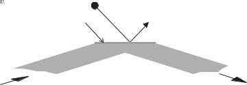
A dipole-force trap formed by a single laser beam gives tight radial confinement, but it is weak in the axial direction. Therefore the atoms in such a trap form an elongated, cigar-shaped cloud. To obtain strong confinement in all directions, if necessary, one can form a dipole-force trap at the intersection of two laser beams.48 Many other configurations are possible and the design of dipole traps is restricted only by the form of the intensity distributions that can be sculpted from laser light. Di raction limits the minimum distance over which the intensity of the light changes. An ingenious way of creating a high-intensity gradient is shown in Fig. 9.15. A laser beam that is totally internally reflected at the surface of glass gives an evanescent wave in which the electric field falls o exponentially over a distance of the wavelength of the light.49 For a laser frequency to the blue (δ > 0), the repulsive dipole force near the surface acts like a reflective coating for atoms. This creates a mirror that reflects low-energy atoms, as shown in Fig. 9.15.
9.6.1Optical lattice
The dipole force is strong in a standing wave of light because the intensity changes from a maximum (at the anti-nodes) to zero (at the nodes) over a distance of λ/2 to give a high gradient of intensity. The physical explanation for this strong force is stimulated scattering of radiation. In a standing wave, an atom absorbs light with wavevector k from one beam and the laser beam in the opposite direction stimulates emission with wavevector k = −k; this gives the atom an impulse of 2k. The rate of this stimulated process does not saturate at high intensities.50
47A random walk in space leading to spatial di usion, rather than the random walk of the velocity leading to heating that was used to calculate the Doppler cooling limit—both processes are caused by scattering.
48The dipole potential is proportional to the total intensity. Laser beams with orthogonal polarizations, or substantially di erent frequencies, do not interfere and the total intensity is the sum of the individual intensities.
49This behaviour of the light closely resembles the quantum reflection at a potential step that is higher than the energy of the incident particle. The wavefunction falls exponentially to zero in the classically forbidden region.
50More generally, the dipole force arises from a stimulated process of absorption of a photon of wavevector k1 and stimulated emission with wavevector k2. In this process the atom receives an impulse (k1 − k2) that changes the atom’s momentum. A tightly-focused laser beam contains a range of wavevectors and exerts a dipole force on an atom analogous to that in the optical tweezers technique. A dipole force cannot occur in a plane wave since the stimulated processes
have k1 = k2.
202 Laser cooling and trapping
|
Slow atom |
|
|
|
Evanescent |
|
|
Fig. 9.15 The evanescent wave, cre- |
wave |
Vacuum |
|
|
|
|
|
ated when a laser beam is totally in- |
|
|
|
ternally reflected, forms a mirror for |
|
|
Glass |
atoms. For a light with a blue detun- |
|
|
|
ing (ω > ω0) the dipole force repels |
|
|
|
atoms from the region of high inten- |
|
|
|
sity close to the vacuum–glass interface. |
|
|
|
(The same principle applies if the sur- |
Laser beam |
|
|
face is curved (e.g. concave) and such |
|
|
|
an arrangement can be used to focus |
|
|
|
the matter waves.) |
|
|
|
|
|
|
|
51This form is only true for large detunings, δ Γ, Ω. If this inequality is satisfied then there is also little spontaneous scattering from the atoms.
52Interference will generally lead to a periodic arrangement of positions where atoms become localised (at intensity maxima for a frequency detuning to the red) in a three-dimensional standing wave of light, but the creation of a particular configuration of the optical lattice requires control of the polarization (and relative phase).
53The phase-space density at which BEC occurs is approximately equal to that at which there is one atom per well in the ground state of an optical lattice.
54As atoms pass through a standing wave of light they accumulate a phase shift of order φ U0t/ for an interaction time t. Light with either sign of frequency detuning can be used to give φ ±π, and so create a phase grating with significant amplitude in the diffraction orders.
The dipole potential associated with this force depends on the intensity of the light (cf. eqn 9.46 for a large frequency detuning). Two counter-propagating beams of linearly-polarized light produce an electric field given by
E = E0 cos (ωt − kz) + cos (ωt + kz) } ex |
|
||
= 2E0{cos (kz) cos (ωt) ex . |
|
(9.51) |
|
This standing wave gives a dipole |
potential of the form51 |
|
|
|
|
|
|
Udipole = U0 cos2 (kz) . |
|
(9.52) |
|
Here U0 is the light shift at the anti-nodes—these maxima have an intensity four times that of the individual beams. For a frequency detuning to the red, a standing wave of light traps atoms at the anti-nodes and gives confinement in the radial direction as in a single beam. This regular array of microscopic dipole traps is called an optical lattice. With more laser beams the interference between them can create a regular array of potential wells in three dimensions, e.g. the same configuration of six beams in the optical molasses technique shown in Fig. 9.5 (along
±ex, ±ey and ±ez ) can create a regular cubic lattice of potential wells for suitable polarizations and a large frequency detuning.52 The potential wells in this optical lattice have a spacing of λ/2, and so one atom per lattice site corresponds to a density of 8/λ3 7 × 1013 cm−3 for λ = 1.06 µm. Therefore the sites will be sparsely populated when the atoms are loaded into the lattice after cooling by the optical molasses technique. (A typical number density in the optical molasses technique is a few times 1010 cm−3 ≡ 0.01 atoms µm−3.)
Experiments that load more than one atom in each potential well have been carried out by adiabatically turning on the light that creates an optical lattice in a region containing a sample of atoms that are in a Bose–Einstein condensate (see Chapter 10).53 Moreover, these atoms go into the lowest vibrational level in each of the potential wells. The use of one-dimensional standing waves as di raction gratings for matter waves is discussed in Chapter 11.54

9.7 The Sisyphus cooling technique 203
9.7The Sisyphus cooling technique
9.7.1General remarks
The dipole force experienced by atoms in a light field can be stronger than the maximum scattering force because Fdipole does not saturate with increasing intensities (whereas Fscatt does), but stimulated processes alone cannot cool atoms. To dissipate energy there must be some spontaneous emission to carry away energy from the atoms—this is true for all cooling mechanisms, e.g. Doppler cooling by the scattering force, and it is particularly apparent for the process described in this section.
The first experimental evidence that Doppler cooling does not give a complete description of the laser cooling in a standing wave came from measurements of the velocity distribution of atoms by the direct time-of- flight method shown in Fig. 9.16. When William Phillips and co-workers carried out such measurements they were pleasantly surprised to find that the optical molasses technique can cool atoms below the Doppler
(a) |
(b) |
 , height of fountain
Microwave
cavity
Atoms |
|
|
Atoms fall |
Atoms |
Laser-cooled |
launched |
||
under gravity |
upwards |
atoms |
Probe |
Probe |
|
laser beam |
laser beam |
|
Detector of |
|
Detector of |
fluorescent photons |
|
fluorescent photons |
Fig. 9.16 (a) The temperature of a sample of atoms that has been cooled by the optical molasses technique is measured by turning o the six laser beams (not shown) so that the cloud of cold atoms falls downwards to the bottom of the vacuum chamber (because of gravity). The expansion of the falling cloud depends on the initial spread of the velocities. To observe this expansion a horizontal probe laser beam is aligned several centimetres below the initial position of the cloud. This probe beam has a frequency close to the atomic resonance frequency ω ω0 so that atoms scatter light as they pass through and this fluorescence signal is recorded (or absorption could be monitored). (b) Instead of just dropping the atoms, they can be launched upwards to form an atomic fountain. This configuration is used for precision measurements, as described in Section 9.9.
204 Laser cooling and trapping
cooling limit in eqn 9.28. This cannot be understood in terms of a simple picture in which the scattering forces from each of the six laser beams add independently. Sodium, and other alkalis, have Zeeman structure in their ground states and this additional complexity, as compared to a simple two-level atom, allows new processes to occur.
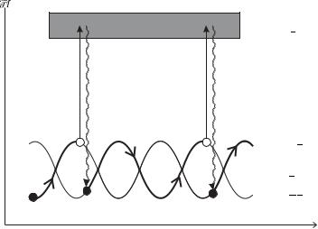
A particularly important mechanism by which atoms dissipate energy as they move through a standing wave is the Sisyphus e ect that was explained by Jean Dalibard and Claude Cohen-Tannoudji (1989), and this section follows the description given in that seminal paper. Steven Chu and co-workers also developed a model to explain sub-Doppler cooling based on the transfer of population between the di erent sub-levels of the ground configuration (optical pumping) as atoms move through the light field. This transfer of populations takes place on a time-scale τpump that can be much longer than the spontaneous lifetime (τpump 1/Γ). This longer time-scale gives better energy resolution than in a two-level atom and therefore allows cooling below the Doppler cooling limit, i.e. kBT /τpump < Γ/2. A specific example of this general argument is shown in Fig. 9.17, and the following section gives more details.
9.7.2Detailed description of Sisyphus cooling
Consider an atom that has a lower level with angular momentum J = 1/2 and an upper level with J = 3/2 that moves through a standing wave formed by two counter-propagating laser beams with orthogonal linear polarizations (e.g. along ex and ey ). The resultant polarization depends on the relative phase of the two laser beams and varies with position, as shown in Fig. 9.18(b). This polarization gradient causes the periodic modulation of the light shift of the states in the lower level. The strength of the interaction with the light depends on MJ and MJ in the lower and upper levels, respectively. To understand this in detail, consider
Fig. 9.17 The laser cooling mechanism in a standing wave with a spatiallyvarying polarization. The energy levels of the atom are perturbed by the light in a periodic way, so that the atoms travel up and down hills and valleys (maxima and minima) in the potential energy. Kinetic energy is lost when the atom absorbs laser light at the top of a hill and emits a spontaneous photon of higher frequency, so that it ends up in a valley. This has been called the Sisyphus e ect and can be made more probable than the reverse process, so that there is strong laser cooling. Thus atoms in a standing wave are cooled below the Doppler cooling limit (the lowest temperature achievable with scattering force alone).
Excited state
Ground state

9.7 The Sisyphus cooling technique 205
(a) |
Excited state: |
|
|
|
|
|
Ground state: |
|
(b) |
Linear |
Linear ... |
Linear |
(c)
(d)
Energy
Distance along standing wave, 
Light |
Light |
shift |
shift |
Light |
Light |
shift |
shift |
Distance along standing wave, 
Fig. 9.18 Details of the Sisyphus cooling mechanism. (a) The electric dipole transitions between two levels with angular momenta J = 1/2 and J = 3/2. The relative strength of each transition is indicated—this gives the relative intensity when the states in the upper level are equally populated (each state has the same radiative lifetime). (b) The polarization in a standing
wave formed by two laser beams that propagate along ez and −ez , and have orthogonal linear polarizations along ex and ey ,
√
respectively. The resultant electric field is circularly polarized (ex ± i ey ) / 2 at positions where the two counter-propagating beams have a phase di erence of ±π/2. The polarization changes from σ+ to σ− over a distance of ∆z = λ/4, and between these positions the light has elliptical or linear polarization. (c) The energies of the states at positions of σ− and σ+ polarization (the unperturbed energy of the lower level is shown as a dotted line). Absorption of the circularly-polarized light followed by spontaneous emission transfers the population into the state with lowest energy (largest light shift). (d) The light shift varies with position and the optical pumping process, outlined in (c), transfers atoms from the top of a hill to the bottom of a valley (as shown in Fig. 9.17); or at least this process in which atoms lose energy happens more often than the other way around.