11.1 Young’s double-slit experiment 247
the Sagnac e ect. These matter-wave experiments operate on the same principles as similar experiments with light because the atoms remain in the ground state and propagate as simple waves. It will be assumed that the reader understands the standard treatment of Fraunhofer di raction in optics (Brooker 2003) and key results will be quoted here rather than derived. After the discussion of the work with nano-fabricated slits and gratings, we shall look at the use of laser light to manipulate the atom’s momentum using methods closely related to laser cooling. These laser techniques make use of the atom’s internal energy levels—something that is not possible for electrons or neutrons.
11.1Young’s double-slit experiment
Young originally carried out his double-slit experiment to test the wave nature of light and his simple arrangement still finds practical use in measurements of the coherence of light.2 Figure 11.1 shows a typical experimental layout. Waves propagate from the source slit S through the two slits, Σ1 and Σ2, to a point P in the detection plane.3 The amplitude of the light at any point on the detection plane equals the sum of the electric field amplitudes that arrive at that point via slits Σ1 and Σ2. In any interference or di raction calculation the resultant amplitude at the final point is determined by summing the contributions from all possible paths taking account of the phase. For the double slits
2The double slits also form the basis of many theoretical discussions of fundamental issues in quantum mechanics, such as why we cannot know which slit the photon went through and still observe interference.
3Young’s fringes are not localised on this plane but can be seen throughout the far-field region.
(a)
Detector
(b)
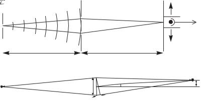
Fig. 11.1 (a) The apparatus for observing interference from double slits. The light di racted by the source slit propagates through the two slits Σ1 and Σ2 and onto the plane P. The interference fringes can be seen with the eye (with the aid of a magnifying eyepiece if necessary), but to further the analogy with atom optics experiments the apparatus is drawn with a detector such as a photodiode or photomultiplier. A narrow slit in front of the detector gives good spatial resolution; this slit and the detector scan across the fringes, as indicated. The light comes from a lamp, or laser; in a matter-wave experiment an atomic oven creates a beam of atoms collimated by the source slit (as shown in Fig. 11.2). (b) The di erence in the distance from Σ1 to P and from Σ2 to P is d sin θ, where d is the slit separation. The angle θ and the distance X in the detection plane are related by X = L tan θ. The transverse distances are drawn greatly exaggerated for clarity; for the typical conditions given in the text the fringes have an angular separation of 2 × 10⁻³ rad.
248 Atom interferometry
we define l1 as the distance from S to P via Σ1, and similarly l2 for the 4l1 = SΣ1 + Σ1P and l2 = SΣ2 + Σ2P. path through slit Σ2, as shown by the dotted lines in Fig. 11.1(b).4 Slits of the same size contribute equally to the total amplitude at a point on
the plane P: |
$e− |
|
|
+ e− |
& . |
2 |
EP E0 |
|
|
|
|
i2π 1 |
/λ |
|
i2π 2/λ |
(11.2) |
|
|
|
|
|
|
The intensity is proportional to the square of this amplitude, I |E| ,
|
so that |
|
φ |
. |
|
|
I = I0 cos2 |
(11.3) |
|
|
|
2 |
Here φ = 2π( 2 − 1)/λ is the phase di erence between the two arms and I0 is the maximum intensity. Bright fringes occur at positions in the detection plane where the contributions from the two paths interfere constructively; these correspond to φ = n2π, with n an integer, or equivalently
5Elementary treatments often assume that the slits are equidistant from the source (∆l = 0) so that the phase of the wave is the same at each slit (equivalent to having a plane wavefront before the slits). This assumption simplifies the algebra but it is not a necessary condition for Fraunhofer di raction with light, or with matter waves. (A more detailed description of the assumptions such as L d can be found in textbooks on optics, e.g. Brooker (2003).)
To find the spacing of the fringes in the plane of observation we define the coordinate X measured perpendicular to the long axis of the slits in the plane P. In terms of the small angle defined in Fig. 11.1(b) this becomes
A similar small angle approximation allows us to express the path length di erence in Fig. 11.1(b) as
2 − 1 = ∆l + d sin θ . |
(11.6) |
Here ∆l = SΣ1 − SΣ2 is the path di erence before the slits.5 The path length di erence from the two slits of separation d to P is d sin θ. The last three equations give the spacing of the fringes as
For an experiment with visible light of wavelength λ = 6 × 10⁻⁷ m, slits of separation d = 3 × 10⁻⁴ m and L = 1 m, the fringes have a spacing of ∆X = 2 mm and can be clearly seen by eye. The treatment so far assumes a small source slit at S that acts like a point source to illuminate the double slits coherently. The condition for this is that the double slits fall within the angular spread of the light di racted from the source slit (Brooker 2003). The di raction from a slit of width wS has an angular spread θdi λ/wS. Therefore coherent illumination of two slits at a distance L from this source slit requires L θdi d, or
|
wS |
λL |
. |
(11.8) |
|
|
|
|
d |
|
For L = |
0.1 m and the values of λ and d used previously, we find |
wS 2 × |
10−4 m. Such slits are made by standard techniques and we |
know that Young’s experiment with light is relatively straightforward to
11.2 A di raction grating for atoms 249
carry out in the laboratory. Experiments with short-wavelength matter waves require the smallest available structures with slits on the scale of 100 nm.
A double-slit experiment was carried out with a beam of helium atoms in the metastable 1s2s 3S1 level that lies 20 eV above the ground state (Carnal and Mlynek 1991). This matter-wave experiment had the same layout as that shown in Fig. 11.1, although with atoms the interferometer has to be set up inside a vacuum chamber. Exercise 11.2 goes through the application of the equations given in this section to the calculation of the slit widths required to observe interference fringes with He . Metastable helium is very suitable for this experiment, firstly because it has a fairly long λdB and secondly when metastable atoms hit a surface they release su cient energy to eject electrons; counting these charged particles allows the arrival of individual atoms to be detected with high e ciency. Further discussion of double-slit experiments can be found in the quantum mechanics book by Rae (1992); he uses a neutron interference experiment as an example of wave–particle duality.
11.2A di raction grating for atoms
Figure 11.2 shows an apparatus with a highly-collimated atom beam of sodium incident upon a transmission grating. The experimenters used a remarkable grating with slits only 50 nm wide, spaced 100 nm apart—equal widths of the bars and the gaps between them. Etching these very thin bars and their delicate support structure represents the state of the art in nano-fabrication. Figure 11.2(b) shows the di raction pattern obtained with a mixture of sodium atoms and molecules, and Fig. 11.2(c) shows the di raction of a beam of sodium molecules. The di raction peaks of Na2 have about half the spacing of those for the Na atoms, as expected from the de Broglie relation for particles of twice the mass (for similar velocities).
Researchers recently exploited this property of these special gratings to make the first experimental observation of the very weakly-bound state of two helium atoms (Sch¨ollkopf and Toennies 1994). Other methods of detection dissociate the very tenuously-bound He2 molecule. The gratings work well with helium and atomic beams of inert gases, since they do not clog the slits in the same way as sodium. However, despite the practical di culties of working with these very fragile structures,
arecent experiment used a grating to di ract C60 molecules—so-called Buckyballs (Arndt et al. 1999, Nairz et al. 2003). This demonstration of the wave-like nature of such massive particles prompts the following question: ‘What is the largest object for which such quantum interference can be observed?’6 This question relates to Schr¨odinger’s wellknown example of a cat that may be in a superposition of two states (‘alive’ and ‘dead’). To observe interference an object must exist in
asuperposition of the two states: |1 in which it goes through slit Σ1 and |2 the state where it goes through slit Σ2. Nothing within standard
6This means quantum e ects in the motion, or external degrees of freedom, and not quantisation of the internal energy levels.
250 |
Atom interferometry |
|
(a) |
|
Detector |
|
Supersonic beam |
Grating |
|
|
|
of atoms and molecules |
|
|
Source |
|
Carrier 
gas
(b)
104
Counts/second
103
−1000 |
−500 |
0 |
500 |
1000 − |
|
|
|
|
|
|
|
|
|
|
|
1000 |
−500 |
0 |
500 |
1000 |
|
Detector position ( m) |
|
|
|
|
|
Detector position ( |
m) |
|
|
|
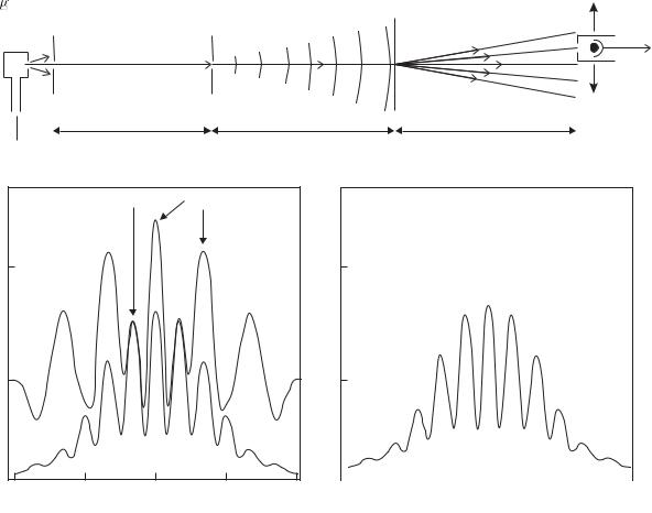
Fig. 11.2 (a) Di raction of a collimated atomic beam by a grating. To observe the di raction of matter waves from the grating the source slit must be su ciently narrow to make the matter waves coherent across several of the slits in the grating. This is the same requirement as described in the previous section for Young’s double slits, and Exercise 11.1 looks at the relation of the pattern with multiple slits to that observed with just two slits. For the grating there is an additional requirement that the angular spread of the incident beam must be less than the angle between the di racted orders, otherwise they cannot be distinguished. In this apparatus the slit widths were about 20 µm, the slits in the nano-fabricated grating had a spacing of 100 nm and all the distances LC, L and L were about 1 m. (b) The di raction of a collimated beam of sodium atoms and molecules by the grating. (c) The di raction pattern for a beam that contains only Na2 molecules (this pattern is also shown as a dotted curve in (b)). The peaks for the molecules have half the spacing of those for the atoms as expected for twice the mass—the atoms and molecules have almost the same velocity in the supersonic flow because they are both carried along in a stream of krypton gas that flows through the heated oven containing sodium metal. This carrier gas gives a supersonic beam with a much lower velocity spread ∆v/v 0.03 than would be obtained from an e usive source of thermal atoms. The sodium atoms were removed from the beam by the resonant radiation pressure from a laser beam (not shown) perpendicular to the supersonic beam—scattering three or more photons was su cient to deflect atoms out of the beam. From Chapman et al. (1995). Copyright 1995 by the American Physical Society.
11.4 Measurement of rotation 251
quantum mechanics tells us that we cannot put something as large as a cat into a quantum superposition, if it is completely isolated from external perturbations. However, the heaviest object that can be used in a practical double-slit experiment in the foreseeable future is far lighter than a cat, but considerably heavier than what has been achieved so far. Continued work on matter-wave interference of larger and larger objects will be of great interest since it probes the boundary between quantum and classical physics.
11.3The three-grating interferometer
Figure 11.3 shows an arrangement of three di raction gratings a distance L apart. A highly-collimated beam of sodium atoms propagates through this three-grating interferometer onto a detector for atoms.7 Di raction at the first grating G1 splits the beam—only the zerothand first-order di raction orders (0 and ±1 orders) have been drawn for simplicity. The second grating G2 gives di raction through the same angles as G1, so that some of the paths meet up at the plane of the third grating G3, e.g. the 0 and +1 orders from G1 are both di racted by G2 to form the parallelogram ABPC, as shown in Fig. 11.3(a). The detector records the flux of atoms along one of the possible output directions coming from P. This arrangement closely resembles a Mach–Zehnder interferometer for light, with a smaller angle between the two arms because of the achievable grating spacing. For two-beam interference the signal has the same form as eqn 11.3. In these interferometers the sum of the fluxes of the atoms, or light, in the two possible output directions equals a constant, i.e. when a certain phase di erence between the arms of the interferometer gives destructive interference at the detector then the flux in the other output direction has a maximum.
7The detector for sodium has a hot wire, heated by a current flowing through it, that runs parallel to the slits. The sodium atoms ionize when they hit the hot surface of the wire and the ejected electrons create a measurable current.
11.4Measurement of rotation
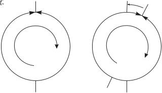
The Mach–Zehnder interferometer for matter waves shown in Fig. 11.3 measures rotation precisely, as explained in this section.8 To calculate the phase shift caused by rotation in a simple way we represent the interferometer as a circular loop of radius R, as in Fig. 11.4. The wave travelling at speed v from the point S takes a time t = πR/v to propagate around either arm of the interferometer to the point P diametrically opposite S. During this time the system rotates through an angle Ωt, where Ω is the angular frequency of rotation about an axis perpendicular to the plane of the interferometer. Thus the wave going one way round the loop has to travel ∆l = 2ΩRt further than the wave in the other arm of the interferometer. This corresponds to ∆l/λdB extra wavelengths, or a phase shift of
∆φ = |
2π |
× 2ΩR × |
πR |
(11.9) |
|
|
. |
λdB |
v |
8For light a di erent configuration called a Sagnac interferometer is generally used to measure rotation but the principles are similar.
252 Atom interferometry |
|
|
|
(a) |
G1 |
Order of |
G2 |
G3 |
|
|
|
|
|
Collimated beam |
diffraction |
|
Detector |
|
|
|
|
of atoms |
|
|
|
(b)
Detector
S
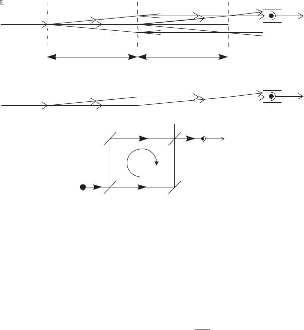
Fig. 11.3 (a) An interferometer formed by three di raction gratings spaced by a distance L along the atomic beam. A collimated beam of atoms is produced, as shown in Fig. 11.2. Waves di racted at the first grating G1 split again at G2, so that some of the paths meet at G3. Only the 0 and ±1 di raction orders are shown and to further simplify the diagram some of the possible paths between G2 and G3 have not been drawn completely. Contributions to the amplitude at P arrive from A, via either B or C. The detector must be su ciently far from G3 that it picks up only one of two possible output directions. (The parallelogram ABPC is just one of many closed loops formed by the three gratings; some others are indicated by dotted lines. With the detector at the position shown, the three gratings act as a Mach–Zehnder interferometer, as shown in (b). The di raction gratings behave both as beam splitters and as deflectors (mirrors) for the matter waves (for small angles). (c) A Mach–Zehnder interferometer for light—the optical system equivalent to the three-grating interferometer. The incident wave hits beam splitter BS1 and the reflected and transmitted amplitudes reflect o mirrors M1 and M2, respectively, so that their paths meet again at BS2. Interference between the two paths leads to a detected intensity ID = 12 I0{1 + cos(φ + ∆φ)} (cf. eqn 11.3). The phase φ that arises from path length di erences and phase shifts on reflection at the mirrors is assumed to be fixed and ∆φ represents the extra phase that is measured; e.g. for an interferometer that rotates at angular frequency Ω about an axis perpendicular to the plane of the instrument ∆φ Ω, so the instrument measures rotation, as shown in Section 11.4.
The loop has area A = πR2, so that
∆φ = |
4π |
× ΩA . |
(11.10) |
λdBv |
A more rigorous derivation, by integration around a closed path, shows that this equation applies for an arbitrary shape, e.g. the square interferometer of Fig. 11.3(c). Comparison of this phase shift for matter waves of velocity v with that for light ∆φlight, for an interferometer of the same
11.5 The di raction of atoms by light 253
 P
P
|
|
Fig. 11.4 (a) A simplified diagram |
|
|
of an interferometer where the waves |
|
|
propagate from S to P. (b) Rotation at |
|
|
angular frequency Ω about an axis per- |
|
|
pendicular to the plane of the interfer- |
|
|
ometer makes one path Ωt longer and |
|
|
the other shorter by the same amount, |
|
|
where t is the time taken for a wave to |
S |
S |
travel from S to P. This leads to the |
|
|
phase shift in eqn 11.10. |
area A, shows that
∆φ = |
λc |
|
M c2 |
|
|
× ∆φlight = |
|
× ∆φlight . |
(11.11) |
λdBv |
ω |
The ratio equals the rest mass of the atom divided by the energy of each photon and has a value of ∆φ/∆φlight 1010 for sodium atoms and visible light. This huge ratio suggests that matter-wave interferometers have a great advantage, but at the present time they only achieve comparable results to conventional interferometers with light. Conventional interferometers with light make up the ground by:
(a)having much larger areas, i.e. a distance between the arms of metres instead of a fraction of a millimetre achieved for matter waves;
(b)the light goes around the loop many times;9
(c)lasers give a much higher flux than the flux of atoms in a typical atomic beam. For example, in the scheme shown in Fig. 11.2 only a small fraction of the atoms emitted from the source end up in the highly-collimated atomic beam; as a source of matter waves the atomic oven is analogous to an incandescent tungsten light bulb rather than a laser.10
9Laser gyros use high-reflectivity mirrors or optical fibres.
10The atom interferometer based on Raman transitions (described in Section 11.5.1) does not require such a highly-collimated atomic beam, and that technique has achieved precise measurements of rotation.
11.5The di raction of atoms by light
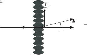
A standing wave of light di racts matter waves, as illustrated in Fig. 11.5. This corresponds to a role reversal as compared to optics in which matter, in the form of a conventional grating, di racts light. This section explains how this light field created simply by the retro-reflection of a laser beam from a mirror is used in atom optics. The interaction of atoms with a standing wave leads to a periodic modulation of the atomic energy levels by an amount proportional to the intensity of the light, as explained in Section 9.6.11 The light shift of the atomic energy levels in the standing wave introduces a phase modulation of the matter waves. An atomic wavepacket ψ(x, z, t) becomes ψ(x, z, t) ei∆φ(x) immediately after passing through the standing wave; it is assumed that
11The laser has a frequency ω su - ciently far from the atom’s transition frequency ω0 that spontaneous emission has a negligible e ect, yet close enough for the atoms to have a significant interaction with the light.
11.5 The di raction of atoms by light 255
receive a transverse kick from 2n photons, as illustrated in Fig. 11.5, e.g. first order arises from absorption from one of the counter-propagating beams and stimulated emission into the other beam. This coherent process, with no spontaneous emission, has some similarities with the Raman transition shown in Fig. 11.6.13
13Scattering in a standing wave changes the atomic momentum (external state) but not the internal state.
11.5.1Interferometry with Raman transitions
The description of the di raction of two-level atoms by a standing wave, in the previous section, as a coherent scattering process that imparts twice the photon momentum 2h/λ, or multiples thereof, to the atom has links with the very powerful method for manipulating the atom’s momentum by Raman transitions shown in Fig. 11.6. Two laser beams at frequencies ωL1 and ωL2 drive a coherent Raman transition between states |1 and |2 when
(ωL1 − ωL2) = E2 − E1 . |
(11.13) |
No population goes into the intermediate state |i in this coherent transition because neither of the two beams excites a single-photon transition (see Appendix E). The Raman transition couples states |1 and |2 and drives Rabi oscillations between them, e.g. when the atom starts in either |1 or |2 , a π/2-pulse creates a superposition of |1 and |2 with equal amplitudes. Raman laser beams propagating in opposite directions (as in Fig. 11.6) change the atom’s momentum during the transition.14 The absorption of a photon of wavevector k1 and the stimulated emission of one in the opposite direction k2 −k1 gives the atom two recoil kicks in the same direction. This process couples the state |1, p to |2, p + 2 k . The bra(c)ket notation denotes the |internal state, momentum of the atoms. The Raman resonance condition in eqn 11.13 depends sensitively on the atom’s velocity v for counter-propagating beams and this provides the basis for the Raman cooling of atoms (Section 9.8). For interferometry this velocity selectivity is a complicating factor and we shall assume that the Raman pulses are su ciently short15 to drive transitions over the whole range of velocity components along the laser beam.
Figure 11.7 shows a complete Raman interferometer where the atoms start in |1, p and travel through three Raman interaction regions. In
14Raman laser beams travelling in the same direction have the same e ect as direct coupling between |1 and |2 by microwaves.
15According to the condition in eqn 9.58.
Fig. 11.6 A Raman transition with two laser beams of frequencies ωL1 and ωL2 that propagate in opposite directions. Equation 11.13 gives the resonance condition, ignoring the e ects of the atom’s motion (Doppler shift). The Raman process couples |1, p and |2, p + 2 k so that an atom in a Raman interferometer has a wavefunction of the form ψ = A|1, p + B|2, p + 2 k (usually with either B = 0 or A = 0 initially).