

ADS8325
www.ti.com
SBAS226C –MARCH 2002 –REVISED AUGUST 2007
ELECTRICAL CHARACTERISTICS: VDD = +2.7V
Over recommended operating free-air temperature at –40°C to +85°C, VREF = +2.5V, –IN = GND, fSAMPLE = 100kHz, and fCLK = 24 × fSAMPLE, unless otherwise noted.
|
|
|
|
ADS8325I |
|
|
ADS8325IB |
|
|
PARAMETER |
|
TEST CONDITIONS |
MIN |
TYP |
MAX |
MIN |
TYP |
MAX |
UNIT |
ANALOG INPUT |
|
|
|
|
|
|
|
|
|
Full-scale range |
FSR |
+IN – (–IN) |
0 |
|
VREF |
0 |
|
VREF |
V |
Operating common-mode signal |
|
|
–0.3 |
|
0.5 |
–0.3 |
|
0.5 |
V |
Input resistance |
|
–IN = GND |
|
5 |
|
|
5 |
|
GΩ |
Input capacitance |
|
–IN = GND, during sampling |
|
45 |
|
|
45 |
|
pF |
Input leakage current |
|
–IN = GND |
|
±50 |
|
|
±50 |
|
nA |
Differential input capacitance |
|
+IN to –IN, during sampling |
|
20 |
|
|
20 |
|
pF |
Full-power bandwidth |
FSBW |
FS sinewave, SINAD = –3 dB |
|
4 |
|
|
4 |
|
kHz |
DC ACCURACY |
|
|
|
|
|
|
|
|
|
Resolution |
|
|
16 |
|
|
16 |
|
|
Bits |
No missing code |
NMC |
|
14 |
|
|
15 |
|
|
Bits |
Integral linearity error |
INL |
|
|
±3 |
±6 |
|
±1.5 |
±4 |
LSB |
Offset error |
VOS |
|
|
±0.75 |
±1.5 |
|
±0.5 |
±1 |
mV |
Offset error drift |
TCVOS |
|
|
±3 |
|
|
±3 |
|
ppm/°C |
Gain error |
GERR |
|
|
±33 |
|
|
±16 |
|
LSB |
Gain error drift |
TCGERR |
|
|
±0.3 |
|
|
±0.3 |
|
ppm/°C |
Noise |
|
|
|
20 |
|
|
20 |
|
μVRMS |
Power-supply rejection |
|
2.7V ≤ VDD ≤ 3.6V |
|
7 |
|
|
7 |
|
LSB |
SAMPLING DYNAMICS |
|
|
|
|
|
|
|
|
|
Conversion time |
tCONV |
24kHz < fCLK ≤ 2.4MHz |
6.667 |
|
666.7 |
6.667 |
|
666.7 |
μs |
Acquisition time |
tAQ |
fCLK = 2.4MHz |
1.875 |
|
|
1.875 |
|
|
μs |
Throughput rate |
|
|
|
|
100 |
|
|
100 |
kSPS |
Clock frequency |
|
|
0.024 |
|
2.4 |
0.024 |
|
2.4 |
MHz |
AC ACCURACY |
|
|
|
|
|
|
|
|
|
Total harmonic distortion |
THD |
2.5VPP sinewave, at 1kHz |
|
–94 |
|
|
–94 |
|
dB |
Spurious-free dynamic range |
SFDR |
2.5VPP sinewave, at 1kHz |
|
–96 |
|
|
–96 |
|
dB |
Signal-to-noise ratio |
SNR |
|
|
–85 |
|
|
–86 |
|
dB |
Signal-to-noise + distortion |
SINAD |
2.5VPP sinewave, at 1kHz |
|
–85 |
|
|
–85.5 |
|
dB |
Effective number of bits |
ENOB |
|
|
13.8 |
|
|
13.9 |
|
Bits |
VOLTAGE REFERENCE INPUT |
|
|
|
|
|
|
|
|
|
Reference voltage |
|
|
2.5 |
|
VDD + 0.3 |
2.5 |
|
VDD + 0.3 |
V |
Reference input resistance |
|
CS = GND, fSAMPLE = 0Hz |
|
5 |
|
|
5 |
|
kΩ |
|
CS = VDD |
|
5 |
|
|
5 |
|
GΩ |
|
|
|
|
|
|
|
||||
Reference input capacitance |
|
|
|
20 |
|
|
20 |
|
pF |
Reference input current |
|
|
|
0.5 |
0.75 |
|
0.5 |
0.75 |
mA |
|
CS = VDD |
|
0.1 |
|
|
0.1 |
|
μA |
|
|
|
|
|
|
|
||||
DIGITAL INPUTS(1) |
|
|
|
|
|
|
|
|
|
Logic family |
|
|
|
LVCMOS |
|
|
LVCMOS |
|
|
High-level input voltage |
VIH |
VDD = 3.6V |
2 |
|
VDD + 0.3 |
2 |
|
VDD + 0.3 |
V |
Low-level input voltage |
VIL |
VDD = 2.7V |
–0.3 |
|
0.8 |
–0.3 |
|
0.8 |
V |
Input current |
IIN |
VI = VDD or GND |
|
|
±50 |
|
|
±50 |
nA |
Input capacitance |
CI |
|
|
5 |
|
|
5 |
|
pF |
(1)Applies for 3.0V nominal supply: VDD (min) = 2.7V and VDD (max) = 3.6V.
Copyright © 2002–2007, Texas Instruments Incorporated |
Submit Documentation Feedback |
5 |
Product Folder Link(s): ADS8325
ADS8325
www.ti.com
SBAS226C –MARCH 2002 –REVISED AUGUST 2007
ELECTRICAL CHARACTERISTICS: VDD = +2.7V (continued)
Over recommended operating free-air temperature at –40°C to +85°C, VREF = +2.5V, –IN = GND, fSAMPLE = 100kHz, and fCLK = 24 × fSAMPLE, unless otherwise noted.
|
|
|
ADS8325I |
|
|
ADS8325IB |
|
|
PARAMETER |
TEST CONDITIONS |
MIN |
TYP |
MAX |
MIN |
TYP |
MAX |
UNIT |
DIGITAL OUTPUTS(2) |
|
|
|
|
|
|
|
|
 Logic family
High-level output voltage
 Low-level output voltage
High-impedance-state output current
 Output capacitance
  Load capacitance
  Data format
|
|
LVCMOS |
|
LVCMOS |
|
|
VOH |
VDD = 2.7V, IOH = –100μA |
VDD – 0.2 |
|
VDD – 0.2 |
|
V |
VOL |
VDD = 2.7V, IOL = 100μA |
|
0.2 |
|
0.2 |
V |
IOZ |
CS = VDD, VI = VDD or GND |
|
±50 |
±50 |
±50 |
nA |
CO |
|
5 |
|
5 |
|
pF |
CL |
|
|
30 |
|
30 |
pF |
|
|
Straight Binary |
|
Straight Binary |
|
|
(2)Applies for 3.0V nominal supply: VDD (min) = 2.7V and VDD (max) = 3.6V.
ELECTRICAL CHARACTERISTICS
Over recommended operating free-air temperature at –40°C to +85°C, VREF = VDD, –IN = GND, fSAMPLE = 100kHz, and fCLK = 24 × fSAMPLE, unless otherwise noted.
|
|
|
|
ADS8325I |
|
|
ADS8325IB |
|
UNIT |
PARAMETER |
|
TEST CONDITIONS |
MIN |
TYP |
MAX |
MIN |
TYP |
MAX |
|
|
|
||||||||
POWER-SUPPLY REQUIREMENTS |
|
|
|
|
|
|
|
|
|
Power supply |
VDD |
Low-voltage levels |
2.7 |
|
3.6 |
2.7 |
|
3.6 |
V |
5V logic levels |
4.5 |
|
5.5 |
4.5 |
|
5.5 |
V |
||
Operating supply current |
IDD |
VDD = 3V |
|
0.75 |
1.5 |
|
0.75 |
1.5 |
mA |
V = 5V |
|
0.9 |
1.5 |
|
0.9 |
1.5 |
mA |
||
|
|
DD |
|
|
|
|
|
|
|
Power-down supply current |
(IDD |
VDD = 3V |
|
0.1 |
|
|
0.1 |
|
μA |
VDD = 5V |
|
0.2 |
|
|
0.2 |
|
μA |
||
Power dissipation |
|
VDD = 3V |
|
2.25 |
4.5 |
|
2.25 |
4.5 |
mW |
|
VDD = 5V |
|
4.5 |
7.5 |
|
4.5 |
7.5 |
mW |
|
|
|
|
|
||||||
Power dissipation in power-down |
|
VDD = 3V, CS = VDD |
|
0.3 |
|
|
0.3 |
|
μW |
|
VDD = 5V, CS = VDD |
|
0.6 |
|
|
0.6 |
|
μW |
|
|
|
|
|
|
|
6 |
Submit Documentation Feedback |
Copyright © 2002–2007, Texas Instruments Incorporated |
Product Folder Link(s): ADS8325
ADS8325
www.ti.com
SBAS226C –MARCH 2002 –REVISED AUGUST 2007
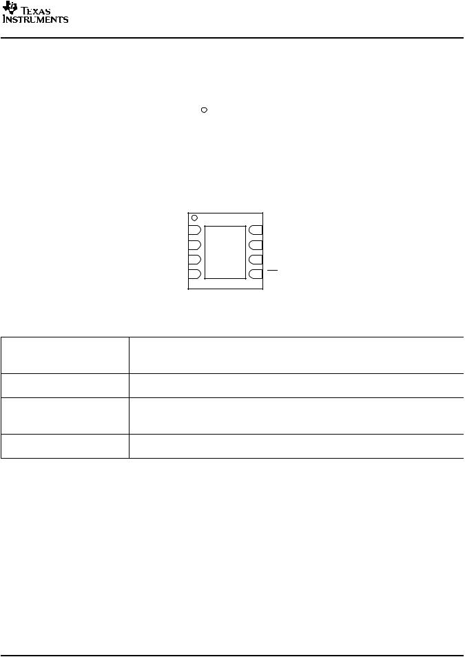
PIN CONFIGURATIONS
DGK PACKAGE
MSOP
(TOP VIEW)
|
|
|
|
+VDD |
||
REF |
1 |
|
8 |
|||
|
|
|
|
DCLOCK |
||
|
|
|
|
|||
+IN |
2 |
|
7 |
|||
|
|
ADS8325 |
|
|
|
|
|
|
|
|
|
|
|
−IN |
3 |
|
6 |
|
DOUT |
|
|
|
|
|
|
|
|
GND |
4 |
|
5 |
CS/SHDN |
||
|
|
|
|
|
|
|
|
|
|
|
|
|
|
DRB PACKAGE(1)
SON
(TOP VIEW)
REF |
1 |
8 |
+VDD |
+IN |
2 |
7 |
DCLOCK |
|
|
ADS8325 |
|
−IN |
3 |
6 |
DOUT |
GND |
4 |
(Thermal Pad) 5 |
CS/SHDN |
(1)The thermal pad is internally connected to the substrate. This pad can be connected to the analog ground or left floating. Keep the thermal pad separate from the digital ground, if possible.
|
|
|
PIN ASSIGNMENTS |
PIN |
|
|
|
NAME |
NO. |
I/O(1) |
DESCRIPTION |
REF |
1 |
AI |
Reference Input |
+IN |
2 |
AI |
Noninverting Input |
–IN |
3 |
AI |
Inverting Analog Input |
GND |
4 |
P |
Ground |
CS/SHDN |
5 |
DI |
Chip select when low; Shutdown mode when high. |
DOUT |
6 |
DO |
The serial output data word. |
DCLOCK |
7 |
DI |
Data clock synchronizes the serial data transfer and determines conversion speed. |
+VDD |
8 |
P |
Power supply |
(1)AI is Analog Input, DI is Digital Input, DO is Digital Output, and P is Power-Supply Connection.
Copyright © 2002–2007, Texas Instruments Incorporated |
Submit Documentation Feedback |
7 |
Product Folder Link(s): ADS8325
ADS8325
www.ti.com
SBAS226C –MARCH 2002 –REVISED AUGUST 2007
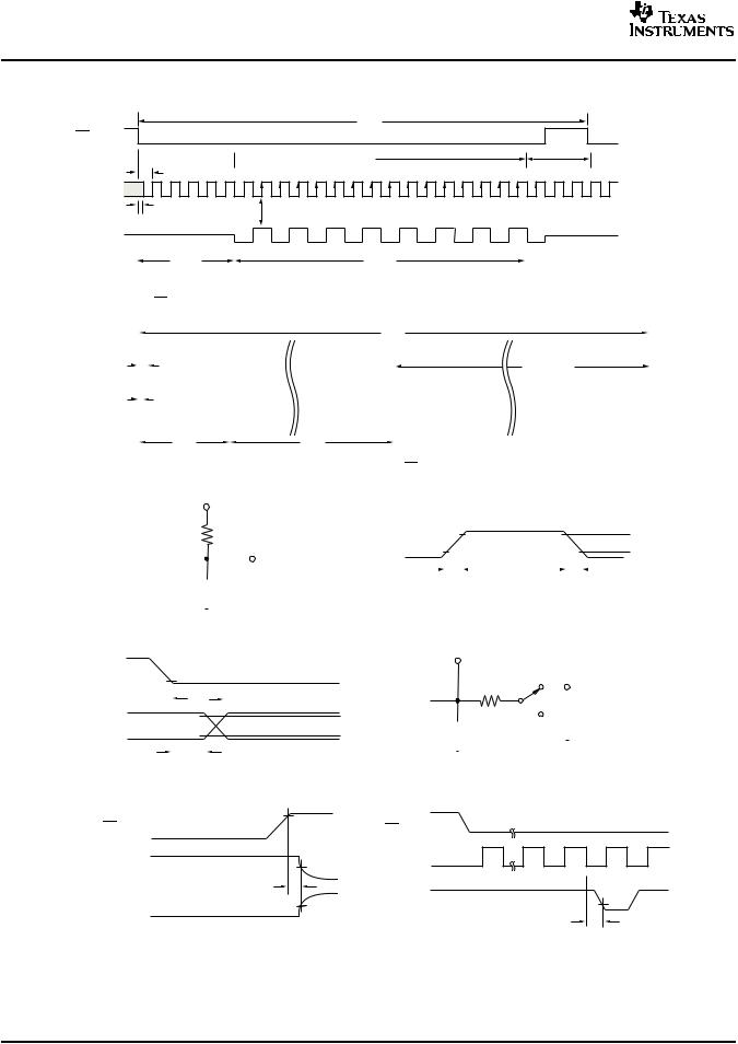
TIMING INFORMATION
tCYC
CS/SHDN
Power Down
 Sample
 Conversion
tSUCS
DCLOCK
tCSD |
Use positive clock edge for data transfer |
|
DOUT |
Hi-Z |
0 B15 B14 B13 B12 B11 B10 |
B9 B8 B7 B6 B5 B4 B3 B2 B1 B0(1) |
Hi-Z |
|
|
|
(MSB) |
(LSB) |
|
|
|
tSMPL |
|
|
|
|
|
|
tCONV |
|
|
|
NOTE: (1) A minimum of 22 clock cycles are required for 16-bit conversion; 24 clock cycles are shown.
If CS remains low at the end of conversion, a new data stream is shifted out with LSB-first data followed by zeroes indefinitely.
|
|
|
|
|
|
|
|
|
|
|
|
|
|
|
|
|
|
|
|
|
|
|
|
|
|
|
|
|
|
|
tCYC |
|
|
|
|
|
|
|
|
|
|
|
|
|
|
|
|
|
|
|
|
|
|
||||
|
|
|
|
|
|
|
|
|
|
|
|
|
|
|
|
|
|
|
|
|
|
|
|
|
|
|
|
|
|
|
|
|
|
|
|
|
|
|
|
|
|
|
|
|
|
|
|
|
|
|
|
|
|
|
|
|
|
CS/SHDN |
|
|
|
|
|
|
|
|
|
|
|
|
|
|
|
|
|
|
|
|
|
|
|
|
|
|
|
|
|
|
|
|
|
|
|
|
|
|
|
|
|
|
|
|
|
|
|
|
|
|
|
|
|
|
|
||
|
|
|
|
|
|
|
|
|
|
|
|
|
|
|
|
|
|
|
|
|
|
|
|
|
|
|
|
|
|
|
|
|
|
|
|
|
|
|
|
|
|
|
|
|
|
|
|
|
|
|
|
|
|
|
|
|
|
|
|
|
|
|
|
tSUCS |
|
|
|
|
|
|
|
|
|
|
|
|
|
|
|
|
|
|
|
|
|
|
|
|
|
|
Power Down |
|
|||||||||||||||||||||||
|
|
|
|
|
|
|
|
|
|
|
|
|
|
|
|
|
|
|
|
|
|
|
|
|
|
|
|
|
|
|
|
|
|||||||||||||||||||||||||
|
|
|
|
|
|
|
|
|
|
|
|
|
|
|
|
|
|
|
|
|
|
|
|
|
|
|
|
|
|
|
|
|
|
|
|
|
|
|
|
|
|
|
|
|
|
|
|
|
|
|
|
|
|
|
|
|
|
DCLOCK |
|
|
|
|
|
|
|
|
|
|
|
|
|
|
|
|
|
|
|
|
|
|
|
|
|
|
|
|
|
|
|
|
|
|
|
|
|
|
|
|
|
|
|
|
|
|
|
|
|
|
|
|
|
|
|
||
|
|
|
|
|
|
|
|
|
|
|
|
|
|
|
|
|
|
|
|
|
|
|
|
|
|
|
|
|
|
|
|
|
|
|
|
|
|
|
|
|
|
|
|
|
|
|
|
|
|
|
|
|
|
|
|
|
|
|
|
|
|
|
tCSD |
|
|
|
|
|
|
|
|
|
|
|
|
|
|
|
|
|
|
|
|
|
|
|
|
|
|
|
|
|
|
|
|
|
|
|
|
|
|
|
|
||||||||||||
|
|
|
|
|
|
|
|
|
|
|
|
|
|
|
|
|
|
|
|
|
|
|
|
|
|
|
|
|
|
|
|
|
|
|
|
|
|
|
|
|
|
|
|||||||||||||||
|
DOUT |
|
|
|
Hi-Z |
B15 |
B14 |
B6 |
B5 |
B4 |
B3 |
B2 |
B1 |
B0 B1 |
B2 |
B3 |
B4 |
B5 |
B0 |
B11 |
B12 |
B13 |
B14 |
(2) |
Hi-Z |
|
|||||||||||||||||||||||||||||||
|
|
|
|
|
|
|
|
|
|
|
|
|
0 |
B15 |
|
|
|||||||||||||||||||||||||||||||||||||||||
|
|
|
|
|
|
|
|
|
|
|
|
|
|
|
|
|
|
|
|
|
|
|
|
|
|
|
|
|
|
|
|
|
|
|
|
|
|
|
|
|
|
|
|
|
|
|
|
|
|
|
|
|
|
|
|
|
|
|
|
|
|
|
|
|
|
tSMPL |
|
(MSB) |
|
tCONV |
(LSB) |
|
|
|
|
|
|
|
|
|
|
|
|
|
|
|
|
|
(MSB) |
|
|||||||||||||||||||||||||
|
|
|
|
|
|
|
|
|
|
|
|
|
|
|
|
|
|
|
|
|
|
|
|
|
|
|
|
|
|
|
|
|
|
|
|
|
|
|
|
|
|||||||||||||||||
|
|
|
|
|
|
|
|
|
|
|
|
|
|
|
|
|
|
|
|
|
|
|
|
|
|
|
|
|
|
|
|
|
|
|
|
|
|
|
|
|
|
|
|
|
|
|
|
|
|
|
|
|
|
|
|
|
|
NOTE: (2) After completing the data transfer, if further clocks are applied with CS low, the A/D converter will output zeroes indefinitely.
|
|
|
1.4V |
|
|
|
|
|
|
|
|
|
|
|
|
|
|
|
|
|
|
|
|
|
|
|
|
|
|
|
|
|
|||||
|
|
|
|
|
|
|
|
|
3kΩ |
|
|
|
|
|
|
|
|
|
|
|
|
|
|
|
|
90% |
|||||||||||
|
|
|
|
|
|
|
|
|
|
|
|
|
|
|
|
|
|
|
|
|
|
|
|
||||||||||||||
|
|
|
|
|
|
|
|
|
|
|
|||||||||||||||||||||||||||
|
|
|
|
|
|
|
|
|
|
|
|
DOUT |
|
|
|
|
|
|
|
|
|
|
|
|
|
|
|
|
|
||||||||
|
DOUT |
|
|
|
|
|
|
|
|
|
Test Point |
|
|
|
|
|
|
|
|
|
|
|
|
|
|
|
|
|
|
|
|
|
10% |
||||
|
|
|
|
|
|
|
|
|
|
|
|
|
|
|
|
|
|
|
|
|
|
|
|
|
|
|
|
|
|
|
|||||||
|
|
|
|
|
|
|
|
|
|
|
|
|
|
|
|
|
|
|
|
|
|
|
|
|
|
|
|
||||||||||
|
|
|
|
|
|
|
|
|
|
|
|
||||||||||||||||||||||||||
|
|
|
|
|
|
|
|
|
|
|
|
tr |
|
|
|
|
|
|
|
|
|
|
|
|
|
|
|
|
|
|
|
|
|
|
|
|
tf |
|
|
|
|
|
|
|
|
|
|
|
|
|
|
|
|
|
|
|
|
|
|
|
|
|
|
|
|
|
|
|
|
|
|
||||
|
|
|
|
|
|
|
|
|
100pF |
|
|
|
|
|
|
|
|
|
|
|
|
|
|
|
|
|
|
|
|
|
|
|
|||||
|
|
|
|
|
|
|
|
|
CLOAD |
|
|
||||||||||||||||||||||||||
|
|
|
|
|
|
|
|
|
|
|
|
Voltage Waveforms for DOUT Rise and Fall Times, tr, tf |
|||||||||||||||||||||||||
|
|
|
|
|
|
|
|
|
|||||||||||||||||||||||||||||
|
Load Circuit for tdDO, tr, and tf |
|
|
||||||||||||||||||||||||||||||||||
|
|
|
|
|
|
|
|
|
|
|
|
|
Test Point |
|
|
||||||||||||||||||||||
|
|
|
|
|
|
|
|
|
|
|
|
|
|
|
|
|
|
|
|
|
|
|
|
|
|
|
|
|
|
|
|
|
|
|
|
|
|
DCLOCK |
|
|
|
|
|
|
|
|
|
|
|
|
|
|
|
|
|
|
|
|
|
|
|
|
VDD |
|
|
||||||||||
|
|
|
|
|
|
|
|
|
|
|
|
|
|
|
|
|
|
|
|
|
|
|
|
|
|
|
|
|
|||||||||
|
|
|
tdDO |
|
|
|
DOUT |
|
|
|
|
|
|
|
|
|
|
3kΩ |
|
|
tdis Waveform 2, ten |
||||||||||||||||
|
|
|
|
|
|
|
|
|
|
|
|
|
|
|
|
|
|||||||||||||||||||||
|
|
|
|
|
|
|
|
|
|
|
|
|
|
|
|
|
|
|
|
|
|
|
|
|
|
|
|
|
tdis Waveform 1 |
||||||||
|
|
|
|
|
|
|
|
|
|
|
|
|
|
|
|
|
|
|
|
|
|
|
|
|
|
|
|
|
|
|
|
|
|
|
|
||
DOUT |
|
|
|
|
|
|
|
|
|
|
|
|
|
|
|
|
|
|
|
100pF |
|
||||||||||||||||
|
|
|
|
|
|
|
|
|
|
|
|
|
|
|
|
|
|
|
|
|
|||||||||||||||||
|
|
|
|
|
|
|
|
|
|
|
|
|
|
|
|
|
|
|
CLOAD |
|
|
|
|
|
|
|
|
|
|
|
|||||||
|
thDO |
|
|
|
|
|
|
|
|
|
|
|
|
|
|
|
|
|
|
|
|
|
|
|
|
|
|
|
|||||||||
|
|
|
|
|
|
|
|
|
|
|
|
|
|
|
|
|
|
|
|
|
Load Circuit for tdis and ten |
|
|
||||||||||||||
|
|
|
|
|
|
|
|
|
|
|
|
|
|
|
|
|
|
|
|
|
|
|
|||||||||||||||
|
|
|
|
|
|
|
|
|
|
|
|
|
|
|
|
|
|
|
|
|
|
|
|
|
|||||||||||||
|
Voltage Waveforms for DOUT Delay Times, tdDO |
|
|
||||||||||||||||||||||||||||||||||
CS/SHDN |
90% |
CS/SHDN |
|
|
|
|
|
|
|
|
|||
|
|
|
|
|
|
|
DOUT |
90% |
DCLOCK |
1 |
4 |
5 |
|
Waveform 1(3) |
|
|
|
|
||
|
|
|
|
|
||
|
|
tdis |
|
|
|
|
D |
OUT |
10% |
DOUT |
|
|
B15 |
Waveform 2(4) |
|
|
|
|
||
|
|
|
|
ten |
||
|
|
|
|
|
|
|
|
|
Voltage Waveforms for tdis |
|
|
Voltage Waveforms for ten |
|
|
|
|
|
|
||
NOTES: (3) Waveform 1 is for an output with internal conditions such that |
|
|
|
|
||
the output is high unless disabled by the output control. |
|
|
|
|
||
(4) Waveform 2 is for an output with internal conditions such that |
|
|
|
|
||
the output is low unless disabled by the output control. |
|
|
|
|
||
Figure 1. Timing Diagrams and Test Circuits for the Paramters in Table 1
8 |
Submit Documentation Feedback |
Copyright © 2002–2007, Texas Instruments Incorporated |
Product Folder Link(s): ADS8325
|
|
|
|
|
ADS8325 |
www.ti.com |
SBAS226C –MARCH 2002 –REVISED AUGUST 2007 |
||||
|
|
||||
|
TIMING INFORMATION (continued) |
|
|
|
|
|
Table 1. Timing Characteristics |
|
|
|
|
SYMBOL |
DESCRIPTION |
MIN |
TYP |
MAX |
UNIT |
tSMPL |
Analog Input Sample Time |
4.5 |
|
5.0 |
Clk Cycles |
tCONV |
Conversion Time |
|
16 |
|
Clk Cycles |
tCYC |
Throughput Rate |
|
|
100 |
kHz |
tCSD |
CS Falling to DCLOCK LOW |
|
|
0 |
ns |
tSUCS |
CS Falling to DCLOCK Rising |
20 |
|
|
ns |
tHDO |
DCLOCK Falling to Current DOUT Not Valid |
5 |
15 |
|
ns |
tDIS |
CS Rising to DOUT 3-State |
|
70 |
100 |
ns |
tEN |
DCLOCK Falling to DOUT Enabled |
|
20 |
50 |
ns |
tF |
DOUT Fall Time |
|
5 |
25 |
ns |
tR |
DOUT Rise Time |
|
7 |
25 |
ns |
Copyright © 2002–2007, Texas Instruments Incorporated |
Submit Documentation Feedback |
9 |
Product Folder Link(s): ADS8325