


 Low Power, 14-Bit, 200ksps ADC with Serial and Parallel I/O
FEATURES
nn Single Supply 5V or ±5V Operation nn Sample Rate: 200ksps
nn ±1.25LSB INL and ±1LSB DNL Max nn Power Dissipation: 15mW (Typ) nn Parallel or Serial Data Output
nn No Missing Codes Over Temperature nn Power Shutdown: Nap and Sleep
nn External or Internal Reference
nn Differential High Impedance Analog Input nn Input Range: 0V to 4.096V or ±2.048V
nn 81.5dB S/(N + D) and –94dB THD at Nyquist nn 28-Lead SSOP Package
APPLICATIONS
nn Remote Data Acquisition nn Battery Operated Systems nn Digital Signal Processing
nn Isolated Data Acquisition Systems nn Audio and Telecom Processing nn Medical Instrumentation
DESCRIPTION
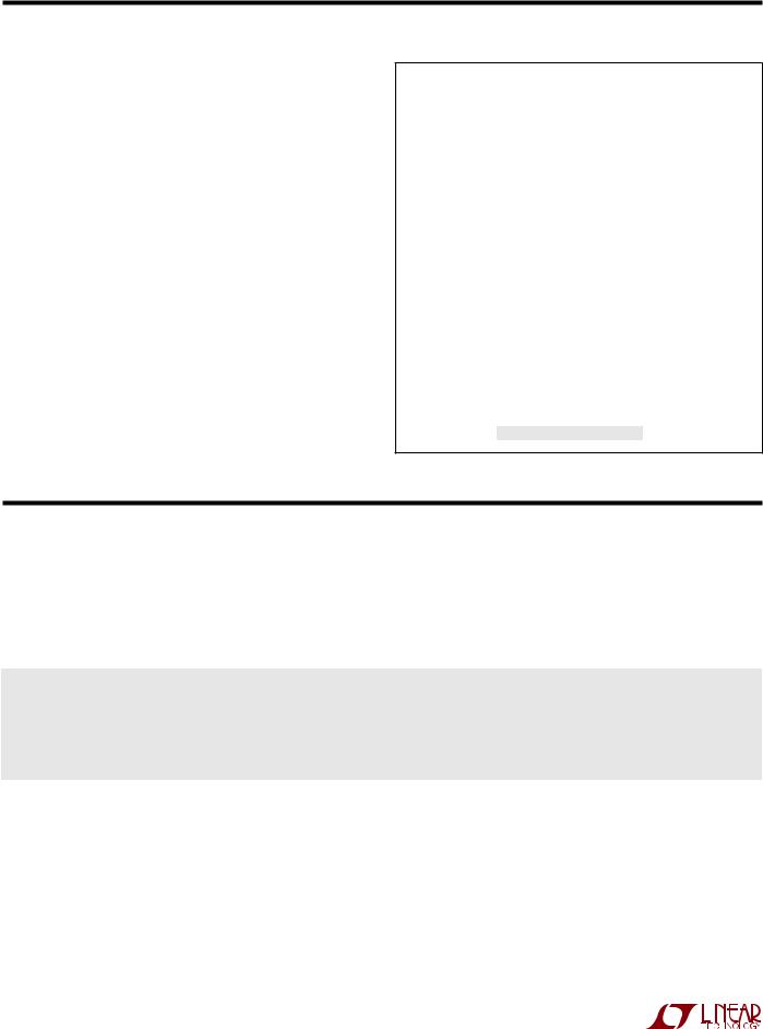
The LTC®1418 is a low power, 200ksps, 14-bit A/D converter. Data output is selectable for 14-bit parallel or serial format. This versatile device can operate from a single 5V or ±5V supply. An onboard high performance sample-and- hold, a precision reference and internal timing minimize external circuitry requirements. The low 15mW power dissipation is made even more attractive with two user selectable power shutdown modes.
The LTC1418 converts 0V to 4.096V unipolar inputs from a single 5V supply and ±2.048V bipolar inputs from ±5V supplies. DC specs include ±1.25LSB INL, ±1LSB DNL and no missing codes over temperature. Outstanding AC performance includes 82dB S/(N + D) and 94dB THD at the Nyquist input frequency of 100kHz.
The flexible output format allows either parallel or serial I/O. The SPI/MICROWIRE compatible serial I/O port can operate as either master or slave and can support clock frequencies from DC to 10MHz. A separate convert start input and a data ready signal (BUSY) allow easy control of conversion start and data transfer.
L, LT, LTC, LTM, Linear Technology and the Linear logo are registered trademarks of Linear Technology Corporation. All other trademarks are the property of their respective owners.
TYPICAL APPLICATION
Low Power, 200kHz, 14-Bit Sampling A/D Converter |
|
|||||
|
|
|
|
5V |
|
|
|
|
|
10 F |
|
|
|
|
|
|
|
VDD |
|
|
|
LTC1418 |
|
|
|
|
SER/PAR |
|
|
|
|
|
|
|
AIN+ |
|
|
|
|
|
D13 |
S/H |
|
14-BIT ADC |
14 |
|
D5 |
|
AIN– |
|
SELECTABLE |
||||
|
|
|
|
D4 (EXTCLKIN) |
||
|
|
|
|
SERIAL/ |
||
|
|
|
|
|
PARALLEL |
D3 (SCLK) |
|
|
4.096V |
|
PORT |
D2 (CLKOUT) |
|
|
|
|
|
|||
REFCOMP |
|
|
|
D1 (DOUT) |
||
BUFFER |
|
|
|
|||
10 F |
|
|
|
D0 (EXT/INT) |
||
|
|
|
|
|
|
|
|
|
8k |
|
|
|
BUSY |
VREF |
|
2.5V |
|
TIMING AND |
CS |
|
|
|
|
RD |
|||
|
|
REFERENCE |
|
LOGIC |
||
1 F |
|
|
|
CONVST |
||
|
|
|
|
|
||
|
|
|
|
|
SHDN |
|
|
|
|
|
|
|
|
|
|
|
AGND |
VSS |
DGND |
1418 TA01 |
|
|
|
|
(0V OR –5V) |
|
|
|
|
|
|
|
|
|
Typical INL Curve
|
1.0 |
|
|
|
|
|
|
|
|
|
|
|
|
|
|
(LSBs) |
0.5 |
|
|
|
|
|
|
|
|
|
|
|
|
||
0 |
|
|
|
|
|
|
|
|
|
|
|
|
|
||
INL |
|
|
|
|
|
|
|
|
–0.5 |
|
|
|
|
|
|
|
|
|
|
|
|
|
|
|
–1.0 0 |
4096 |
|
|
|
|
|
|
8192 |
12288 |
16384 |
||||
|
|
|
|
OUTPUT CODE |
|
|
|
|
|
|
|
|
|
1418 TA02 |
|
|
|
|
|
|
|
|
For more information www.linear.com/LTC1418 |
1418fa |
|
||
|
LTC1418
ABSOLUTE MAXIMUM RATINGS PACKAGE/ORDER INFORMATION
(Note 1, 2) |
|
|
|
Supply Voltage (VDD) .................................................. |
|
|
6V |
Negative Supply Voltage (VSS) |
–6V to GND |
||
Bipolar Operation Only............................. |
|
||
Total Supply Voltage (VDD to VSS) |
12V |
||
Bipolar Operation Only......................................... |
|
|
|
Analog Input Voltage (Note 3) |
|
|
|
Unipolar Operation................... |
|
–0.3V to (VDD |
+ 0.3V) |
Bipolar Operation........... |
(VSS – 0.3V) to (VDD |
+ 0.3V) |
|
Digital Input Voltage (Note 4) |
|
|
|
Unipolar Operation................................. |
|
–0.3V to 10V |
|
Bipolar Operation......................... |
|
(VSS – 0.3V) to 10V |
|
Digital Output Voltage |
|
|
|
Unipolar Operation................... |
|
–0.3V to (VDD |
+ 0.3V) |
Bipolar Operation........... |
(VSS |
– 0.3V) to (VDD |
+ 0.3V) |
Power Dissipation............................................... |
|
500mW |
|
Operation Temperature Range |
|
|
|
LTC1418C................................................. |
|
0°C to 70°C |
|
LTC1418I.............................................. |
|
–40°C to 85°C |
|
Storage Temperature Range................... |
–65°C to 150°C |
||
Lead Temperature (Soldering, 10 sec)................... |
300°C |
||
|
|
|
TOP VIEW |
|
|
||
AIN+ |
|
|
|
|
|
VDD |
|
|
|
|
|
|
|||
|
1 |
|
|
28 |
|||
AIN– |
|
|
|
|
|
VSS |
|
|
2 |
|
|
27 |
|||
|
|
|
|
|
BUSY |
||
VREF |
|
3 |
|
|
26 |
||
|
|
|
|
|
|
|
|
REFCOMP |
|
4 |
|
|
25 |
CS |
|
|
|
|
|
|
|
||
AGND |
|
5 |
|
|
24 |
CONVST |
|
|
|
|
|
|
|
|
|
D13 (MSB) |
|
6 |
|
|
23 |
RD |
|
|
|
|
|
|
|
||
D12 |
|
7 |
|
|
22 |
SHDN |
|
|
|
|
|
|
|
||
D11 |
|
8 |
|
|
21 |
SER/PAR |
|
|
|
|
|
|
|
D0 |
(EXT/INT) |
D10 |
9 |
|
|
20 |
|||
|
|
|
|
|
|
D1 |
(DOUT) |
D9 |
10 |
|
|
19 |
|||
|
|
|
|
|
|
D2 |
(CLKOUT) |
D8 |
11 |
|
|
18 |
|||
|
|
|
|
|
|
D3 |
(SCLK) |
D7 |
12 |
|
|
17 |
|||
|
|
|
|
|
|
|
|
D6 |
13 |
|
|
16 |
D4 |
(EXTCLKIN) |
|
|
|
|
|
|
|
D5 |
|
DGND |
14 |
|
|
15 |
|
||
|
|
|
|
|
|
||
G PACKAGE |
|
|
|
|
|||
OBSOLETE PACKAGE |
|||||||
28-LEAD PLASTIC SSOP |
|
N PACKAGE |
|||||
|
|
|
|
28-LEAD NARROW PDIP |
|||
TJMAX = 110°C, θJA = 95°C/W (G)
TJMAX = 110°C, θJA = 100°C/W (N)
ORDER INFORMATION
LEAD FREE FINISH |
TAPE AND REEL |
PART MARKING |
PACKAGE DESCRIPTION |
TEMPERATURE RANGE |
|
|
|
|
|
LTC1418ACG#PBF |
LTC1418ACG#TRPBF |
1418ACG |
28-Lead Plastic SSOP |
0°C to 70°C |
|
|
|
|
|
LTC1418CG#PBF |
LTC1418CG#TRPBF |
1418CG |
28-Lead Plastic SSOP |
0°C to 70°C |
|
|
|
|
|
LTC1418AIG#PBF |
LTC1418AIG#TRPBF |
1418AIG |
28-Lead Plastic SSOP |
–40°C to 85°C |
|
|
|
|
|
LTC1418IG#PBF |
LTC1418IG#TRPBF |
1418IG |
28-Lead Plastic SSOP |
–40°C to 85°C |
|
|
|
|
|
OBSOLETE PACKAGE
LTC1418ACN#PBF |
LTC1418ACN#TRPBF |
1418ACN |
28-Lead PDIP |
0°C to 70°C |
|
|
|
|
|
LTC1418CN#PBF |
LTC1418CN#TRPBF |
1418CN |
28-Lead PDIP |
0°C to 70°C |
|
|
|
|
|
LTC1418AIN#PBF |
LTC1418AIN#TRPBF |
1418AIN |
28-Lead PDIP |
–40°C to 85°C |
|
|
|
|
|
LTC1418IN#PBF |
LTC1418IN#TRPBF |
1418IN |
28-Lead PDIP |
–40°C to 85°C |
|
|
|
|
|
Consult LTC Marketing for parts specified with wider operating temperature ranges.
Consult LTC Marketing for information on nonstandard lead based finish parts.
For more information on lead free part marking, go to: http://www.linear.com/leadfree/
For more information on tape and reel specifications, go to: http://www.linear.com/tapeandreel/
|
|
|
1418fa |
|
|
||
|
|
|
|
2 |
For more information www.linear.com/LTC1418 |
|
|
|
|
||
|
|||

LTC1418
CONVERTER CHARACTERISTICS The l denotes the specifications which apply over the full operating temperature range, otherwise specifications are at TA = 25°C. (Notes 5, 6)
|
|
|
|
LTC1418 |
|
|
LTC1418A |
|
|
PARAMETER |
CONDITIONS |
|
MIN |
TYP |
MAX |
MIN |
TYP |
MAX |
UNITS |
|
|
|
|
|
|
|
|
|
|
Resolution (No Missing Codes) |
|
l |
13 |
|
|
14 |
|
|
Bits |
|
|
|
|
|
|
|
|
|
|
Integral Linearity Error |
(Note 7) |
l |
|
±0.8 |
±2 |
|
±0.5 |
±1.25 |
LSB |
|
|
|
|
|
|
|
|
|
|
Differential Linearity Error |
|
l |
|
±0.7 |
±1.5 |
|
±0.35 |
±1 |
LSB |
|
|
|
|
|
|
|
|
|
|
Offset Error |
(Note 8) |
l |
|
±5 |
±20 |
|
±2 |
±10 |
LSB |
|
|
|
|
|
|
|
|
|
|
Full-Scale Error |
Internal Reference |
|
|
±10 |
±60 |
|
±20 |
±60 |
LSB |
|
External Reference = 2.5V |
|
|
±5 |
±30 |
|
±5 |
±15 |
LSB |
|
|
|
|
|
|
|
|
|
|
Full-Scale Tempco |
IOUT(REF) = 0, Internal Reference, Commercial |
l |
|
±15 |
|
|
±10 |
±45 |
ppm/°C |
|
|
|
|
||||||
|
IOUT(REF) = 0, Internal Reference, Industrial |
|
|
|
|
|
±20 |
|
ppm/°C |
|
IOUT(REF) = 0, External Reference |
|
|
±5 |
|
|
±1 |
|
ppm/°C |
ANALOG INPUT The l denotes the specifications which apply over the full operating temperature range, otherwise specifications are at TA = 25°C. (Note 5)
SYMBOL |
PARAMETER |
CONDITIONS |
|
MIN |
TYP |
MAX |
UNITS |
|
|
|
|
|
|
|
|
VIN |
Analog Input Range (Note 9) |
4.75V ≤ VDD ≤ 5.25V (Unipolar) |
l |
|
0 to 4.096 |
|
V |
|
|
|
|||||
|
|
4.75V ≤ VDD ≤ 5.25V, –5.25V ≤ VSS ≤ –4.75V (Bipolar) |
l |
|
±2.048 |
|
V |
IIN |
Analog Input Leakage Current |
CS = High |
l |
|
|
±1 |
µA |
|
|
|
|||||
CIN |
Analog Input Capacitance |
Between Conversions (Sample Mode) |
|
|
25 |
|
pF |
|
|
During Conversions (Hold Mode) |
|
|
5 |
|
pF |
tACQ |
Sample-and-Hold Acquisition Time |
Commercial |
l |
|
300 |
1000 |
ns |
|
|
||||||
|
|
Industrial |
l |
|
300 |
1000 |
ns |
|
|
|
|
||||
|
|
|
|
|
|
|
|
DYNAMIC ACCURACY The l denotes the specifications which apply over the full operating temperature range, otherwise specifications are at TA = 25°C. (Note 5)
SYMBOL |
PARAMETER |
CONDITIONS |
|
MIN |
TYP |
MAX |
UNITS |
|
|
|
|
|
|
|
|
S/(N + D) |
Signal-to-Noise Plus Distortion Ratio |
97.5kHz Input Signal |
l |
79 |
81.5 |
|
dB |
|
|
|
|
|
|
|
|
THD |
Total Harmonic Distortion |
100kHz Input Signal, First 5 Harmonics |
l |
|
–94 |
–86 |
dB |
|
|
|
|
|
|
|
|
SFDR |
Spurious Free Dynamic Range |
100kHz Input Signal |
l |
86 |
95 |
|
dB |
|
|
|
|
|
|
|
|
IMD |
Intermodulation Distortion |
fIN1 = 97.7kHz, fIN2 = 104.2kHz |
|
|
–90 |
|
dB |
|
Full Power Bandwidth |
|
|
|
5 |
|
MHz |
|
|
|
|
|
|
|
|
|
Full Linear Bandwidth |
S/(N + D) ≥ 77dB |
|
|
0.5 |
|
MHz |
|
|
|
|
|
|
|
|
|
|
1418fa |
|
|
|
|
|
|
|
For more information www.linear.com/LTC1418 |
3 |
|
||
|

LTC1418
INTERNAL REFERENCE CHARACTERISTICS |
The l denotes the specifications which apply over the |
||||||
full operating temperature range, otherwise specifications are at TA = 25°C. (Note 5) |
|
|
|
||||
PARAMETER |
CONDITIONS |
|
|
MIN |
TYP |
MAX |
UNITS |
|
|
|
|
|
|
|
|
VREF Output Voltage |
IOUT = 0 |
|
|
2.480 |
2.500 |
2.520 |
V |
VREF Output Tempco |
IOUT = 0, Commercial |
|
l |
|
±10 |
±45 |
ppm/°C |
|
IOUT = 0, Industrial |
|
|
|
±20 |
|
ppm/°C |
VREF Line Regulation |
4.75V ≤ VDD ≤ 5.25V |
|
|
|
0.05 |
|
LSB/V |
|
–5.25V ≤ VSS ≤ –4.75V |
|
|
|
0.05 |
|
LSB/V |
VREF Output Resistance |
0.1mA ≤ | IOUT | ≤ 0.1mA |
|
|
|
8 |
|
kΩ |
DIGITAL INPUTS AND OUTPUTS The l denotes the specifications which apply over the full operating temperature range, otherwise specifications are at TA = 25°C. (Note 5)
SYMBOL |
PARAMETER |
CONDITIONS |
|
MIN |
TYP |
MAX |
UNITS |
|
|
|
|
|
|
|
|
VIH |
High Level Input Voltage |
VDD = 5.25V |
l |
2.4 |
|
|
V |
|
|
|
|||||
VIL |
Low Level Input Voltage |
VDD = 4.75V |
l |
|
|
0.8 |
V |
|
|
|
|||||
IIN |
Digital Input Current |
VIN = 0V to VDD |
l |
|
|
±10 |
µA |
|
|
|
|||||
CIN |
Digital Input Capacitance |
|
|
|
1.4 |
|
pF |
VOH |
High Level Output Voltage |
VDD = 4.75V, IO = –10μA |
|
|
4.74 |
|
V |
|
|
VDD = 4.75V, IO = –200µA |
l |
4.0 |
|
|
V |
|
|
|
|
|
|||
VOL |
Low Level Output Voltage |
VDD = 4.75V, IO = 160μA |
|
|
0.05 |
|
V |
|
|
VDD = 4.75V, IO = 1.6mA |
l |
|
0.10 |
0.4 |
V |
|
|
|
|
||||
IOZ |
Hi-Z Output Leakage D13 to D0 |
VOUT = 0V to VDD, CS High |
l |
|
|
±10 |
µA |
|
|
|
|||||
COZ |
Hi-Z Output Capacitance D13 to D0 |
CS High (Note 9) |
l |
|
|
15 |
pF |
|
|
|
|||||
ISOURCE |
Output Source Current |
VOUT = 0V |
|
|
–10 |
|
mA |
ISINK |
Output Sink Current |
VOUT = VDD |
|
|
10 |
|
mA |
POWER REQUIREMENTS The l denotes the specifications which apply over the full operating temperature range, otherwise specifications are at TA = 25°C. (Note 5)
SYMBOL |
PARAMETER |
CONDITIONS |
|
MIN |
TYP |
MAX |
UNITS |
|
|
|
|
|
|
|
|
VDD |
Positive Supply Voltage (Notes 10, 11) |
|
|
4.75 |
|
5.25 |
V |
VSS |
Negative Supply Voltage (Note 10) |
Bipolar Only (VSS = 0V for Unipolar) |
|
–4.75 |
|
–5.25 |
V |
IDD |
Positive Supply Current |
Unipolar, RD High (Note 5 ) |
l |
|
3.0 |
4.3 |
mA |
|
|
||||||
|
|
Bipolar, RD High (Note 5) |
l |
|
3.9 |
4.5 |
µA |
|
|
|
|
||||
|
Nap Mode |
SHDN = 0V, CS = 0V (Note 12) |
|
|
570 |
|
µA |
|
Sleep Mode |
SHDN = 0V, CS = 5V (Note 12) |
|
|
2 |
|
|
|
|
|
|
|
|
|
|
ISS |
Negative Supply Current |
Bipolar, RD High (Note 5) |
l |
|
1.4 |
1.8 |
mA |
|
|
||||||
|
Nap Mode |
SHDN = 0V, CS = 0V (Note 12) |
|
|
0.1 |
|
µA |
|
Sleep Mode |
SHDN = 0V, CS = 5V (Note 12) |
|
|
0.1 |
|
µA |
|
|
|
|
|
|
|
|
PDIS |
Power Dissipation |
Unipolar |
l |
|
15.0 |
21.5 |
mW |
|
|
||||||
|
|
Bipolar |
l |
|
26.5 |
31.5 |
mW |
|
|
|
|
||||
|
|
|
|
|
|
|
|
|
|
|
1418fa |
|
|
||
|
|
|
|
4 |
For more information www.linear.com/LTC1418 |
|
|
|
|
||
|
|||