

Laboratory work # 1. Diode applications
Aims: investigate properties of diodes and LEDs, get skills of the scheme mounting. Compare experimental results with theoretical foundations about diodes.
Preparation to lab work.
Learn the information about diodes and LEDs.
Show semiconductor diode i-v-characteristic.
Consider experiments’ schemes and draw them with application of Scheme Design System. Fill in the tables theoretically.
Answer the questions below in written form.
What is a semiconductor diode?
What is diode’s forward/reverse bias?
What is diode’s cathode/anode?
How can you define cathode and anode for real diode?
Explain a semiconductor diode’s behavior according to its i-v-characteristic.
What is LED?
Explain how to define the value of resistance for any resistor.
Explain how to measure voltage with multimeter.
Lab work performance.
Demonstrate presence of your home preparation for lab work to your instructor.
Pass test of 10 questions.
Get a permission to begin the work.
Mount the schemes of experiment 1A on the breadboard and perform them.
Make a conclusion about functionality of the schemes. Compare your results with theoretical ones.
Demonstrate your results to your instructor. If your results are correct you may dismount your scheme, if no – find the mistake.
Repeat steps 4 to 6 for experiment 1B.
Be ready to answer your instructor’s questions in process of work.
Complete your work, dismount your schemes, clean your working place.
Answer your instructor’s final questions, obtain your mark.
Ask your instructor’s permission to leave.
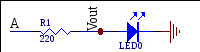
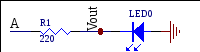
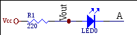
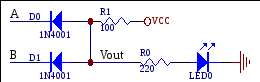
Experiment 1A.Realize the following circuit on a breadboard. Connecting A, and B inputs to either GND or VCC based on the following table, fill in the blanks. Write ON or OFF for LEDs.
|
|
INPUT |
OUTPUT |
|
|
INPUT |
OUTPUT |
|
|
INPUT |
OUTPUT | |||
|
|
A |
LED 0 ON/OFF |
Vout (V) |
|
|
A |
LED 0 ON/OFF |
Vout (V) |
|
|
A |
LED 0 ON/OFF |
Vout (V) |
|
1 |
5V |
|
|
|
1 |
5V |
|
|
|
1 |
5V |
|
|
|
2 |
0V |
|
|
|
2 |
0V |
|
|
|
2 |
0V |
|
|
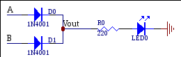
Experiment 1B.Do the similar things for the following circuits.
|
|
INPUTS |
OUTPUTS |
|
|
INPUTS |
OUTPUTS | ||||
|
|
A |
B |
LED0 |
Vout (V) |
|
|
A |
B |
LED0 |
Vout (V) |
|
1 |
0V |
0V |
|
|
|
1 |
0V |
0V |
|
|
|
2 |
0V |
5V |
|
|
|
2 |
0V |
5V |
|
|
|
3 |
5V |
0V |
|
|
|
3 |
5V |
0V |
|
|
|
4 |
5V |
5V |
|
|
|
4 |
5V |
5V |
|
|
Test questions
1. Voltages V1, V3, V4in the scheme below equal to ________ respectively.
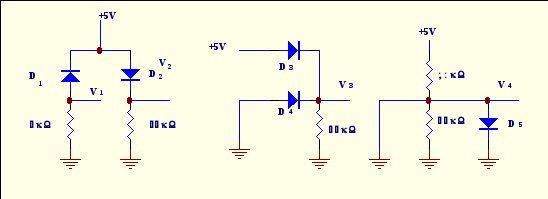
A. 4.3 V, 0, 0 B. 0, 4.3V, 0 C. 4.3 V, 4.3 V, 0 D. 0, 0, 0 E. 4.3 V, 0, 4.3 V
2. How many states has the switch got?
A. 1 B. 2 C. 3 D. 4 E. 5
3. What can you say about state of diodes 1, 2, 3 in the picture?
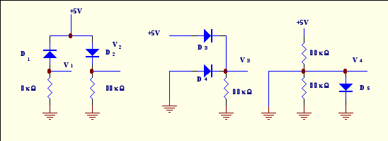
A. reverse, forward, reverse B. reverse, forward, forward
C. forward, reverse, forward D. Reverse, reverse, forward
E. forward, forward, reverse
4. The second strip to obtain resistance 560 Ω must be
A. blue B. Green C. Brown D. Yellow E. red
5. Value of resistance is 9.6 kΩ. It means that the first three strips on the resistance case (in whole the case has got 4 strips) are:
A. white, blue, red B. gray, brown, black C. Black, brown, green
D. brown, black, brown E. brown, black, red
6. Analyze the information. Fill in the gaps.
Anode voltage is +5V, cathode V is +3V. The diode is ______. Anode voltage is -5V, cathode V is -3V. The diode is ______.
A. ON, ON B. OFF,OFF C. ON, OFF D. OFF, ON E. all answers are wrong
7. Forward bias means that for diode
A. anode voltage is more positive than its cathode one
B. anode voltage is equal to or is more negative than its cathode one
C. anode voltage is positive D. anode voltage is negative E. all answers are wrong
8. For the circuit below if VA=5V VB=0V D0is _______, D1is ______, and LED0is________.
A. open, closed, ON B. open, open, ON C. closed, closed, OFF
D. closed, open, ON E. open, open, OFF

9. Calculate current through typical red LED if resistor for its limitation is equal to 330 Ω. Anode voltage of LED is 5V.
A. 10 mA B. 15 mA C. 20 mA D. 25 mA E. 30 mA
1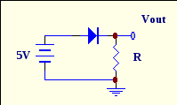 0.
For the circuit below define current through diode if R=2kΩ
0.
For the circuit below define current through diode if R=2kΩ
A. 5 mA
B. 4.5 mA
C. 4.3 mA
D. 2.15 mA
E. 0.86 mA