

- •General Information
- •Before Servicing
- •Model Identification
- •General Specifications
- •Unit Conversion Table
- •Periodic Maintenance
- •Periodic Maintenance Chart
- •Torque and Locking Agent
- •Specifications
- •Special Tools
- •Periodic Maintenance Procedures
- •Fuel System (DFI)
- •Throttle Control System Inspection
- •Engine Vacuum Synchronization Inspection
- •Idle Speed Inspection
- •Idle Speed Adjustment
- •Fuel Hose Inspection (fuel leak, damage, installation condition)
- •Cooling System
- •Coolant Level Inspection
- •Radiator Hose and Pipe Inspection (coolant leak, damage, installation condition)
- •Engine Top End
- •Valve Clearance Inspection
- •Valve Clearance Adjustment
- •Air Suction System Damage Inspection
- •Clutch
- •Clutch Operation Inspection
- •Wheels/Tires
- •Air Pressure Inspection
- •Wheel/Tire Damage Inspection
- •Tire Tread Wear Inspection
- •Wheel Bearing Damage Inspection
- •Final Drive
- •Drive Chain Lubrication Condition Inspection
- •Drive Chain Slack Inspection
- •Drive Chain Slack Adjustment
- •Wheel Alignment Inspection
- •Drive Chain Wear Inspection
- •Chain Guide Wear Inspection
- •Brakes
- •Brake Fluid Leak (Brake Hose and Pipe) Inspection
- •Brake Hose and Pipe Damage and Installation Condition Inspection
- •Brake Fluid Level Inspection
- •Brake Pad Wear Inspection
- •Brake Operation Inspection
- •Brake Light Switch Operation Inspection
- •Suspension
- •Front Forks/Rear Shock Absorber Operation Inspection
- •Front Fork Oil Leak Inspection
- •Rear Shock Absorber Oil Leak Inspection
- •Rocker Arm Operation Inspection
- •Tie-Rod Operation Inspection
- •Steering
- •Steering Play Inspection
- •Steering Play Adjustment
- •Steering Stem Bearing Lubrication
- •Steering Damper Oil Leak Inspection
- •Electrical System
- •Lights and Switches Operation Inspection
- •Headlight Aiming Inspection
- •Sidestand Switch Operation Inspection
- •Engine Stop Switch Operation Inspection
- •Others
- •Chassis Parts Lubrication
- •Bolts, Nuts and Fasteners Tightness Inspection
- •Replacement Parts
- •Air Cleaner Element Replacement
- •Fuel Hose Replacement
- •Coolant Change
- •Radiator Hose and O-ring Replacement
- •Engine Oil Change
- •Oil Filter Replacement
- •Brake Hose and Pipe Replacement
- •Brake Fluid Change
- •Master Cylinder Rubber Parts Replacement
- •Caliper Rubber Parts Replacement
- •Spark Plug Replacement
- •Fuel System (DFI)
- •Exploded View
- •DFI System
- •DFI Parts Location
- •Specifications
- •Special Tools and Sealant
- •DFI Servicing Precautions
- •DFI Servicing Precautions
- •Troubleshooting the DFI System
- •Outline
- •Inquiries to Rider
- •DFI System Troubleshooting Guide
- •Self-Diagnosis
- •Self-diagnosis Outline
- •Self-diagnosis Procedures
- •Service Code Reading
- •Service Code Erasing
- •Backups
- •Main Throttle Sensor (Service Code 11)
- •Main Throttle Sensor Removal/Adjustment
- •Main Throttle Sensor Input Voltage Inspection
- •Main Throttle Sensor Output Voltage Inspection
- •Main Throttle Sensor Resistance Inspection
- •Inlet Air Pressure Sensor #1 (Service Code 12)
- •Inlet Air Pressure Sensor #1 Removal
- •Inlet Air Pressure Sensor #1 Installation
- •Inlet Air Pressure Sensor #1 Output Voltage Inspection
- •Inlet Air Temperature Sensor (Service Code 13)
- •Inlet Air Temperature Sensor Removal/Installation
- •Inlet Air Temperature Sensor Resistance Inspection
- •Water Temperature Sensor (Service Code 14)
- •Water Temperature Sensor Removal/Installation
- •Water Temperature Sensor Resistance Inspection
- •Inlet Air Pressure Sensor #2 (Service Code 16)
- •Inlet Air Pressure Sensor #2 Removal
- •Inlet Air Pressure Sensor #2 Installation
- •Inlet Air Pressure Sensor #2 Output Voltage Inspection
- •Crankshaft Sensor (Service Code 21)
- •Crankshaft Sensor Removal/Installation
- •Crankshaft Sensor Resistance Inspection
- •Crankshaft Sensor Peak Voltage Inspection
- •Speed Sensor (Service Code 24)
- •Speed Sensor Removal/Installation
- •Speed Sensor Inspection
- •Speed Sensor Input Voltage Inspection
- •Speed Sensor Output Voltage Inspection
- •Gear Position Switch (Service Code 25)
- •Gear Position Switch Removal/Installation
- •Gear Position Switch Resistance Inspection
- •Gear Position Switch Output Voltage Inspection
- •Vehicle-down Sensor (Service Code 31)
- •Vehicle-down Sensor Removal
- •Vehicle-down Sensor Installation
- •Vehicle-down Sensor Input Voltage Inspection
- •Vehicle-down Sensor Output Voltage Inspection
- •Subthrottle Sensor (Service Code 32)
- •Subthrottle Sensor Removal/Adjustment
- •Subthrottle Sensor Input Voltage Inspection
- •Subthrottle Sensor Output Voltage Inspection
- •Subthrottle Sensor Resistance Inspection
- •Oxygen Sensor - not activated (Service Code 33 (Equipped Models))
- •Oxygen Sensor Removal/Installation
- •Oxygen Sensor Inspection
- •Exhaust Butterfly Valve Actuator Sensor (Service Code 34)
- •Exhaust Butterfly Valve Actuator Sensor Removal/Installation
- •Immobilizer Amplifier (Service Code 35 (Equipped Models))
- •Antenna Resistance Inspection
- •Amplifier Input Voltage Inspection
- •Blank Key Detection (Service Code 36 (Equipped Models))
- •User Key Inspection
- •ECU Communication Error (Service Code 39)
- •ECU Communication Line Inspection
- •Stick Coils #1, #2, #3, #4 (Service Code 51, 52, 53, 54)
- •Stick Coil Removal/Installation
- •Stick Coil Primary Winding Resistance Inspection
- •Stick Coil Input Voltage Inspection
- •Radiator Fan Relay (Service Code 56)
- •Radiator Fan Relay Removal/Installation
- •Radiator Fan Relay Inspection
- •Subthrottle Valve Actuator (Service Code 62)
- •Subthrottle Valve Actuator Removal
- •Subthrottle Valve Actuator Inspection
- •Subthrottle Valve Actuator Resistance Inspection
- •Exhaust Butterfly Valve Actuator (Service Code 63)
- •Exhaust Butterfly Valve Actuator Removal
- •Exhaust Butterfly Valve Actuator Installation
- •Exhaust Butterfly Valve Actuator Inspection
- •Air Switching Valve (Service Code 64)
- •Air Switching Valve Removal/Installation
- •Air Switching Valve Inspection
- •Oxygen Sensor Heater (Service Code 67 (Equipped Models))
- •Oxygen Sensor Heater Removal/Installation
- •Oxygen Sensor Heater Resistance Inspection
- •Oxygen Sensor - Incorrect Output Voltage (Service Code 94 (Equipped Models))
- •Oxygen Sensor Removal/Installation
- •Oxygen Sensor Inspection
- •Warning Indicator Light (LED)
- •Light (LED) Inspection
- •ECU Identification
- •ECU Removal
- •ECU Installation
- •ECU Power Supply Inspection
- •DFI Power Source
- •ECU Fuse Removal
- •ECU Fuse Installation
- •ECU Fuse Inspection
- •ECU Main Relay Removal/Installation
- •ECU Main Relay Inspection
- •Fuel Line
- •Fuel Pressure Inspection
- •Fuel Flow Rate Inspection
- •Fuel Pump
- •Fuel Pump Removal
- •Fuel Pump Installation
- •Fuel Pump Operation Inspection
- •Fuel Pump Operating Voltage Inspection
- •Pressure Regulator Removal
- •Fuel Filter Cleaning
- •Fuel Injectors
- •Primary Fuel Injector Removal/Installation
- •Secondary Fuel Injector Removal/Installation
- •Fuel Injector Audible Inspection
- •Fuel Injector Resistance Inspection
- •Fuel Injector Power Source Voltage Inspection
- •Fuel Injector Output Voltage Inspection
- •Fuel Injector Fuel Line Inspection
- •Throttle Grip and Cables
- •Free Play Inspection
- •Free Play Adjustment
- •Cable Installation
- •Cable Lubrication
- •Throttle Body Assy
- •Idle Speed Inspection/Adjustment
- •Synchronization Inspection/Adjustment
- •Throttle Body Assy Removal
- •Throttle Body Assy Installation
- •Throttle Body Assy Disassembly
- •Throttle Body Assy Assembly
- •Nozzle Assy
- •Nozzle Assy Removal
- •Nozzle Assy Installation
- •Nozzle Assy Disassembly
- •Nozzle Assy Assembly
- •Air Cleaner
- •Air Cleaner Element Removal/Installation
- •Air Cleaner Element Inspection
- •Air Cleaner Oil Draining
- •Air Cleaner Housing Removal
- •Air Cleaner Housing Installation
- •Air Cleaner Housing Disassembly
- •Air Cleaner Housing Assembly
- •Air Line
- •Air Inlet Duct Removal
- •Air Inlet Duct Installation
- •Fuel Tank
- •Fuel Tank Removal
- •Fuel Tank Installation
- •Fuel Tank Inspection
- •Fuel Tank Cleaning
- •Evaporative Emission Control System (CAL, SEA and TH Models)
- •Parts Removal/Installation
- •Hose Inspection
- •Separator Inspection
- •Separator Operation Test
- •Canister Inspection
- •Cooling System
- •Exploded View
- •Coolant Flow Chart
- •Specifications
- •Special Tools
- •Coolant
- •Coolant Deterioration Inspection
- •Coolant Level Inspection
- •Coolant Draining
- •Coolant Filling
- •Pressure Testing
- •Cooling System Flushing
- •Coolant Reserve Tank Removal
- •Coolant Reserve Tank Installation
- •Water Pump
- •Water Pump Removal
- •Water Pump Installation
- •Water Pump Inspection
- •Water Pump Impeller Disassembly/Assembly
- •Water Pump Impeller Inspection
- •Water Pump Housing Disassembly
- •Water Pump Housing Assembly
- •Mechanical Seal Inspection
- •Radiator
- •Radiator and Radiator Fan Removal
- •Radiator and Radiator Fan Installation
- •Radiator Inspection
- •Radiator Cap Inspection
- •Radiator Filler Neck Inspection
- •Thermostat
- •Thermostat Removal
- •Thermostat Installation
- •Thermostat Inspection
- •Hoses and Pipes
- •Hose Installation
- •Hose Inspection
- •Water Temperature Sensor
- •Water Temperature Sensor Removal/Installation
- •Water Temperature Sensor Inspection
- •Engine Top End
- •Exploded View
- •Exhaust System Identification
- •Specifications
- •Special Tools and Sealant
- •Clean Air System
- •Air Suction Valve Removal
- •Air Suction Valve Installation
- •Air Suction Valve Inspection
- •Air Switching Valve Removal
- •Air Switching Valve Installation
- •Air Switching Valve Operation Test
- •Air Switching Valve Unit Test
- •Clean Air System Hose Inspection
- •Cylinder Head Cover
- •Cylinder Head Cover Removal
- •Cylinder Head Cover Installation
- •Camshaft Chain Tensioner
- •Camshaft Chain Tensioner Removal
- •Camshaft Chain Tensioner Installation
- •Camshaft, Camshaft Chain
- •Camshaft Removal
- •Camshaft Installation
- •Camshaft, Camshaft Cap Wear Inspection
- •Camshaft Runout Inspection
- •Cam Wear Inspection
- •Camshaft Chain Removal
- •Cylinder Head
- •Cylinder Compression Measurement
- •Cylinder Head Removal
- •Cylinder Head Installation
- •Cylinder Head Warp Inspection
- •Valves
- •Valve Clearance Inspection
- •Valve Removal
- •Valve Installation
- •Valve Guide Removal
- •Valve Guide Installation
- •Valve-to-Guide Clearance Measurement (Wobble Method)
- •Valve Seat Inspection
- •Valve Seat Repair
- •Throttle Body Assy Holder
- •Throttle Body Assy Holder Removal
- •Throttle Body Assy Holder Installation
- •Muffler
- •Muffler Body Removal
- •Muffler Body Installation
- •Premuffler Chamber Removal
- •Premuffler Chamber Installation
- •Exhaust Pipe Removal
- •Exhaust Pipe Installation
- •Exhaust Butterfly Valve Cable Removal
- •Exhaust Butterfly Valve Cable Installation
- •Clutch
- •Exploded View
- •Specifications
- •Special Tool and Sealant
- •Clutch Lever and Cable
- •Clutch Lever Free Play Inspection
- •Clutch Lever Free Play Adjustment
- •Cable Removal
- •Cable Installation
- •Cable Lubrication
- •Clutch Lever Installation
- •Clutch Cover
- •Clutch Cover Removal
- •Clutch Cover Installation
- •Release Shaft Removal
- •Release Shaft Installation
- •Clutch Cover Disassembly
- •Clutch Cover Assembly
- •Clutch
- •Clutch Removal
- •Clutch Installation
- •Spring Plate Free Play Measurement
- •Spring Plate Free Play Adjustment
- •Clutch Plate, Wear, Damage Inspection
- •Clutch Plate Warp Inspection
- •Clutch Spring Free Length Measurement
- •Clutch Housing Finger Inspection
- •Clutch Housing Spline Inspection
- •Damper Cam Inspection
- •Engine Lubrication System
- •Exploded View
- •Engine Oil Flow Chart
- •Specifications
- •Special Tools and Sealant
- •Engine Oil and Oil Filter
- •Oil Level Inspection
- •Engine Oil Change
- •Oil Filter Replacement
- •Oil Pan Removal
- •Oil Pan Installation
- •Oil Pressure Relief Valve
- •Oil Pressure Relief Valve Removal
- •Oil Pressure Relief Valve Installation
- •Oil Pressure Relief Valve Inspection
- •Oil Pump
- •Oil Pump Removal
- •Oil Pump Installation
- •Oil Pump Drive Gear Removal
- •Oil Pump Drive Gear Installation
- •Oil Pump Drive Gear Shaft Removal
- •Oil Pump Drive Gear Shaft Installation
- •Oil Cooler
- •Oil Cooler Removal
- •Oil Cooler Installation
- •Oil Cooler/Oil Filter Case Removal
- •Oil Cooler/Oil Filter Case Installation
- •Oil Pressure Measurement
- •Oil Pressure Measurement
- •Oil Pressure Switch
- •Oil Pressure Switch Removal
- •Oil Pressure Switch Installation
- •Engine Removal/Installation
- •Exploded View
- •Special Tool
- •Engine Removal/Installation
- •Engine Removal
- •Engine Installation
- •Crankshaft/Transmission
- •Exploded View
- •Specifications
- •Special Tools and Sealants
- •Crankcase
- •Crankcase Splitting
- •Crankcase Assembly
- •Crankshaft and Connecting Rods
- •Crankshaft Removal
- •Crankshaft Installation
- •Connecting Rod Removal
- •Connecting Rod Installation
- •Crankshaft/Connecting Rod Cleaning
- •Connecting Rod Bend Inspection
- •Connecting Rod Twist Inspection
- •Connecting Rod Big End Side Clearance Inspection
- •Connecting Rod Big End Bearing Insert/Crankpin Wear Inspection
- •Crankshaft Side Clearance Inspection
- •Crankshaft Runout Inspection
- •Pistons
- •Piston Removal
- •Piston Installation
- •Cylinder (Upper Crankcase) Wear Inspection
- •Piston Wear Inspection
- •Piston Ring, Piston Ring Groove Wear Inspection
- •Piston Ring Groove Width Inspection
- •Piston Ring Thickness Inspection
- •Piston Ring End Gap Inspection
- •Starter Idle Gear and Starter Clutch
- •Starter Idle Gear Removal
- •Starter Idle Gear Installation
- •Starter Clutch Removal
- •Starter Clutch Installation
- •Starter Clutch Disassembly
- •Starter Clutch Assembly
- •Starter Clutch Inspection
- •Transmission
- •Transmission Assy Removal
- •Transmission Assy Disassembly
- •Transmission Assy Assembly
- •Transmission Assy Installation
- •Transmission Shaft Removal
- •Transmission Shaft Installation
- •Transmission Shaft Disassembly
- •Transmission Shaft Assembly
- •Shift Drum and Fork Removal
- •Shift Drum and Fork Installation
- •Shift Drum Disassembly
- •Shift Drum Assembly
- •Shift Fork Bending Inspection
- •Shift Fork/Gear Groove Wear Inspection
- •Shift Fork Guide Pin/Drum Groove Wear Inspection
- •Gear Dog and Gear Dog Hole Damage Inspection
- •External Shift Mechanism
- •Shift Pedal Removal
- •Shift Pedal Installation
- •External Shift Mechanism Removal
- •External Shift Mechanism Installation
- •External Shift Mechanism Inspection
- •Wheels/Tires
- •Exploded View
- •Specifications
- •Special Tools
- •Wheels (Rims)
- •Front Wheel Removal
- •Front Wheel Installation
- •Rear Wheel Removal
- •Rear Wheel Installation
- •Wheel Inspection
- •Axle Inspection
- •Balance Inspection
- •Balance Adjustment
- •Balance Weight Removal
- •Balance Weight Installation
- •Tires
- •Air Pressure Inspection/Adjustment
- •Tire Inspection
- •Tire Removal
- •Tire Installation
- •Tire Repair
- •Hub Bearing
- •Hub Bearing Removal
- •Hub Bearing Installation
- •Hub Bearing Inspection
- •Hub Bearing Lubrication
- •Final Drive
- •Exploded View
- •Specifications
- •Special Tools
- •Drive Chain
- •Drive Chain Slack Inspection
- •Drive Chain Slack Adjustment
- •Wheel Alignment Inspection/Adjustment
- •Drive Chain Wear Inspection
- •Drive Chain Lubrication
- •Drive Chain Guide Wear Inspection
- •Drive Chain Removal
- •Sprocket, Coupling
- •Engine Sprocket Removal
- •Engine Sprocket Installation
- •Rear Sprocket Removal
- •Rear Sprocket Installation
- •Coupling Installation
- •Coupling Bearing Removal
- •Coupling Bearing Installation
- •Coupling Bearing Inspection
- •Coupling Bearing Lubrication
- •Coupling Damper Inspection
- •Sprocket Wear Inspection
- •Rear Sprocket Warp Inspection
- •Brakes
- •Exploded View
- •Specifications
- •Special Tools
- •Brake Lever, Brake Pedal
- •Brake Lever Position Adjustment
- •Brake Pedal Position Inspection
- •Brake Pedal Position Adjustment
- •Brake Pedal Removal
- •Brake Pedal Installation
- •Calipers
- •Front Caliper Removal
- •Rear Caliper Removal
- •Caliper Installation
- •Front Caliper Disassembly
- •Front Caliper Assembly
- •Rear Caliper Disassembly
- •Rear Caliper Assembly
- •Caliper Fluid Seal Damage Inspection
- •Caliper Dust Seal Damage Inspection
- •Caliper Piston and Cylinder Damage Inspection
- •Rear Caliper Holder Shaft Wear Inspection
- •Brake Pads
- •Front Brake Pad Removal
- •Front Brake Pad Installation
- •Rear Brake Pad Removal
- •Rear Brake Pad Installation
- •Brake Pad Wear Inspection
- •Master Cylinder
- •Front Master Cylinder Removal
- •Front Master Cylinder Installation
- •Rear Master Cylinder Removal
- •Rear Master Cylinder Installation
- •Front Master Cylinder Disassembly
- •Rear Master Cylinder Disassembly
- •Master Cylinder Assembly
- •Master Cylinder Inspection (Visual Inspection)
- •Brake Disc
- •Brake Disc Removal
- •Brake Disc Installation
- •Brake Disc Wear Inspection
- •Brake Disc Warp Inspection
- •Brake Fluid
- •Brake Fluid Level Inspection
- •Brake Fluid Change
- •Brake Line Bleeding
- •Brake Hose
- •Brake Hose Removal/Installation
- •Brake Hose Inspection
- •Suspension
- •Exploded View
- •Specifications
- •Special Tools
- •Front Fork
- •Rebound Damping Force Adjustment
- •Compression Damping Force Adjustment
- •Spring Preload Adjustment
- •Front Fork Removal (Each Fork Leg)
- •Front Fork Installation (Each Fork Leg)
- •Front Fork Oil Change
- •Front Fork Disassembly
- •Front Fork Assembly
- •Inner Tube Inspection
- •Dust Seal Inspection
- •Spring Tension Inspection
- •Rear Shock Absorber
- •Rebound Damping Force Adjustment
- •Compression Damping Force Adjustment
- •Spring Preload Adjustment
- •Rear Shock Absorber Removal
- •Rear Shock Absorber Installation
- •Rear Shock Absorber Inspection
- •Rear Shock Absorber Scrapping
- •Swingarm
- •Swingarm Removal
- •Swingarm Installation
- •Swingarm Bearing Removal
- •Swingarm Bearing Installation
- •Swingarm Bearing, Sleeve Inspection
- •Swingarm Bearing Lubrication
- •Tie-Rod, Rocker Arm
- •Tie-Rod Removal
- •Tie-Rod Installation
- •Rocker Arm Removal
- •Rocker Arm Installation
- •Tie-Rod and Rocker Arm Bearing Removal
- •Tie-Rod and Rocker Arm Bearing Installation
- •Tie-Rod/Rocker Arm Bearing, Sleeve Inspection
- •Tie-Rod/Rocker Arm Bearing Lubrication
- •Steering
- •Exploded View
- •Specifications
- •Special Tools
- •Steering
- •Steering Inspection
- •Steering Adjustment
- •Steering Damper
- •Damping Force Adjustment
- •Steering Damper Removal
- •Steering Damper Installation
- •Steering Damper Oil Leak Inspection
- •Steering Stem
- •Stem, Stem Bearing Removal
- •Stem, Stem Bearing Installation
- •Steering Stem Bearing Lubrication
- •Steering Stem Warp Inspection
- •Stem Cap Deterioration, Damage Inspection
- •Handlebar
- •Handlebar Removal
- •Handlebar Installation
- •Frame
- •Exploded View
- •Seats
- •Front Seat Removal
- •Front Seat Installation
- •Rear Seat Removal
- •Rear Seat Installation
- •Fairings
- •Lower Fairing Removal
- •Lower Fairing Installation
- •Lower Inner Fairing Removal
- •Lower Inner Fairing Installation
- •Upper Fairing Assembly Removal
- •Upper Fairing Assembly Installation
- •Center Fairing Removal
- •Center Fairing Installation
- •Upper Fairing Removal
- •Upper Fairing Installation
- •Upper Center Fairing Removal
- •Upper Center Fairing Installation
- •Upper Inner Fairing Removal
- •Upper Inner Fairing Installation
- •Center Inner Fairing Removal
- •Center Inner Fairing Installation
- •Inner Fairing Removal
- •Inner Fairing Installation
- •Fairing Cover Removal
- •Fairing Cover Installation
- •Side Covers
- •Side Cover Removal
- •Side Cover Installation
- •Seat Covers
- •Seat Cover Removal
- •Seat Cover Installation
- •Upper Seat Cover Installation (Only on Ninja ZX-6R MONSTER ENERGY® Model)
- •Fenders
- •Front Fender Removal
- •Front Fender Installation
- •Flap and Rear Fender Removal
- •Flap and Rear Fender Installation
- •Frame
- •Rear Frame Rear Removal
- •Rear Frame Rear Installation
- •Rear Frame Front Removal
- •Rear Frame Front Installation
- •Frame Inspection
- •Windshield
- •Windshield Removal
- •Windshield Installation
- •Guard
- •Mud Guard Removal
- •Mud Guard Installation
- •Sidestand
- •Sidestand Removal
- •Sidestand Installation
- •Electrical System
- •Exploded View
- •Specifications
- •Special Tools and Sealant
- •Parts Location
- •Wiring Diagram (US, CAL and CA Models)
- •Wiring Diagram (Other than US, CAL and CA Models)
- •Precautions
- •Electrical Wiring
- •Wiring Inspection
- •Battery
- •Battery Removal
- •Battery Installation
- •Battery Activation
- •Precautions
- •Interchange
- •Charging Condition Inspection
- •Refreshing Charge
- •Charging System
- •Alternator Cover Removal
- •Alternator Cover Installation
- •Stator Coil Removal
- •Stator Coil Installation
- •Alternator Rotor Removal
- •Alternator Rotor Installation
- •Charging Voltage Inspection
- •Alternator Inspection
- •Regulator/Rectifier Inspection
- •Ignition System
- •Crankshaft Sensor Removal
- •Crankshaft Sensor Installation
- •Crankshaft Sensor Inspection
- •Crankshaft Sensor Peak Voltage Inspection
- •Stick Coil Removal
- •Stick Coil Installation
- •Stick Coil Inspection
- •Stick Coil Primary Peak Voltage Inspection
- •Spark Plug Removal
- •Spark Plug Installation
- •Spark Plug Condition Inspection
- •Interlock Operation Inspection
- •IC Igniter Inspection
- •Electric Starter System
- •Starter Motor Removal
- •Starter Motor Installation
- •Starter Motor Disassembly
- •Starter Motor Assembly
- •Brush Inspection
- •Commutator Cleaning and Inspection
- •Armature Inspection
- •Brush Lead Inspection
- •Right-hand End Cover Assembly Inspection
- •Starter Relay Inspection
- •Lighting System
- •Headlight Beam Horizontal Adjustment
- •Headlight Beam Vertical Adjustment
- •Headlight Bulb Replacement
- •City Light Bulb Replacement
- •Headlight Removal/Installation
- •Tail/Brake Light (LED) Removal/Installation
- •License Plate Light Bulb Replacement
- •Turn Signal Light Bulb Replacement
- •Turn Signal Relay Inspection
- •Air Switching Valve
- •Air Switching Valve Operation Test
- •Air Switching Valve Unit Test
- •Radiator Fan System
- •Fan Motor Inspection
- •Meter, Gauge, Indicator Unit
- •Meter Unit Removal/Installation
- •Meter Unit Disassembly
- •Electronic Unit (Combination Meter) Inspection
- •Immobilizer System (Equipped Models)
- •Operational Cautions
- •Key Registration
- •Immobilizer System Parts Replacement
- •Immobilizer System Inspection
- •Switches and Sensors
- •Brake Light Timing Inspection
- •Brake Light Timing Adjustment
- •Switch Inspection
- •Water Temperature Sensor Inspection
- •Speed Sensor Removal
- •Speed Sensor Installation
- •Speed Sensor Inspection
- •Fuel Reserve Switch Inspection
- •Oxygen Sensor Removal (Equipped Models)
- •Oxygen Sensor Installation (Equipped Models)
- •Oxygen Sensor Inspection (Equipped Models)
- •Oxygen Sensor Heater Inspection (Equipped Models)
- •Gear Position Switch Removal
- •Gear Position Switch Installation
- •Gear Position Switch Inspection
- •Relay Box
- •Relay Box Removal
- •Relay Circuit Inspection
- •Diode Circuit Inspection
- •Fuse
- •30 A Main Fuse Removal
- •Fuse Box Fuse Removal
- •10 A ECU Fuse Removal
- •Fuse Installation
- •Fuse Inspection
- •Appendix
- •Cable, Wire, and Hose Routing
- •Troubleshooting Guide
FUEL SYSTEM (DFI) 3-25
Troubleshooting the DFI System
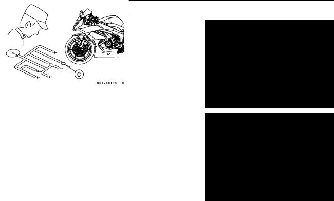
The warning indicator light (LED) [A] is used for the FI indicator, immobilizer indicator (immobilizer models) and oil pressure warning indicator.
Outline
When a problem occurs with DFI system, the warning indicator light (LED) [A] and FI warning symbol [B] blinks to alert the rider. In addition, the condition of the problem is stored in the memory of the ECU. For models equipped with an immobilizer system, the warning indicator light (LED) and immobilizer warning symbol [C] blinks, when a problem occurs in the system.
With the engine stopped and turned in the self-diagnosis mode, the service code [A] is displayed on the LCD (Liquid Crystal Display) by the number of two digits.
If the problem is with the following parts, the ECU can not recognize these problem. Therefore, the warning indicator light (LED), FI and/or immobilizer warning symbols do not blinks, and service code is not displayed.
LCD for Meter Unit Fuel Pump
Fuel Pump Relay
Primary and Secondary Fuel Injectors
Stick Coil Secondary Wiring and Ground Wiring ECU Main Relay
ECU Power Source Wiring and Ground Wiring
3-26 FUEL SYSTEM (DFI)
Troubleshooting the DFI System
When the service code [A] is displayed, for first ask the rider about the conditions [B] of trouble, and then start to determine the cause [C] of problem.
As a pre-diagnosis inspection, check the ECU for ground and power supply, the fuel line for no fuel leaks, and for correct pressure. The pre-diagnosis items are not indicated by the warning indicator light (LED) and FI warning symbol.
Don’t rely solely on the DFI self-diagnosis function, use common sense.
Even when the DFI system is operating normally, the warning indicator light (LED) and FI warning symbol may blink under strong electrical interference. Additional measures are not required. Turn the ignition switch OFF to stop the indicator light and symbol.
If the warning indicator light (LED) and FI warning symbol of the motorcycle brought in for repair still blinks, check the service code.
When the repair has been done, the FI warning symbol goes off. But the service codes stored in memory of the ECU are not erased to preserve the problem history. The problem history can be referred using the KDS (Kawasaki Diagnostic System) when solving unstable problems.
When the motorcycle is down, the vehicle-down sensor operates and the ECU shuts off the fuel pump relay, fuel injectors (primary and secondary) and ignition system. The ignition switch is left ON. If the starter button is pushed, the electric starter turns but the engine does not start. When the starter button is pushed, the warning indicator light (LED) and FI warning symbol blink but the service code is not displayed. To start the engine again, raise the motorcycle, turn the ignition switch OFF, and then ON.
Much of the DFI system troubleshooting work consists of confirming continuity of the wiring. The DFI parts are assembled and adjusted with precision, and it is impossible to disassemble or repair them.
FUEL SYSTEM (DFI) 3-27
Troubleshooting the DFI System
•When checking the DFI parts, use a digital meter which can be read two decimal place voltage or resistance.
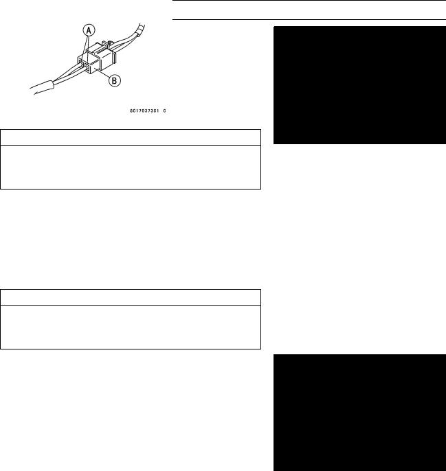
○The DFI part connectors [A] have seals [B], including the ECU. When measuring the input or output voltage with the connector joined, use the needle adapter set [C]. Insert the needle adapter inside the seal until the needle adapter reaches the terminal.
Special Tool - Needle Adapter Set: 57001-1457
CAUTION
Insert the needle adapter straight along the terminal in the connector to prevent short-circuit between terminals.
•Make sure that measuring points are correct in the connector, noting the position of the lock [D] and the lead color before measurement. Do not reverse connections of a digital meter.
•Be careful not to short-circuit the leads of the DFI or electrical system parts by contact between adapters.
•Turn the ignition switch ON and measure the voltage with the connector joined.
CAUTION
Incorrect, reverse connection or short circuit by needle adapters could damage the DFI or electrical system parts.
○After measurement, remove the needle adapters and apply silicone sealant to the seals [A] of the connector [B] for waterproofing.
Sealant - Kawasaki Bond (Silicone Sealant): 56019-120
•Always check battery condition before replacing the DFI parts. A fully charged battery is a must for conducting accurate tests of the DFI system.
•Trouble may involve one or in some cases all items. Never replace a defective part without determining what CAUSED the problem. If the problem was caused by some other item or items, they too must be repaired or replaced, or the new replacement part will soon fail again.
•Measure coil winding resistance when the DFI part is cold (at room temperature).
•Make sure all connectors in the circuit are clean and tight, and examine wires for signs of burning, fraying, short, etc. Deteriorated wires and bad connections can cause reappearance of problems and unstable operation of the DFI system.
 If any wiring is deteriorated, replace the wiring.
3-28 FUEL SYSTEM (DFI)
Troubleshooting the DFI System
•Pull each connector [A] apart and inspect it for corrosion, dirt, and damage.
 If the connector is corroded or dirty, clean it carefully. If it is damaged, replace it. Connect the connectors securely.
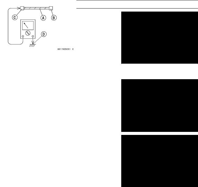
•Check the wiring for continuity.
○Use the wiring diagram to find the ends of the lead which is suspected of being a problem.
○Connect the hand tester between the ends of the leads.
Special Tool - Hand Tester: 57001-1394
○Set the tester to the × 1 Ω range, and read the tester.
 If the tester does not read 0 Ω, the lead is defective. Replace the lead or the main harness.
○If both ends of a harness [A] are far apart, ground [B] the one end [C], using a jumper lead [D] and check the continuity between the end [E] and the ground [F]. This enables to check a long harness for continuity. If the harness is open, repair or replace the harness.
○When checking a harness [A] for short circuit, open one end [B] and check the continuity between the other end [C] and ground [D]. If there is continuity, the harness has a short circuit to ground, and it must be repaired or replaced.
•Narrow down suspicious locations by repeating the continuity tests from the ECU connectors.
 If no abnormality is found in the wiring or connectors, the DFI parts are the next likely suspects. Check the part, starting with input and output voltages. However, there is no way to check the ECU itself.
 If an abnormality is found, replace the affected DFI part.
 If no abnormality is found in the wiring, connectors, and DFI parts, replace the ECU.