

- •General Information
- •Before Servicing
- •Model Identification
- •General Specifications
- •Unit Conversion Table
- •Periodic Maintenance
- •Periodic Maintenance Chart
- •Torque and Locking Agent
- •Specifications
- •Special Tools
- •Periodic Maintenance Procedures
- •Fuel System (DFI)
- •Throttle Control System Inspection
- •Engine Vacuum Synchronization Inspection
- •Idle Speed Inspection
- •Idle Speed Adjustment
- •Fuel Hose Inspection (fuel leak, damage, installation condition)
- •Cooling System
- •Coolant Level Inspection
- •Radiator Hose and Pipe Inspection (coolant leak, damage, installation condition)
- •Engine Top End
- •Valve Clearance Inspection
- •Valve Clearance Adjustment
- •Air Suction System Damage Inspection
- •Clutch
- •Clutch Operation Inspection
- •Wheels/Tires
- •Air Pressure Inspection
- •Wheel/Tire Damage Inspection
- •Tire Tread Wear Inspection
- •Wheel Bearing Damage Inspection
- •Final Drive
- •Drive Chain Lubrication Condition Inspection
- •Drive Chain Slack Inspection
- •Drive Chain Slack Adjustment
- •Wheel Alignment Inspection
- •Drive Chain Wear Inspection
- •Chain Guide Wear Inspection
- •Brakes
- •Brake Fluid Leak (Brake Hose and Pipe) Inspection
- •Brake Hose and Pipe Damage and Installation Condition Inspection
- •Brake Fluid Level Inspection
- •Brake Pad Wear Inspection
- •Brake Operation Inspection
- •Brake Light Switch Operation Inspection
- •Suspension
- •Front Forks/Rear Shock Absorber Operation Inspection
- •Front Fork Oil Leak Inspection
- •Rear Shock Absorber Oil Leak Inspection
- •Rocker Arm Operation Inspection
- •Tie-Rod Operation Inspection
- •Steering
- •Steering Play Inspection
- •Steering Play Adjustment
- •Steering Stem Bearing Lubrication
- •Steering Damper Oil Leak Inspection
- •Electrical System
- •Lights and Switches Operation Inspection
- •Headlight Aiming Inspection
- •Sidestand Switch Operation Inspection
- •Engine Stop Switch Operation Inspection
- •Others
- •Chassis Parts Lubrication
- •Bolts, Nuts and Fasteners Tightness Inspection
- •Replacement Parts
- •Air Cleaner Element Replacement
- •Fuel Hose Replacement
- •Coolant Change
- •Radiator Hose and O-ring Replacement
- •Engine Oil Change
- •Oil Filter Replacement
- •Brake Hose and Pipe Replacement
- •Brake Fluid Change
- •Master Cylinder Rubber Parts Replacement
- •Caliper Rubber Parts Replacement
- •Spark Plug Replacement
- •Fuel System (DFI)
- •Exploded View
- •DFI System
- •DFI Parts Location
- •Specifications
- •Special Tools and Sealant
- •DFI Servicing Precautions
- •DFI Servicing Precautions
- •Troubleshooting the DFI System
- •Outline
- •Inquiries to Rider
- •DFI System Troubleshooting Guide
- •Self-Diagnosis
- •Self-diagnosis Outline
- •Self-diagnosis Procedures
- •Service Code Reading
- •Service Code Erasing
- •Backups
- •Main Throttle Sensor (Service Code 11)
- •Main Throttle Sensor Removal/Adjustment
- •Main Throttle Sensor Input Voltage Inspection
- •Main Throttle Sensor Output Voltage Inspection
- •Main Throttle Sensor Resistance Inspection
- •Inlet Air Pressure Sensor #1 (Service Code 12)
- •Inlet Air Pressure Sensor #1 Removal
- •Inlet Air Pressure Sensor #1 Installation
- •Inlet Air Pressure Sensor #1 Output Voltage Inspection
- •Inlet Air Temperature Sensor (Service Code 13)
- •Inlet Air Temperature Sensor Removal/Installation
- •Inlet Air Temperature Sensor Resistance Inspection
- •Water Temperature Sensor (Service Code 14)
- •Water Temperature Sensor Removal/Installation
- •Water Temperature Sensor Resistance Inspection
- •Inlet Air Pressure Sensor #2 (Service Code 16)
- •Inlet Air Pressure Sensor #2 Removal
- •Inlet Air Pressure Sensor #2 Installation
- •Inlet Air Pressure Sensor #2 Output Voltage Inspection
- •Crankshaft Sensor (Service Code 21)
- •Crankshaft Sensor Removal/Installation
- •Crankshaft Sensor Resistance Inspection
- •Crankshaft Sensor Peak Voltage Inspection
- •Speed Sensor (Service Code 24)
- •Speed Sensor Removal/Installation
- •Speed Sensor Inspection
- •Speed Sensor Input Voltage Inspection
- •Speed Sensor Output Voltage Inspection
- •Gear Position Switch (Service Code 25)
- •Gear Position Switch Removal/Installation
- •Gear Position Switch Resistance Inspection
- •Gear Position Switch Output Voltage Inspection
- •Vehicle-down Sensor (Service Code 31)
- •Vehicle-down Sensor Removal
- •Vehicle-down Sensor Installation
- •Vehicle-down Sensor Input Voltage Inspection
- •Vehicle-down Sensor Output Voltage Inspection
- •Subthrottle Sensor (Service Code 32)
- •Subthrottle Sensor Removal/Adjustment
- •Subthrottle Sensor Input Voltage Inspection
- •Subthrottle Sensor Output Voltage Inspection
- •Subthrottle Sensor Resistance Inspection
- •Oxygen Sensor - not activated (Service Code 33 (Equipped Models))
- •Oxygen Sensor Removal/Installation
- •Oxygen Sensor Inspection
- •Exhaust Butterfly Valve Actuator Sensor (Service Code 34)
- •Exhaust Butterfly Valve Actuator Sensor Removal/Installation
- •Immobilizer Amplifier (Service Code 35 (Equipped Models))
- •Antenna Resistance Inspection
- •Amplifier Input Voltage Inspection
- •Blank Key Detection (Service Code 36 (Equipped Models))
- •User Key Inspection
- •ECU Communication Error (Service Code 39)
- •ECU Communication Line Inspection
- •Stick Coils #1, #2, #3, #4 (Service Code 51, 52, 53, 54)
- •Stick Coil Removal/Installation
- •Stick Coil Primary Winding Resistance Inspection
- •Stick Coil Input Voltage Inspection
- •Radiator Fan Relay (Service Code 56)
- •Radiator Fan Relay Removal/Installation
- •Radiator Fan Relay Inspection
- •Subthrottle Valve Actuator (Service Code 62)
- •Subthrottle Valve Actuator Removal
- •Subthrottle Valve Actuator Inspection
- •Subthrottle Valve Actuator Resistance Inspection
- •Exhaust Butterfly Valve Actuator (Service Code 63)
- •Exhaust Butterfly Valve Actuator Removal
- •Exhaust Butterfly Valve Actuator Installation
- •Exhaust Butterfly Valve Actuator Inspection
- •Air Switching Valve (Service Code 64)
- •Air Switching Valve Removal/Installation
- •Air Switching Valve Inspection
- •Oxygen Sensor Heater (Service Code 67 (Equipped Models))
- •Oxygen Sensor Heater Removal/Installation
- •Oxygen Sensor Heater Resistance Inspection
- •Oxygen Sensor - Incorrect Output Voltage (Service Code 94 (Equipped Models))
- •Oxygen Sensor Removal/Installation
- •Oxygen Sensor Inspection
- •Warning Indicator Light (LED)
- •Light (LED) Inspection
- •ECU Identification
- •ECU Removal
- •ECU Installation
- •ECU Power Supply Inspection
- •DFI Power Source
- •ECU Fuse Removal
- •ECU Fuse Installation
- •ECU Fuse Inspection
- •ECU Main Relay Removal/Installation
- •ECU Main Relay Inspection
- •Fuel Line
- •Fuel Pressure Inspection
- •Fuel Flow Rate Inspection
- •Fuel Pump
- •Fuel Pump Removal
- •Fuel Pump Installation
- •Fuel Pump Operation Inspection
- •Fuel Pump Operating Voltage Inspection
- •Pressure Regulator Removal
- •Fuel Filter Cleaning
- •Fuel Injectors
- •Primary Fuel Injector Removal/Installation
- •Secondary Fuel Injector Removal/Installation
- •Fuel Injector Audible Inspection
- •Fuel Injector Resistance Inspection
- •Fuel Injector Power Source Voltage Inspection
- •Fuel Injector Output Voltage Inspection
- •Fuel Injector Fuel Line Inspection
- •Throttle Grip and Cables
- •Free Play Inspection
- •Free Play Adjustment
- •Cable Installation
- •Cable Lubrication
- •Throttle Body Assy
- •Idle Speed Inspection/Adjustment
- •Synchronization Inspection/Adjustment
- •Throttle Body Assy Removal
- •Throttle Body Assy Installation
- •Throttle Body Assy Disassembly
- •Throttle Body Assy Assembly
- •Nozzle Assy
- •Nozzle Assy Removal
- •Nozzle Assy Installation
- •Nozzle Assy Disassembly
- •Nozzle Assy Assembly
- •Air Cleaner
- •Air Cleaner Element Removal/Installation
- •Air Cleaner Element Inspection
- •Air Cleaner Oil Draining
- •Air Cleaner Housing Removal
- •Air Cleaner Housing Installation
- •Air Cleaner Housing Disassembly
- •Air Cleaner Housing Assembly
- •Air Line
- •Air Inlet Duct Removal
- •Air Inlet Duct Installation
- •Fuel Tank
- •Fuel Tank Removal
- •Fuel Tank Installation
- •Fuel Tank Inspection
- •Fuel Tank Cleaning
- •Evaporative Emission Control System (CAL, SEA and TH Models)
- •Parts Removal/Installation
- •Hose Inspection
- •Separator Inspection
- •Separator Operation Test
- •Canister Inspection
- •Cooling System
- •Exploded View
- •Coolant Flow Chart
- •Specifications
- •Special Tools
- •Coolant
- •Coolant Deterioration Inspection
- •Coolant Level Inspection
- •Coolant Draining
- •Coolant Filling
- •Pressure Testing
- •Cooling System Flushing
- •Coolant Reserve Tank Removal
- •Coolant Reserve Tank Installation
- •Water Pump
- •Water Pump Removal
- •Water Pump Installation
- •Water Pump Inspection
- •Water Pump Impeller Disassembly/Assembly
- •Water Pump Impeller Inspection
- •Water Pump Housing Disassembly
- •Water Pump Housing Assembly
- •Mechanical Seal Inspection
- •Radiator
- •Radiator and Radiator Fan Removal
- •Radiator and Radiator Fan Installation
- •Radiator Inspection
- •Radiator Cap Inspection
- •Radiator Filler Neck Inspection
- •Thermostat
- •Thermostat Removal
- •Thermostat Installation
- •Thermostat Inspection
- •Hoses and Pipes
- •Hose Installation
- •Hose Inspection
- •Water Temperature Sensor
- •Water Temperature Sensor Removal/Installation
- •Water Temperature Sensor Inspection
- •Engine Top End
- •Exploded View
- •Exhaust System Identification
- •Specifications
- •Special Tools and Sealant
- •Clean Air System
- •Air Suction Valve Removal
- •Air Suction Valve Installation
- •Air Suction Valve Inspection
- •Air Switching Valve Removal
- •Air Switching Valve Installation
- •Air Switching Valve Operation Test
- •Air Switching Valve Unit Test
- •Clean Air System Hose Inspection
- •Cylinder Head Cover
- •Cylinder Head Cover Removal
- •Cylinder Head Cover Installation
- •Camshaft Chain Tensioner
- •Camshaft Chain Tensioner Removal
- •Camshaft Chain Tensioner Installation
- •Camshaft, Camshaft Chain
- •Camshaft Removal
- •Camshaft Installation
- •Camshaft, Camshaft Cap Wear Inspection
- •Camshaft Runout Inspection
- •Cam Wear Inspection
- •Camshaft Chain Removal
- •Cylinder Head
- •Cylinder Compression Measurement
- •Cylinder Head Removal
- •Cylinder Head Installation
- •Cylinder Head Warp Inspection
- •Valves
- •Valve Clearance Inspection
- •Valve Removal
- •Valve Installation
- •Valve Guide Removal
- •Valve Guide Installation
- •Valve-to-Guide Clearance Measurement (Wobble Method)
- •Valve Seat Inspection
- •Valve Seat Repair
- •Throttle Body Assy Holder
- •Throttle Body Assy Holder Removal
- •Throttle Body Assy Holder Installation
- •Muffler
- •Muffler Body Removal
- •Muffler Body Installation
- •Premuffler Chamber Removal
- •Premuffler Chamber Installation
- •Exhaust Pipe Removal
- •Exhaust Pipe Installation
- •Exhaust Butterfly Valve Cable Removal
- •Exhaust Butterfly Valve Cable Installation
- •Clutch
- •Exploded View
- •Specifications
- •Special Tool and Sealant
- •Clutch Lever and Cable
- •Clutch Lever Free Play Inspection
- •Clutch Lever Free Play Adjustment
- •Cable Removal
- •Cable Installation
- •Cable Lubrication
- •Clutch Lever Installation
- •Clutch Cover
- •Clutch Cover Removal
- •Clutch Cover Installation
- •Release Shaft Removal
- •Release Shaft Installation
- •Clutch Cover Disassembly
- •Clutch Cover Assembly
- •Clutch
- •Clutch Removal
- •Clutch Installation
- •Spring Plate Free Play Measurement
- •Spring Plate Free Play Adjustment
- •Clutch Plate, Wear, Damage Inspection
- •Clutch Plate Warp Inspection
- •Clutch Spring Free Length Measurement
- •Clutch Housing Finger Inspection
- •Clutch Housing Spline Inspection
- •Damper Cam Inspection
- •Engine Lubrication System
- •Exploded View
- •Engine Oil Flow Chart
- •Specifications
- •Special Tools and Sealant
- •Engine Oil and Oil Filter
- •Oil Level Inspection
- •Engine Oil Change
- •Oil Filter Replacement
- •Oil Pan Removal
- •Oil Pan Installation
- •Oil Pressure Relief Valve
- •Oil Pressure Relief Valve Removal
- •Oil Pressure Relief Valve Installation
- •Oil Pressure Relief Valve Inspection
- •Oil Pump
- •Oil Pump Removal
- •Oil Pump Installation
- •Oil Pump Drive Gear Removal
- •Oil Pump Drive Gear Installation
- •Oil Pump Drive Gear Shaft Removal
- •Oil Pump Drive Gear Shaft Installation
- •Oil Cooler
- •Oil Cooler Removal
- •Oil Cooler Installation
- •Oil Cooler/Oil Filter Case Removal
- •Oil Cooler/Oil Filter Case Installation
- •Oil Pressure Measurement
- •Oil Pressure Measurement
- •Oil Pressure Switch
- •Oil Pressure Switch Removal
- •Oil Pressure Switch Installation
- •Engine Removal/Installation
- •Exploded View
- •Special Tool
- •Engine Removal/Installation
- •Engine Removal
- •Engine Installation
- •Crankshaft/Transmission
- •Exploded View
- •Specifications
- •Special Tools and Sealants
- •Crankcase
- •Crankcase Splitting
- •Crankcase Assembly
- •Crankshaft and Connecting Rods
- •Crankshaft Removal
- •Crankshaft Installation
- •Connecting Rod Removal
- •Connecting Rod Installation
- •Crankshaft/Connecting Rod Cleaning
- •Connecting Rod Bend Inspection
- •Connecting Rod Twist Inspection
- •Connecting Rod Big End Side Clearance Inspection
- •Connecting Rod Big End Bearing Insert/Crankpin Wear Inspection
- •Crankshaft Side Clearance Inspection
- •Crankshaft Runout Inspection
- •Pistons
- •Piston Removal
- •Piston Installation
- •Cylinder (Upper Crankcase) Wear Inspection
- •Piston Wear Inspection
- •Piston Ring, Piston Ring Groove Wear Inspection
- •Piston Ring Groove Width Inspection
- •Piston Ring Thickness Inspection
- •Piston Ring End Gap Inspection
- •Starter Idle Gear and Starter Clutch
- •Starter Idle Gear Removal
- •Starter Idle Gear Installation
- •Starter Clutch Removal
- •Starter Clutch Installation
- •Starter Clutch Disassembly
- •Starter Clutch Assembly
- •Starter Clutch Inspection
- •Transmission
- •Transmission Assy Removal
- •Transmission Assy Disassembly
- •Transmission Assy Assembly
- •Transmission Assy Installation
- •Transmission Shaft Removal
- •Transmission Shaft Installation
- •Transmission Shaft Disassembly
- •Transmission Shaft Assembly
- •Shift Drum and Fork Removal
- •Shift Drum and Fork Installation
- •Shift Drum Disassembly
- •Shift Drum Assembly
- •Shift Fork Bending Inspection
- •Shift Fork/Gear Groove Wear Inspection
- •Shift Fork Guide Pin/Drum Groove Wear Inspection
- •Gear Dog and Gear Dog Hole Damage Inspection
- •External Shift Mechanism
- •Shift Pedal Removal
- •Shift Pedal Installation
- •External Shift Mechanism Removal
- •External Shift Mechanism Installation
- •External Shift Mechanism Inspection
- •Wheels/Tires
- •Exploded View
- •Specifications
- •Special Tools
- •Wheels (Rims)
- •Front Wheel Removal
- •Front Wheel Installation
- •Rear Wheel Removal
- •Rear Wheel Installation
- •Wheel Inspection
- •Axle Inspection
- •Balance Inspection
- •Balance Adjustment
- •Balance Weight Removal
- •Balance Weight Installation
- •Tires
- •Air Pressure Inspection/Adjustment
- •Tire Inspection
- •Tire Removal
- •Tire Installation
- •Tire Repair
- •Hub Bearing
- •Hub Bearing Removal
- •Hub Bearing Installation
- •Hub Bearing Inspection
- •Hub Bearing Lubrication
- •Final Drive
- •Exploded View
- •Specifications
- •Special Tools
- •Drive Chain
- •Drive Chain Slack Inspection
- •Drive Chain Slack Adjustment
- •Wheel Alignment Inspection/Adjustment
- •Drive Chain Wear Inspection
- •Drive Chain Lubrication
- •Drive Chain Guide Wear Inspection
- •Drive Chain Removal
- •Sprocket, Coupling
- •Engine Sprocket Removal
- •Engine Sprocket Installation
- •Rear Sprocket Removal
- •Rear Sprocket Installation
- •Coupling Installation
- •Coupling Bearing Removal
- •Coupling Bearing Installation
- •Coupling Bearing Inspection
- •Coupling Bearing Lubrication
- •Coupling Damper Inspection
- •Sprocket Wear Inspection
- •Rear Sprocket Warp Inspection
- •Brakes
- •Exploded View
- •Specifications
- •Special Tools
- •Brake Lever, Brake Pedal
- •Brake Lever Position Adjustment
- •Brake Pedal Position Inspection
- •Brake Pedal Position Adjustment
- •Brake Pedal Removal
- •Brake Pedal Installation
- •Calipers
- •Front Caliper Removal
- •Rear Caliper Removal
- •Caliper Installation
- •Front Caliper Disassembly
- •Front Caliper Assembly
- •Rear Caliper Disassembly
- •Rear Caliper Assembly
- •Caliper Fluid Seal Damage Inspection
- •Caliper Dust Seal Damage Inspection
- •Caliper Piston and Cylinder Damage Inspection
- •Rear Caliper Holder Shaft Wear Inspection
- •Brake Pads
- •Front Brake Pad Removal
- •Front Brake Pad Installation
- •Rear Brake Pad Removal
- •Rear Brake Pad Installation
- •Brake Pad Wear Inspection
- •Master Cylinder
- •Front Master Cylinder Removal
- •Front Master Cylinder Installation
- •Rear Master Cylinder Removal
- •Rear Master Cylinder Installation
- •Front Master Cylinder Disassembly
- •Rear Master Cylinder Disassembly
- •Master Cylinder Assembly
- •Master Cylinder Inspection (Visual Inspection)
- •Brake Disc
- •Brake Disc Removal
- •Brake Disc Installation
- •Brake Disc Wear Inspection
- •Brake Disc Warp Inspection
- •Brake Fluid
- •Brake Fluid Level Inspection
- •Brake Fluid Change
- •Brake Line Bleeding
- •Brake Hose
- •Brake Hose Removal/Installation
- •Brake Hose Inspection
- •Suspension
- •Exploded View
- •Specifications
- •Special Tools
- •Front Fork
- •Rebound Damping Force Adjustment
- •Compression Damping Force Adjustment
- •Spring Preload Adjustment
- •Front Fork Removal (Each Fork Leg)
- •Front Fork Installation (Each Fork Leg)
- •Front Fork Oil Change
- •Front Fork Disassembly
- •Front Fork Assembly
- •Inner Tube Inspection
- •Dust Seal Inspection
- •Spring Tension Inspection
- •Rear Shock Absorber
- •Rebound Damping Force Adjustment
- •Compression Damping Force Adjustment
- •Spring Preload Adjustment
- •Rear Shock Absorber Removal
- •Rear Shock Absorber Installation
- •Rear Shock Absorber Inspection
- •Rear Shock Absorber Scrapping
- •Swingarm
- •Swingarm Removal
- •Swingarm Installation
- •Swingarm Bearing Removal
- •Swingarm Bearing Installation
- •Swingarm Bearing, Sleeve Inspection
- •Swingarm Bearing Lubrication
- •Tie-Rod, Rocker Arm
- •Tie-Rod Removal
- •Tie-Rod Installation
- •Rocker Arm Removal
- •Rocker Arm Installation
- •Tie-Rod and Rocker Arm Bearing Removal
- •Tie-Rod and Rocker Arm Bearing Installation
- •Tie-Rod/Rocker Arm Bearing, Sleeve Inspection
- •Tie-Rod/Rocker Arm Bearing Lubrication
- •Steering
- •Exploded View
- •Specifications
- •Special Tools
- •Steering
- •Steering Inspection
- •Steering Adjustment
- •Steering Damper
- •Damping Force Adjustment
- •Steering Damper Removal
- •Steering Damper Installation
- •Steering Damper Oil Leak Inspection
- •Steering Stem
- •Stem, Stem Bearing Removal
- •Stem, Stem Bearing Installation
- •Steering Stem Bearing Lubrication
- •Steering Stem Warp Inspection
- •Stem Cap Deterioration, Damage Inspection
- •Handlebar
- •Handlebar Removal
- •Handlebar Installation
- •Frame
- •Exploded View
- •Seats
- •Front Seat Removal
- •Front Seat Installation
- •Rear Seat Removal
- •Rear Seat Installation
- •Fairings
- •Lower Fairing Removal
- •Lower Fairing Installation
- •Lower Inner Fairing Removal
- •Lower Inner Fairing Installation
- •Upper Fairing Assembly Removal
- •Upper Fairing Assembly Installation
- •Center Fairing Removal
- •Center Fairing Installation
- •Upper Fairing Removal
- •Upper Fairing Installation
- •Upper Center Fairing Removal
- •Upper Center Fairing Installation
- •Upper Inner Fairing Removal
- •Upper Inner Fairing Installation
- •Center Inner Fairing Removal
- •Center Inner Fairing Installation
- •Inner Fairing Removal
- •Inner Fairing Installation
- •Fairing Cover Removal
- •Fairing Cover Installation
- •Side Covers
- •Side Cover Removal
- •Side Cover Installation
- •Seat Covers
- •Seat Cover Removal
- •Seat Cover Installation
- •Upper Seat Cover Installation (Only on Ninja ZX-6R MONSTER ENERGY® Model)
- •Fenders
- •Front Fender Removal
- •Front Fender Installation
- •Flap and Rear Fender Removal
- •Flap and Rear Fender Installation
- •Frame
- •Rear Frame Rear Removal
- •Rear Frame Rear Installation
- •Rear Frame Front Removal
- •Rear Frame Front Installation
- •Frame Inspection
- •Windshield
- •Windshield Removal
- •Windshield Installation
- •Guard
- •Mud Guard Removal
- •Mud Guard Installation
- •Sidestand
- •Sidestand Removal
- •Sidestand Installation
- •Electrical System
- •Exploded View
- •Specifications
- •Special Tools and Sealant
- •Parts Location
- •Wiring Diagram (US, CAL and CA Models)
- •Wiring Diagram (Other than US, CAL and CA Models)
- •Precautions
- •Electrical Wiring
- •Wiring Inspection
- •Battery
- •Battery Removal
- •Battery Installation
- •Battery Activation
- •Precautions
- •Interchange
- •Charging Condition Inspection
- •Refreshing Charge
- •Charging System
- •Alternator Cover Removal
- •Alternator Cover Installation
- •Stator Coil Removal
- •Stator Coil Installation
- •Alternator Rotor Removal
- •Alternator Rotor Installation
- •Charging Voltage Inspection
- •Alternator Inspection
- •Regulator/Rectifier Inspection
- •Ignition System
- •Crankshaft Sensor Removal
- •Crankshaft Sensor Installation
- •Crankshaft Sensor Inspection
- •Crankshaft Sensor Peak Voltage Inspection
- •Stick Coil Removal
- •Stick Coil Installation
- •Stick Coil Inspection
- •Stick Coil Primary Peak Voltage Inspection
- •Spark Plug Removal
- •Spark Plug Installation
- •Spark Plug Condition Inspection
- •Interlock Operation Inspection
- •IC Igniter Inspection
- •Electric Starter System
- •Starter Motor Removal
- •Starter Motor Installation
- •Starter Motor Disassembly
- •Starter Motor Assembly
- •Brush Inspection
- •Commutator Cleaning and Inspection
- •Armature Inspection
- •Brush Lead Inspection
- •Right-hand End Cover Assembly Inspection
- •Starter Relay Inspection
- •Lighting System
- •Headlight Beam Horizontal Adjustment
- •Headlight Beam Vertical Adjustment
- •Headlight Bulb Replacement
- •City Light Bulb Replacement
- •Headlight Removal/Installation
- •Tail/Brake Light (LED) Removal/Installation
- •License Plate Light Bulb Replacement
- •Turn Signal Light Bulb Replacement
- •Turn Signal Relay Inspection
- •Air Switching Valve
- •Air Switching Valve Operation Test
- •Air Switching Valve Unit Test
- •Radiator Fan System
- •Fan Motor Inspection
- •Meter, Gauge, Indicator Unit
- •Meter Unit Removal/Installation
- •Meter Unit Disassembly
- •Electronic Unit (Combination Meter) Inspection
- •Immobilizer System (Equipped Models)
- •Operational Cautions
- •Key Registration
- •Immobilizer System Parts Replacement
- •Immobilizer System Inspection
- •Switches and Sensors
- •Brake Light Timing Inspection
- •Brake Light Timing Adjustment
- •Switch Inspection
- •Water Temperature Sensor Inspection
- •Speed Sensor Removal
- •Speed Sensor Installation
- •Speed Sensor Inspection
- •Fuel Reserve Switch Inspection
- •Oxygen Sensor Removal (Equipped Models)
- •Oxygen Sensor Installation (Equipped Models)
- •Oxygen Sensor Inspection (Equipped Models)
- •Oxygen Sensor Heater Inspection (Equipped Models)
- •Gear Position Switch Removal
- •Gear Position Switch Installation
- •Gear Position Switch Inspection
- •Relay Box
- •Relay Box Removal
- •Relay Circuit Inspection
- •Diode Circuit Inspection
- •Fuse
- •30 A Main Fuse Removal
- •Fuse Box Fuse Removal
- •10 A ECU Fuse Removal
- •Fuse Installation
- •Fuse Inspection
- •Appendix
- •Cable, Wire, and Hose Routing
- •Troubleshooting Guide
2-48 PERIODIC MAINTENANCE
Periodic Maintenance Procedures
Replacement Parts
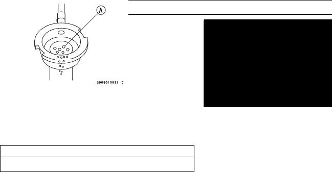
Air Cleaner Element Replacement
NOTE
○In dusty areas, the element should be replaced more frequently than the recommended interval.
○After riding through rain or on muddy roads, the element should be replaced immediately.

 WARNING
If dirt or dust is allowed to pass through into the throttle body assy, the throttle may become stuck, possibly causing an accident.
CAUTION
If dirt gets through into the engine, excessive engine wear and possibly engine damage will occur.
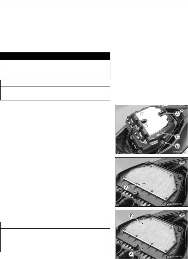
•Remove:
Secondary Fuel Hose (see Fuel Hose Replacement) Secondary Fuel Injector Connectors (see Nozzle Assy Removal in the Fuel System (DFI) chapter)
Connector [A] Screws [B]
Upper Air Cleaner Housing [C]
•Discard the air cleaner element [A].
•Install a new element [A] so that the screen side [B] faces upward.
CAUTION
Use only the recommended air cleaner element (Kawasaki part number 11013-0036). Using another air cleaner element will wear the engine prematurely or lower the engine performance.
•Install the upper air cleaner housing (see Air Cleaner Housing Assembly in the Fuel System (DFI) chapter).
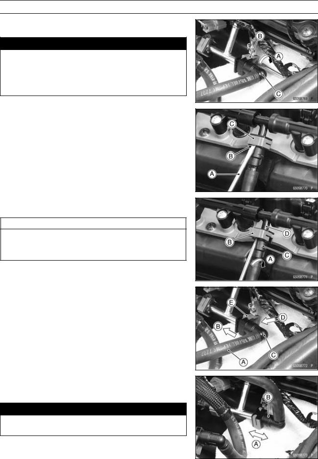
Fuel Hose Replacement
•Remove the fuel tank (see Fuel Tank Removal in the Fuel System (DFI) chapter).
PERIODIC MAINTENANCE 2-49
Periodic Maintenance Procedures
For Primary Fuel Hose (Fuel Tank Throttle Body Assy)
•Be sure to place a piece of cloth [A] around the fuel hose joint.
•Insert a thin blade screwdriver [B] into the slit [C] on the joint lock [D].
•Turn [A] the driver to disconnect the joint lock [B].
•Pull the fuel hose joint [C] out of the delivery pipe.

 WARNING
Be prepared for fuel spillage; any spilled fuel must be completely wiped up immediately.
When the fuel hose is disconnected, fuel spills out from the hose and the pipe. Cover the hose connection with a clean shop towel to prevent fuel spillage.
•Replace the fuel hose [A] with a new one.
•Run the fuel hose correctly (see Cable, Wire, and Hose Routing section in the Appendix chapter).
•Insert [B] the fuel hose joint [C] straight onto the delivery pipe until the hose joint clicks.
•Push [D] the joint lock [E].
•Push and pull [A] the fuel hose joint [B] back and forth more than two times and make sure it is locked and does not come off.

 WARNING
Make sure the fuel hose joint is installed correctly on the delivery pipe or the fuel could leak.
 If it comes off, reinstall the hose joint.
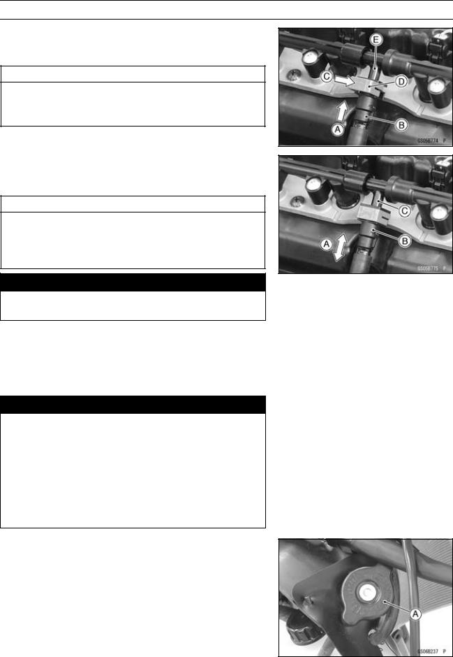
For Secondary Fuel Hose (Throttle Body Assy Nozzle
Assy)
•Be sure to place a piece of cloth [A] around the fuel hose joint.
•Insert a thin blade screwdriver [B] into the slit [C] on the joint lock [D].
2-50 PERIODIC MAINTENANCE
Periodic Maintenance Procedures
•Turn [A] the driver to disconnect the joint lock [B].
•Pull the fuel hose joint [C] out of the delivery pipe.

 WARNING
Be prepared for fuel spillage; any spilled fuel must be completely wiped up immediately.
When the fuel hose is disconnected, fuel spills out from the hose and the pipe. Cover the hose connection with a clean shop towel to prevent fuel spillage.
•Insert a thin blade screwdriver [A] into the slit [B] on the joint lock [C].
•Turn [A] the driver to disconnect the joint lock [B].
•Pull the fuel hose joint [C] out of the delivery pipe.
CAUTION
When pulling out the fuel hose joint, do not apply strong force to the delivery pipe [D] on the nozzle assy. The pipe made from resin could be damaged.
•Replace the fuel hose [A] with a new one.
•Insert [B] the fuel hose joint [C] straight onto the delivery pipe until the hose joint clicks.
•Push [D] the joint lock [E].
•Push and pull [A] the fuel hose joint [B] back and forth more than two times and make sure it is locked and does not come off.

 WARNING
Make sure the fuel hose joint is installed correctly on the delivery pipe or the fuel could leak.
 If it comes off, reinstall the hose joint.
PERIODIC MAINTENANCE 2-51
Periodic Maintenance Procedures
•Insert [A] the fuel hose joint [B] straight onto the delivery pipe until the hose joint clicks.
•Push [C] the joint lock [D].
CAUTION
When inserting the fuel hose joint, do not apply strong force to the delivery pipe [E] on the nozzle assy. The pipe made from resin could be damaged.
•Push and pull [A] the fuel hose joint [B] back and forth more than two times and make sure it is locked and does not come off.
CAUTION
When pushing and pulling the fuel hose joint, do not apply strong force to the delivery pipe [C] on the nozzle assy. The pipe made from resin could be damaged.

 WARNING
Make sure the fuel hose joint is installed correctly on the delivery pipe or the fuel could leak.
 If it comes off, reinstall the hose joint.
•Install the fuel tank (see Fuel Tank Installation in the Fuel System (DFI) chapter).
•Start the engine and check the fuel hose for leaks.
Coolant Change

 WARNING
To avoid burns, do not remove the radiator cap or try to change the coolant when the engine is still hot. Wait until it cools down. Coolant on tires will make them slippery and can cause an accident and injury. Immediately wipe up or wash away any coolant that spills on the frame, engine, or other painted parts.
Since coolant is harmful to the human body, do not use for drinking.
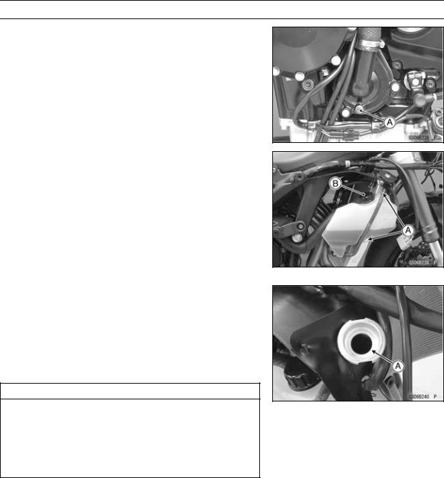
•Remove:
Upper Fairing Assembly (see Upper Fairing Assembly Removal in the Frame chapter)
Radiator Cap [A]
○Remove the radiator cap in two steps. First turn the cap counterclockwise to the first stop. Then push and turn it further in the same direction and remove the cap.
2-52 PERIODIC MAINTENANCE
Periodic Maintenance Procedures
•Place a container under the drain bolt [A] of the water pump cover.
•Drain the coolant from the radiator by removing the drain bolt.
•Remove:
Coolant Reserve Tank Mounting Bolts [A] Cap [B]
•Pour the coolant into a container.
•Tighten:
Torque - Coolant Reserve Tank Mounting Bolts: 6.9 N·m (0.70 kgf·m, 61 in·lb)
•Tighten the drain bolt with gasket.
Torque - Coolant Drain Bolt (Water Pump): 8.8 N·m (0.90 kgf·m, 78 in·lb)
•Fill the radiator up to the radiator filler neck [A] with coolant, and install the radiator cap.
NOTE
○Pour in the coolant slowly so that it can expel the air from the engine and radiator.
•Fill the reserve tank up to the “F” level line with coolant, and install the cap (see Coolant Level Inspection).
CAUTION
Soft or distilled water must be used with the antifreeze (see below for antifreeze) in the cooling system.
If hard water is used in the system, it causes scales accumulation in the water passages, and considerably reduces the efficiency of the cooling system.
Water and Coolant Mixture Ratio (Recommended)
Soft Water: |
50% |
Coolant: |
50% |
Freezing Point: |
–35°C (–31°F) |
Total Amount: |
2.5 L (2.6 US qt) |
NOTE
○Choose a suitable mixture ratio by referring to the coolant manufacturer’s directions.
PERIODIC MAINTENANCE 2-53
Periodic Maintenance Procedures
•Bleed the air from the cooling system as follows.
○Start the engine with the radiator cap removed and run it until no more air bubbles [A] can be seen in the coolant.
○Tap the radiator hoses to force any air bubbles caught inside.
○Stop the engine and add coolant up to the radiator filler neck.
•Install the radiator cap.
•Start the engine, warm it up thoroughly until the radiator fan turns on and then stop the engine.
•Check the coolant level in the reserve tank after the engine cools down.
 If the coolant level is lower than the “L” level line, add coolant to the “F” level line (see Coolant Level Inspection).
CAUTION
Do not add more coolant above the “F” level line.