

84 ANALYSIS OF DNA SEQUENCES BY HYBRIDIZATION
Figure 3.15 |
Renaturation kinetics actually seen for total |
human genomic |
DNA. The parameters plotted are the |
same as in Figure 3.14. |
|
phases to the reaction. About 10% of the DNA renatures almost immediately. It turns out |
|
|
|||||||||||||
this is very simple sequence DNA, some of which is self-complementary, and can rena- |
|
|
|
||||||||||||
ture by folding back on itself to make a hairpin. Other single-stranded components of this |
|
|
|||||||||||||
class form novel DNA ordered structures |
like some triplet-repeating |
sequences |
|
(see |
|
||||||||||
Chapter 13). About 40% of the DNA renatures 10 |
|
|
|
5 to |
10 |
6 times as |
fast as expected for |
||||||||
single-copy human DNA. This consists mostly of highly repeated sequences like the hu- |
|
|
|
||||||||||||
man |
Alu |
repeat. The |
effective |
|
C |
0 t1/2 |
for |
this DNA |
is |
about |
1. The |
remaining half |
of the |
||
genome does show the expected renaturation times for single-copy DNA. |
|
|
|
|
|
|
|
||||||||
|
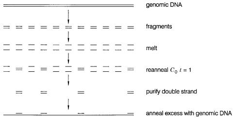
The repeated sequences that renature fast, but intermolecularly, are mostly interspersed |
|
|
||||||||||||
with single-copy DNA. Thus the length of the DNA fragments used in a renaturation ex- |
|
|
|
|
|||||||||||
periment will have a profound effect on the resulting products that one might purify at |
|
|
|||||||||||||
various times during the reaction. Repeats that come together fast will usually be flanked |
|
||||||||||||||
by single-copy sequences that do not correspond. If one purifies double stranded material, |
|
|
|||||||||||||
it will be a mixture of duplex and single strands, as shown in Figure 3.16. Upon further |
|
||||||||||||||
renaturation |
the dangling |
single strands |
will |
find their |
partners, |
but |
only |
at |
the |
cost |
|
||||
of generating a complex crosslinked network of DNA (Fig. 3.16 |
|
|
|
|
|
|
b). Eventually this will |
||||||||
act |
as such |
a barrier to |
diffusion that |
some |
of |
the |
strands will |
never find |
their |
mates. |
|
||||
Figure |
3.16 |
Effects of repeats on the structure of renatured DNA. |
(a) Initial complex between |
two DNAs |
that |
share partial sequence complementarity at a repeat. |
(b)Subsequent complexes |
formed at |
|
C 0 t’s sufficiently large to allow duplex formation between single copy sequences. |
|
COMPLEXITY 85
Figure 3.17 Blocking repeats by prehybridization with excess purified repeated DNA.
There are two solutions to this problem. One is to cut the genomic DNA down to sizes of |
|
|
|
|
|||||||||
a few hundred |
base pairs so that most single-copy |
sequences are essentially |
removed |
|
|
|
|||||||
from the repeats. The other alternative, if larger DNA is needed for a particular applica- |
|
|
|
||||||||||
tion, is to purify repeated DNA as small fragments and pre-anneal it |
at |
high |
concentra- |
|
|
|
|||||||
tions to single-stranded genomic DNA. This will block the repeat |
sites, |
as |
shown |
in |
|
|
|
||||||
Figure 3.17, and then the flanking single strands will be free to find their complements |
|
|
|
||||||||||
without network formation. |
|
|
|
|
|
|
|
|
|
|
|
||
One |
could |
ask why not cut genomic |
DNA down to tiny fragments for |
all reannealing |
|
|
|
|
|||||
or hybridization experiments. Indeed many current schemes for analyzing DNA with hy- |
|
|
|
|
|||||||||
bridization do use short oligonucleotide probes. These have one disadvantage. Their in- |
|
|
|
||||||||||
trinsic |
k2 is small. Recall that |
k2 really represents the |
nucleation |
reaction for |
duplex |
for- |
|
||||||
mation. This is the rate of formation of the first correct base pair |
that can |
zip into the |
|
|
|
||||||||
duplex structure. The number of potential nucleation sites increases as |
|
|
|
|
|
|
|
L, the length of the |
|
||||
strands. There is a second way in which length affects |
|
|
|
|
|
k2; this is the excluded volume of |
|
||||||
the coiled DNA single strands which retards the interpenetration needed for duplex for- |
|
|
|
|
|||||||||
mation. This depends on |
L 1/2 . When |
these two effects |
are combined, the |
result |
is that |
k |
2 |
||||||
depends on |
|
L1/2 . This discourages the use of small fragments for hybridization unless they |
|
||||||||||
|
|
|
|||||||||||
are available |
at very high concentrations. Ultimately, if too small |
fragments |
are |
used, |
|
|
|
||||||
there will also be an effect on the stability of the resulting duplexes. |
|
|
|
|
|
|
|
|
|
||||
COMPLEXITY
In thinking about DNA hybridization, it is useful to introduce the notion of DNA complexity. This is the amount of different DNA sequence present in a sample. For a DNA sample with repeated sequence and heterogeneities, the complexity is
i N i
m i
86 |
ANALYSIS OF DNA SEQUENCES BY HYBRIDIZATION |
|
|
||
where the sum is taken over every type of DNA species present; |
|
m i is the number of times |
|||
a species of |
size |
N i is repeated. The complexity will determine the |
hybridization |
kinetics |
|
of the slowest renaturing species in the sample. |
|
|
|||
HYBRIDIZATION ON FILTERS |
|
|
|||
In |
contemporary |
DNA work, hybridization of probes in solution to targets |
immobilized |
|
|
on filters is |
much |
more common than duplex formation in homogeneous solution. Two |
|
||
basic |
formats |
are |
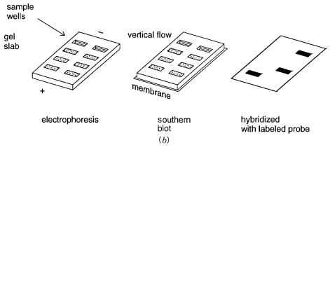
most frequently used; these are summarized in Figure |
3.18. In |
a dot |
blot, a sample of DNA from a cell, a viral plaque, or a sorted chromosome is immobilized (nominally) on the surface of a filter. It is anchored there by heating or UV crosslinking.
The |
exact mechanism of this immobilization is unknown, |
but it is important, |
especially |
for |
procedures in which the same filter is going to be subjected to many serial hybridiza- |
||
tions. Generally, the DNA sample is denatured by alkali or heating to temperatures near |
|||
100°C just before immobilization so that what is |
stuck to the filter |
is largely single- |
|
stranded material. A number of different types of filters are in common use; the most frequent are nitrocellulose and nylon.
Figure 3.18 |
Hybridization on filters. |
(a)A dot blot, in which DNA is spotted directly on a filter. |
(b)A Southern blot in which a filter replica is made of DNA after a gel-electrophoretic separation.
|
|
|
HYBRIDIZATION ON FILTERS |
87 |
In the Southern blot format, a mixture of DNA species is size-separated by electrophore- |
|
|||
sis on polyacrylamide or agarose gels (see Chapter 5). A replica of the gel-separated material |
|
|||
is made by transfer of the DNA through the plane of the separation gel to a parallel filter, as |
|
|||
shown in Figure 3.18. In this way the targets of the subsequent hybridization reaction can be |
|
|||
characterized by their electrophoretic properties. Several methods exist for transfer of the gel |
|
|||
sample to the filter. These include bulk liquid flow through the capillary network of a stacked |
|
|||
set of paper sheets, vacuum transfer of the fluid phase of the gel, pressure transfer of the fluid |
|
|||
phase of the gel, or electrophoretic transfer of the DNA by using electrodes perpendicular to |
|
|||
the plane of the original gel separation. All of these methods work. |
|
|
|
|
Several procedures exist where the transfer step can be avoided. One is prehybridiza- |
|
|||
tion of labeled probes to samples before electrophoresis. Another is drying the separation |
|
|||
gel and using it directly as a target for hybridization with radiolabeled probes. These pro- |
|
|||
cedures have never achieved the popularity of the Southern blot, mainly because they are |
|
|||
less amenable to successful serial probings. |
|
|
|
|
There are two basic advantages of |
filter hybridization |
compared |
with homogeneous |
|
phase hybridization. The target samples are highly confined. Therefore many different sam- |
|
|||
ples can be reacted with the same probe simultaneously. The second advantage is that the |
|
|||
original target molecules are confined in separate microscopic domains on the filter surface. |
|
|||
Thus they cannot react with each other. This largely avoids the formation of entangled ar- |
|
|||
rays, and it simplifies some of the problems caused by interspersed |
repeated DNA se- |
|
||
quences. Hybridization at surfaces does, however, produce some complications. The immo- |
|
|||
bilized target DNA is presumably attached to the surface at several places. This introduces a |
|
|||
number of obstacles to hybridization. The first of these is the potential for nonspecific attrac- |
|
|||
tion or repulsion of the probe DNA to the surface. More serious are the topological bound- |
|
|||
aries imposed by the points of surface-DNA attachment. These greatly reduce the effective |
|
|||
length of the target DNA. As measured by the |
relative kinetics of |
solution |
and immobilized |
|
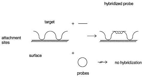
targets, the latter appear to have an effective length of only ten bases. The topological barriers will also affect the ability of DNA’s with nonlinear topologies to hybridize (Fig. 3-19).
Figure 3.19 Topological obstacles to filter hybridization as a result of frequent DNA attachment points.
88 ANALYSIS OF DNA SEQUENCES BY HYBRIDIZATION
Formation of double strands requires twisting of one strand around the other (see Box 2.1). Thus a circular probe (e.g., circular single-stranded DNA from a bacteriophage M13 clone) will be incapable of forming extensive double helix with an immobilized DNA target. An in-
genious use of this topological constraint to improve the detection of specific hybridization signals is the padlock probe approach described in Box 3.4.
BOX 3.4
PADLOCK PROBES
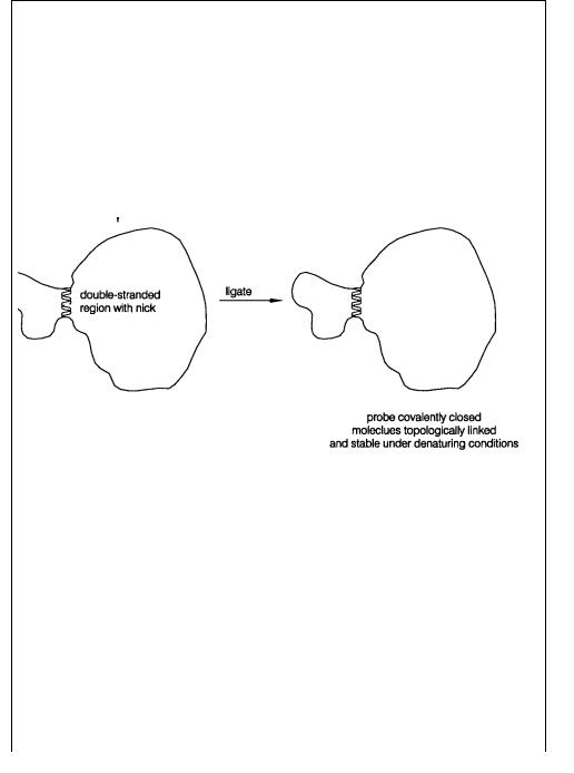
Ulf Landegren and his collaborators recently demonstrated that DNA topology can be used to improve the stringency of detection of correctly hybridized DNA probes. A schematic view of the procedure that they have developed is shown in Figure 3.20. Consider the hybridization of a linear single-stranded probe to a single-stranded circu-
lar target. The probe is specially designed so that it’s 3 |
- and 5 -terminal sequences are |
|
complementary |
to a continuous block of DNA sequence in the target. Probes like this |
|
can always be |
made synthetically (or they can be made by circularization with an arbi- |
|
trary flanking sequence by ligation and then cleavage within the probe sequence |
in a |
|
|
|
|
|
|
|
Figure 3.20 Example of the use of padlock probes. Here ligation is used to create a topologically linked probe-target complex in solution. The same approach can be used to link probes
onto DNA targets immobilized on filters. (Drawing provided by Fouad Siddiqi.)
(continued)
|
|
|
|
|
|
|
|
|
|
|
|
|
HYBRIDIZATION ON FILTERS |
89 |
|
BOX 3.4 |
(Continued) |
|
|
|
|
|
|
|
|
|
|
||
|
|
|
|
|
|
|
|
|
|
|
||||
|
way similar to the production of jumping probes described in Chapter 8). When the |
|
||||||||||||
|
probe |
is hybridized to |
the target, a substrate for DNA ligase is |
created. After |
ligation |
|
||||||||
|
the probe and target form a continuous stretch of double-stranded DNA. If this duplex |
|
||||||||||||
|
is greater than 10 bp in length, the probe and target strands are topologically |
linked. |
|
|||||||||||
|
Thus, as described in Box 2.1, although strong denaturants |
can melt the |
double- |
|
||||||||||
|
stranded region, the two resulting single strands cannot physically separate. |
|
|
|
||||||||||
|
When padlock probes are used in a filter hybridization format, a single-stranded cir- |
|
||||||||||||
|
cular target is not required. Because the target is fixed |
on the filter in multiple places, |
|
|||||||||||
|
as shown in Figure 3.19, each interior segment is topologically equivalent to circular |
|
||||||||||||
|
DNA. Thus padlock probes that are ligated after hybridization to such segments will |
|
||||||||||||
|
become topologically linked with them. This permits very stringent washing |
condi- |
|
|||||||||||
|
tions to be used to remove any probe DNA that is hybridized but not ligated, or probe |
|
||||||||||||
|
DNA that is nonspecifically adsorbed onto the surface of the filter. |
|
|
|
|
|
||||||||
|
|
|
||||||||||||
|
One variant on blot hybridization is the reverse dot blot. Here the probe is immobilized |
|
||||||||||||
on the surface while the labeled target DNA is introduced in homogeneous solution. This |
|
|||||||||||||
really does not change the advantages and disadvantages of the blot approach very much. |
|
|||||||||||||
Another variation on hybridization to blotted DNA samples is in-gel hybridization. Here |
|
|||||||||||||
DNA samples are melted and reannealed in hydrated gels, sometimes in between two dis- |
|
|
||||||||||||
tinct electrophoresis fractionations. Such hybridization schemes have been developed to |
|
|||||||||||||
specifically detect DNA fragments that have rearranged in the genome, by Michio Oishi, |
|
|||||||||||||
and to isolate classes of DNA repeats, by Igor Roninsen. |
|
|
|
|
|
|
||||||||
|
The kinetics of hybridization of DNA on filters or in dried gels (Fig. 3.21) can be de- |
|
||||||||||||
scribed by a variation of the same basic approach used for solution hybridization kinetics. |
|
|||||||||||||
The basic mechanism of the |
reaction is still bimolecular. At |
long distances |
the |
diffusion |
|
|||||||||
of probe |
DNA |
in solution |
toward the target |
will |
be more |
efficient than |
the |
diffusion |
|
|||||
of the immobilized target toward the probe, but these bulk |
motions do not really matter |
|
||||||||||||
that much to the rate. What matters is diffusion once the two DNAs are in each others’ |
|
|||||||||||||
neighborhood, and here we can think of them as still |
showing |
equivalent behavior. |
|
|||||||||||
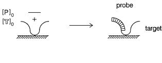
Usually, however, the relative concentrations of the probe and sample are very different. |
|
|||||||||||||
Most often the initial probe concentration, [P] |
|
|
0 , is much greater that the initial target con- |
|
||||||||||
centration [ |
T] , and we say |
that |
the |
probe |
drives |
the hybridization. The |
amount of free |
|
||||||
|
|
|
0 |
|
|
|
|
|
|
|
|
|
|
|
probe remains |
essentially |
constant |
during |
the reaction. |
Starting |
from |
the |
same basic |
|
|||||
second-order rate equation, we can write
d [T] k2[P ][T] k2[P ]0 [T] dt
Figure 3.21 Kinetics of hybridization of a probe to a target DNA immobilized on a filter at initial
concentrations of [ |
P ] and [ T] , respectively. |
|
|
0 |
0 |

90 ANALYSIS OF DNA SEQUENCES BY HYBRIDIZATION
Because [ |
P ] is constant, |
the resulting |
kinetics appear |
|
as |
pseudo–first |
order |
rather |
than |
|
|
|
|
|||||||||||||||||||||||||
|
|
0 |
|
|
|
|
|
|
|
|
|
|
|
|
|
|
|
|
|
|
|
|
|
|
|
|
|
|
|
|
|
|
|
|
|
|
|
|
second order. The rate equation can be integrated as |
|
|
|
|
|
|
|
|
|
|
|
|
|
|
|
|
|
|
|
|
|
|
|
|
|
|
|
|
|
|
|
|||||||
|
|
|
|
|
|
|
|
|
|
|
|
|
|
|
|
|
|
|
|
|
|
|
|
|
|
|
t |
|
|
|
|
|
|
|
|
|
|
|
|
|
|
|
|
|
d [T] k |
|
|
[P ] |
|
|
dt |
|
|
|
|
|
|
|
|||||||||||||||||||
|
|
|
|
|
|
|
[T] |
|
|
|
|
|
|
2 |
|
|
|
|
0 |
|
|
|
|
|
|
|
|
|||||||||||
|
|
|
|
|
|
|
|
|
|
|
|
|
|
|
|
|
|
|
|
|
|
|
|
|
|
|
|
0 |
|
|
|
|
|
|
|
|
|
|
from the initial concentration of |
target, |
[ |
|
|
|
|
|
|
|
|
|
T] , at |
time |
zero, |
to the |
concentration |
[ |
|
T], at |
|||||||||||||||||||
any later time |
t, to give |
|
|
|
|
|
|
|
|
|
|
|
|
|
|
|
|
|
0 |
|
|
|
|
|
|
|
|
|
|
|
|
|
|
|
|
|
|
|
|
|
|
|
|
|
|
|
|
|
|
|
|
|
|
|
|
|
|
|
|
|
|
|
|
|
|
|
|
|
|
|
|
|
|
|
|||
|
|
|
|
|
|
ln |
|
|
[T] |
|
k |
|
[P ] t |
|
|
or |
|
|
|
|
|
|
|
|||||||||||||||
|
|
|
|
|
|
|
|
|
2 |
|
|
|
|
|
|
|
|
|
||||||||||||||||||||
|
|
|
|
|
|
|
|
|
[T]0 |
|
|
|
|
|
|
|
|
|
0 |
|
|
|
|
|
|
|
|
|
|
|
||||||||
|
|
|
|
|
|
|
|
|
|
|
|
|
|
|
|
|
|
|
|
|
|
|
|
|
|
|
|
|
|
|
||||||||
|
|
|
|
|
|
|
[T] |
exp ( k |
|
[P |
] t) |
|
|
|
|
|
||||||||||||||||||||||
|
|
|
|
|
|
|
|
|
|
2 |
|
|
|
|
|
|||||||||||||||||||||||
|
|
|
|
|
|
|
[T]0 |
|
|
|
|
|
|
|
|
|
|
|
|
|
|
|
0 |
|
|
|
|
|
|
|
|
|||||||
|
|
|
|
|
|
|
|
|
|
|
|
|
|
|
|
|
|
|
|
|
|
|
|
|
|
|
|
|
|
|
|
|
||||||
The halftime of the reaction is defined as the time at which [ |
|
|
|
|
|
|
|
|
|
|
|
|
|
|
|
|
T]/[T] |
1 |
. This can be |
|||||||||||||||||||
written as |
|
|
|
|
|
|
|
|
|
|
|
|
|
|
|
|
|
|
|
|
|
|
|
|
|
|
|
|
|
|
|
|
|
|
|
0 |
2 |
|
|
|
|
|
|
|
|
|
|
|
|
|
|
|
|
|
|
|
|
|
|
|
|
|
|
|
|
|
|
|
|
|
|
|
|
|
|
|
|
|
|
|
|
|
|
t1/2 |
|
|
ln 2 |
|
|
|
|
|
|
|
|
|
ln 2 |
|
|
|
|
|
|
|
|
|||||||||||
|
|
|
|
|
|
|
|
|
|
|
|
|
|
k |
|
mC |
|
|
|
/ 2N |
|
|
|
|
|
|
|
|||||||||||
|
|
|
|
|
|
|
|
|
|
|
k |
2 |
[P |
] |
|
|
|
2 |
|
0 |
|
|
|
|
|
|
|
|
||||||||||
|
|
|
|
|
|
|
|
|
|
|
|
|
|
|
|
0 |
|
|
|
|
|
|
|
|
|
|
|
|
|
|
|
|
|
|
||||
where |
N |
is the genome size of the probe, |
|
|
|
|
|
|
|
|
C |
0 |
|
|
is the probe concentration in nucleotides, and |
|
m |
|||||||||||||||||||||
reflects any repeated sequences or heterogeneity. Note that if the probe is single stranded, the |
|
|
|
|
|
|||||||||||||||||||||||||||||||||
factor of two should be removed from the denominator. This allows us to write |
|
|
|
|
|
|
|
|
|
|
|
|
|
|
|
|
|
|
||||||||||||||||||||
|
|
|
|
|
|
|
C |
|
0 t1/2 |
2 ln 2 |
|
|
|
N |
|
|
|
|
|
|
|
|
|
|
|
|||||||||||||
|
|
|
|
|
|
|
|
|
|
|
|
|
|
|
|
|
|
|
|
|
|
|
||||||||||||||||
|
|
|
|
|
|
|
mk |
2 |
|
|
|
|
|
|
|
|||||||||||||||||||||||
|
|
|
|
|
|
|
|
|
|
|
|
|
|
|
|
|
|
|
|
|
|
|
|
|
|
|
|
|
|
|
||||||||
The equation is almost the same as the definition of |
|
|
|
|
|
|
|
|
|
|
|
|
|
|
|
|
|
|
|
|
C |
0 t1/2 for |
ordinary |
homogeneous so- |
||||||||||||||
lution hybridization. |
|
|
|
|
|
|
|
|
|
|
|
|
|
|
|
|
|
|
|
|
|
|
|
|
|
|
|
|
|
|
|
|
|
|
|
|
||
Occasionally the probe contains a trace radiolabel. The target is in great excess, and it |
|
|
|
|
|
|||||||||||||||||||||||||||||||||
drives the hybridization reaction. The above equations are |
exactly |
the |
same |
except that |
|
|
|
|
|
|||||||||||||||||||||||||||||
the role of target and probe are reversed, and |
|
|
|
|
|
|
|
|
|
|
|
|
|
|
mC |
|
|
0 /2N |
|
refers to |
target |
DNA. |
|
|
||||||||||||||
SENSITIVE |
DETECTION |
|
|
|
|
|
|
|
|
|
|
|
|
|
|
|
|
|
|
|
|
|
|
|
|
|
|
|
|
|
|
|
|
|
|
|
|
|
Hybridization frequently involves the detection of |
very small |
|
amounts |
|
of |
|
target |
DNA. |
|
|
|
|
|
|||||||||||||||||||||||||
Thus it is essential that the probe be equipped with a very sensitive detection system. The |
|
|
|
|
|
|||||||||||||||||||||||||||||||||
most conventional approach is to |
use |
a |
radiolabeled |
probe. |
|
|
|
|
|
|
|
|
|
|
|
|
|
|
|
|
|
|
|
32 P |
is |
the |
most |
common |
||||||||||
choice because its short half-life and high energy create a very intense radiodecay signal. |
|
|
|
|
|
|||||||||||||||||||||||||||||||||
The key to the use of |
32 P is to incorporate the |
label |
at very |
high specific activity at many |
|
|
|
|||||||||||||||||||||||||||||||
places in the probe. High specific activity means that many of the phosphorous atoms |
in |
|
|
|
|
|
|
|
||||||||||||||||||||||||||||||
the probe |
are |
actually |
32 P |
and not |
31 |
P. The most |
common |
way |
to |
do this is random prim- |
|
|
|
|||||||||||||||||||||||||
ing of DNA polymerase by short oligonucleotides to incorporate [alpha |
|
|
|
|
|
|
|
|
|
|
|
|
|
|
|
|
32 P]-labeled de- |
|||||||||||||||||||||
oxynucleoside triphosphates ([ |
|
|
32 P]dpppN’s) at many places in the chain. There is a trade- |
|
|
|||||||||||||||||||||||||||||||||

SENSITIVE DETECTION |
91 |
off between priming at too |
many places, which gives probes too short to |
hybridize well, |
|
||||||||||
and priming too infrequently, which runs the risk of not sampling the probe uniformly. In |
|
||||||||||||
principle, |
the highest |
specific |
activity |
probes would |
be |
made |
by |
using |
all |
four |
|||
32 |
|
|
|
|
|
|
|
|
|
32 |
P]dpppN’s are usually employed. |
||
[ P]dpppN’s. In practice, however, only one or two [ |
|
|
|
|
|
||||||||
Attempts to make even hotter probes are usually plagued by technical difficulties. |
|
|
|
||||||||||
The short half-life |
of |
32 P |
is |
responsible |
for |
its |
intense signal, but it also leads the |
||||||
major disadvantage of this detection system: The probes, once made, are rapidly decay- |
|
||||||||||||
ing. A second disadvantage of very high energy radioisotopes like |
|
|
|
|
|
32 P is that the decay |
|||||||
produces a track in a photographic film or other spatially resolved detectors that can be |
|
||||||||||||
significantly longer than the spatial resolution of the target sample. This blurs the pattern |
|||||||||||||
seen in techniques |
like |
autoradiographic detection of high-resolution DNA sequencing |
|
||||||||||
gels or in situ hybridization analysis (Chapter 7) of gene location on chromosomes. To |
|||||||||||||
circumvent this problem, lower-energy radioisotopes like |
|
|
|
|
|
|
35 S-labeled thio-derivatives of |
||||||
dpppN’s can be incorporated into DNA. However, to avoid the disadvantages of radioiso- |
|
|
|
||||||||||
topes altogether, many alternative detection systems have been explored. A few will be |
|
||||||||||||
discussed here. The principal concern with each is the ratio of the target signal to the |
|||||||||||||
background signal. The advantage of radioactive detection is that there is no intrinsic |
|||||||||||||
background from the sample (just a counting background due to cosmic |
rays and |
|
the |
|
|||||||||
like). This advantage disappears when chemical or spectroscopic detection methods are |
|
||||||||||||
used. |
|
|
|
|
|
|
|
|
|
|
|
|
|
After |
32 P, |
fluorescence |
is currently |
the |
most popular method |
for |
DNA detection, |
with |
|||||
chemiluminescent methods (Box 3.5) rapidly developing as strong alternatives. The ultimate sensitivity of fluorescent detection allows one to work with single fluorescent molecules. To do this, the dye label is pumped continually with an intense exciting beam of light, until it is finally bleached in some photochemical reaction. Clearly the more times the dye can absorb before it is destroyed, and the higher a fraction of dye decays that emit
a photon, the greater is the sensitivity. Both of these factors indicate that the ideal dye will have a fluorescence quantum yield (probability of de-excitation by light emission) as close to 1.0 as possible and a photodestruction quantum yield as low as possible.
BOX 3.5
CHEMILUMINESCENT DETECTION
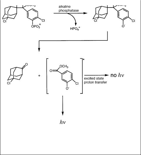
In chemiluminescence, a chemical reaction is used to generate a product that is in an electronically excited state. The product subsequently relaxes to the ground state by emitting a photon. The photon is detected, and the accumulation of such events can be used to make an image of the target. The advantage of this approach is that since there is no exciting light, there is no background of stray light from the exciting beam, nor is there any background of induced fluorescence from the filter or other materials used in the hybridization and blotting. An example of some of the chemical steps used in current chemiluminescent detection of DNA is shown in Figure 3.22. These methods have sensitivity comparable to those with the highest specific activity radioisotopes used, and they are more rapid. However, they often do not allow convenient serial re-
probings of the filter; this is a distinct disadvantage, and the possibility for multicolor detection, well developed with fluorescence, is not yet common with chemiluminescence.
92 ANALYSIS OF DNA SEQUENCES BY HYBRIDIZATION
BOX 3.5 (Continued)
Figure 3.22 Chemistry used in the chemiluminescent detection of DNA. An alkaline phos- phatase-conjugated probe is used for hybridization. Then it is presented with the substrate CDPstar tm . Upon dephosphorylation of the substrate by alkaline phosphatase, a metastable phenolate anion intermediate is formed that decomposes and emits light at a maximum wavelength of
466 nm.
While such single molecule detection is achievable, it is intrinsically noisy, as is any single molecule method. For this reason it is helpful to supplement fluorescent detection schemes by intermediate chemical amplification steps. Thus a single target molecule pro-
duces or is coupled to a large number of intermediates, and each of these in turn becomes the target for a fluorescence detection system. Two general schemes for chemical amplification are shown in Figure 3.23. Catalytic amplification uses an enzyme coupled to the
probe. After hybridization the enzyme is allowed to catalyze a reaction that releases a fluorescent or chemiluminescent product, or an intensely colored product. This must be done under circumstances where the products do not diffuse too far away from the site of
their creation; otherwise, the spatial resolution of the blot will be degraded. In stoichiometric amplification, potential diffusion problems are avoided by building up a physical
complex of molecules attached to the original probe. One way to accomplish this is by successive rounds of complementary polyvalent regents, sites, or ligands. This eventually generates a large network that can be coupled to many detector molecules.

SENSITIVE DETECTION |
93 |
Figure 3.23 Two types of chemical amplification systems. Catalytic amplification; stoichiometric amplification using two complementary multivalent reagents. D is a molecule that allows detection,
such as a fluorescent dye.
There are a number of different ligands and polyvalent reagents that have been widely |
|
|
|
|
|||||||||
used for nucleic acid analysis. Several of the reagents are illustrated in Figure 3.24. |
|
|
|||||||||||
Potentially the most powerful, in several respects, is the combination of biotin and strepta- |
|
|
|
|
|||||||||
vidin or avidin. Biotin can be attached to the 5 |
|
|
|
- or 3 -ends of nucleic |
acids, as |
discussed |
|||||||
earlier, or it can be incorporated internally by various biotinylated dpppN analogues. |
|
|
|
|
|||||||||
Streptavidin and avidin bind biotin with a binding constant |
|
|
|
|
K |
a |
approaching 10 |
15 under phys- |
|||||
iological conditions. The three-dimensional structure of streptavidin is known from two X- |
|
|
|
||||||||||
|
|
|
|
||||||||||
ray crystallographic studies (Figure 3.25). Since |
avidin |
and |
streptavidin are |
tetravalent, |
|
|
|||||||
there is a natural amplification route. After attaching single streptavidins to biotinylated |
|
|
|
|
|||||||||
probes, the three remaining biotin-binding sites on each protein molecule can be coupled to |
|
|
|
|
|
||||||||
a polyvalent biotinylated molecule such as a protein with several biotins. Then more strepta- |
|
|
|
|
|||||||||
vidin can be added, in excess; the network is grown by repeats of such cycles (Fig. 3.26 |
|
|
|
a ). |
|||||||||
In practice, for most nucleic acid applications, streptavidin, the protein product from the |
|
|
|
||||||||||
bacterium |
Streptomyces avidinii, |
is preferred |
over |
egg |
white avidin |
because |
it has |
an iso- |
|
||||
electric point near pH 7, which reduces nonspecific binding to DNA, and because it has no |
|
|
|
|
|
||||||||
carbohydrate, which reduces nonspecific binding to a variety of components and materials |
|
|
|
|
|
||||||||
in typical assay configurations. |
|
|
|
|
|
|
|
|
|
|
|
||
Most |
other |
stoichiometric |
amplification systems |
use monoclonal |
antibodies |
with |
|
|
|
|
|||
high affinity for haptens that can easily be coupled to DNA. Digoxigenin and fluorescein |
|
|
|
|
|||||||||
are the most frequent choices. After the antibody has been coupled to the hapten-labeled |
|
|
|
|
|||||||||
DNA, amplification can be achieved by sandwich techniques in which a haptenated sec- |
|
|
|
|
|
||||||||
ond antibody, specific for the first antibody, is allowed |
to bind, and then additional |
cy- |
|
|
|
|
|||||||
cles of monoclonal antibody and haptenated second antibody are used to build up a net- |
|
|
|
|
|||||||||
work. An example in the case of fluorescein is shown in Figure 3.26 |
|
|
|
|
|
b. Other haptens that |
|||||||
have proved useful for such amplification systems are coumarin, rhodamine, and dinitro- |
|
|
|
|
|
||||||||
phenyl. In |
all of |
these cases a |
critical concern |
is the |
stability of the network. While anti- |
|
|
||||||