

3D Game Programming All In One (2004)
.pdf388 Chapter 13 ■ Introduction to Modeling with MilkShape
Table 13.1 UVMapper OBJ Export Options Values
Value |
Option |
clear |
Export As Single Group |
set |
Export Normals |
set |
Export UV Coordinates |
clear |
Flip Texture (UV) Coordinates Vertically |
clear |
Flip Texture (UV) Coordinates Horizontally |
clear |
Reverse Winding Order |
clear |
Invert Normals |
clear |
Swap Coordinates Y and Z |
set |
Export Materials |
set |
Export UVMapper Regions |
clear |
Export Using Rotation Settings |
clear |
Don't Export Linefeeds (Mac compatible) |
clear |
Don't Compress Texture Coordinates |
Table 13.2 UVMapper BMP Export Options Values
Value |
Option |
512 |
Bitmap Size—Width |
512 |
Bitmap Size—Height |
clear |
Flip Texture Map Vertically |
clear |
Flip Texture Map Horizontally |
clear |
Exclude Hidden Facets |
21.Your texture should appear on the can in the 3D view, wrapped correctly.
22.If no texture appears, click in the 3D window to force an update.
23.If there is still no texture, make sure that you have the 3D window still set to Textured, by right-clicking in the 3D window and checking the menu.
Enhancing the Soup Can Model
Have a seat and stew on that for a while. When you are done, we'll carry on and start hammering at the soup can and improve the model.
How about we open the can up? The can model has a top and a bottom. We want to leave the bottom where it is and flip the top lid up.
First we need to separate the lid from the can.
1. Choose the Model tab and click Select.
Team LRN
MilkShape 3D |
389 |
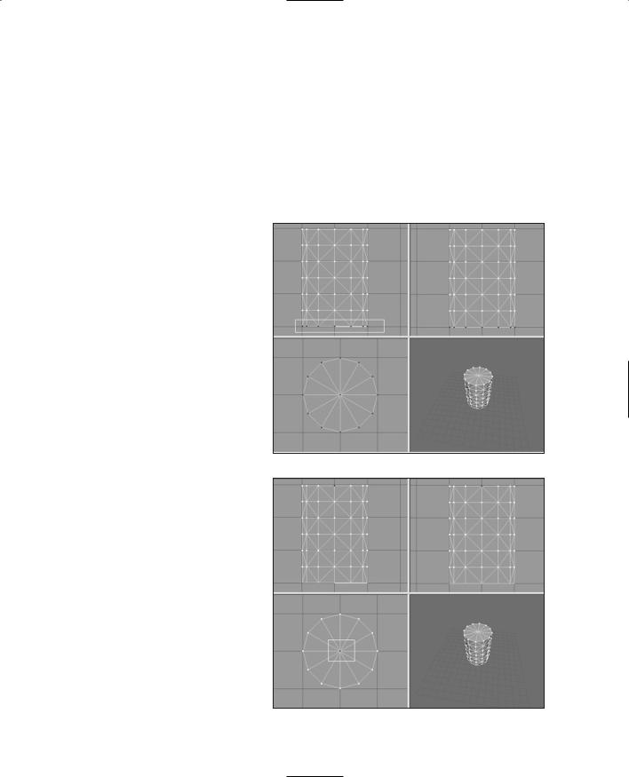
2.Click Vertex and select all the vertices at the bottom of the can, as shown in Figure 13.8. Use either the Side view or the Front view.
3.Choose Edit, Hide Selection. The dots of the vertices will disappear. This means that none of the vertices for the bottom face are selectable.
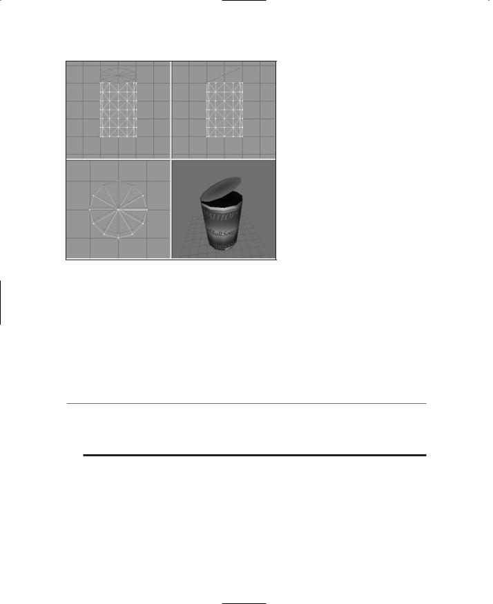
4.Now click Face. Make sure that By Vertex is selected.
5.In the Top view, select the vertex in the center of the can, as in Figure 13.9. Because you had hidden the bottom vertices, only the single center vertex for the top of the can has been selected. And because you are actually selecting faces by vertex, then all the top lid faces—and only those
faces—have been selected.
6.In the Groups tab, click Regroup. This will create a new mesh with only the faces from the top of the can. The mesh will be named "Regroup01". Rename this mesh to "lid" in the same manner that you did earlier when you renamed the cylinder mesh to "can".
7.Switch back to the Model tab. Your lid mesh should
still be selected.
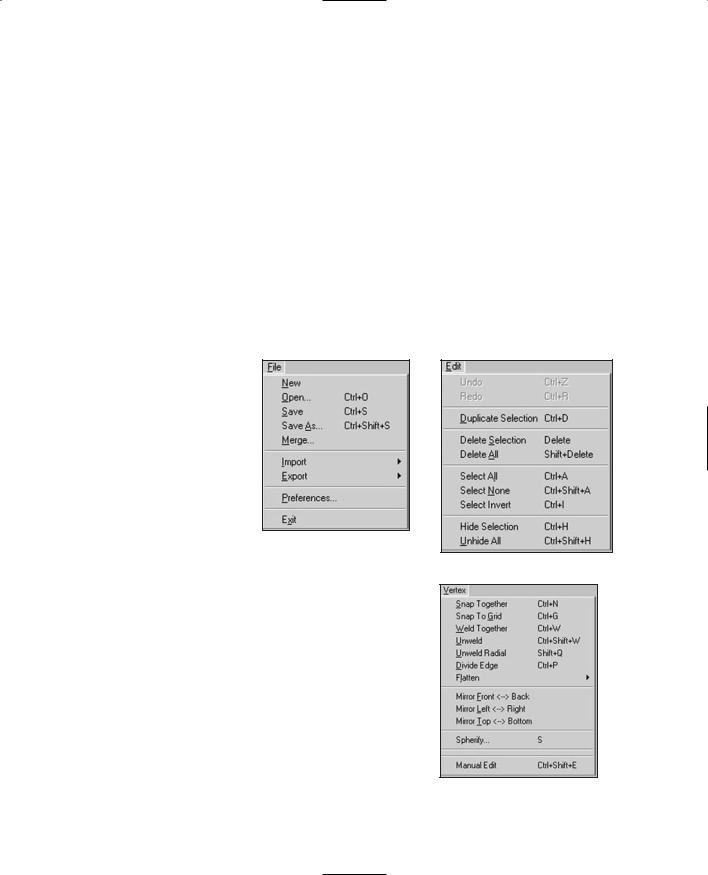
8.Click the Move button, and then click and drag in the Side view to move the lid up and to one side from the rest of the can.
9.Click the Rotate button, and then click and drag in the side window to rotate the lid as if you were bending the lid back (see Figure 13.10).
10.If necessary, repeat step 8 to position the lid properly. You might have to adjust it in one of the other views, depending on how you initially moved the lid.
Figure 13.8 Selecting the bottom vertices.
Figure 13.9 Selecting the center vertex.
Team LRN
390Chapter 13 ■ Introduction to Modeling with MilkShape
11.Choose the Groups tab and click Regroup. The lid faces will now be part of their own group.
12.Choose Edit, Duplicate Selection. Another copy of the lid will be made in exactly the same location as the original.
13.Select Face, Reverse Vertex Order. This will invert the normals of the lid's faces, making it viewable from the other direction. You will recall that the normal of a face is, in the simplest terms, the direction that a face is
Figure 13.10 The can with lid opened. |
facing. |
14.On the Groups tab, add the original lid to your selection by clicking on the first lid group.
15.Select Vertex, Weld Together. Now the original lid is viewable from one side, and the copy is viewable from the other. They now share the exact same vertices.
If you rotate your can in the 3D view, you'll see that your lid now has the lid part of the skin on both sides. You'll also notice that the inside of the can is black. This is because no faces are normalized to the interior, just as the lid at first did not have any faces normalized on the side.
t i p
You may be wondering why you didn't have to assign a material to the new faces you created with the Duplicate command. What happened is that when you grouped the original faces and the new faces together, the material that was assigned to the original lid faces were automatically assigned to the new group.
16.Repeat the above steps but this time create a set of faces for the can body that are normalized to the interior instead of the exterior, and then group them together. You can use your UV mapping and Paint Shop Pro skills to create a more realistic metallic interior to the can, instead of just repeating the exterior skin on the inside.
17.Save your work—you never know when a nice can of soup may be needed for dipping your towel in!
Team LRN
MilkShape 3D |
391 |
So, here we are. You've made a model of an object, using a couple of shape primitives. And you've learned how to make double-sided textures, rotate and move meshes (or groups), and assign skins. Feel free to explore your new capabilities. Poke around and try out the other primitives.
Menus
MilkShape can perform many more features and operations than what we've just gone over. In later chapters you'll learn how to make more difficult and challenging shapes, like player-characters, vehicles, and weapons. In this chapter we'll take a look at the program itself in more detail.
Most but not all of the menus have shortcuts assigned to the keys. Typically, the ones that are used the most do have shortcuts. If you want to add your own shortcut, you can use a plug-in to do that. We'll cover that when we discuss the Tools menu.
File
As in most Windows programs, operations in the File menu (see Figure 13.11) relate either to the creation and saving of files or to making global alterations to the current file's properties or contents. See
Table 13.3 for more detail.
Figure 13.11 The File menu.
Edit |
Figure 13.12 The Edit menu. |
The MilkShape Edit menu (see Figure 13.12) contains commands that assist the user when modifying models. It does not have Cut, Copy, or Paste but does offer commands in a similar vein for duplicating, hiding, and selecting objects. See Table 13.4 for more detail.
Vertex
You can perform a number of operations on vertices in a model. They are available through the Vertex menu (see Figure 13.13). In most cases you will need to ensure that you've selected only vertices in a model or at least have the
selection mode set to Vertex. See Table 13.5 for more detail. Figure 13.13 The Vertex menu.
Team LRN

392 Chapter 13 ■ Introduction to Modeling with MilkShape
|
Table 13.3 |
MilkShape File Menu |
|
|
Command |
Description |
|
|
New |
Creates a new blank workspace. If the current workspace is not empty, then |
|
|
|
the user is prompted to save changes or continue without saving. Only one |
|
|
|
workspace can be open at a time. |
|
|
Open |
Opens an existing MS3D formatted file using the standard Open dialog box. |
|
|
Save |
Saves the current workspace as an MS3D file, providing that the current |
|
|
|
workspace has a name. If the workspace is unnamed, then the command will |
|
|
|
behave like Save As. |
|
|
Save As |
Requires the user to specify a new file name under which to save the |
|
|
|
workspace contents. |
|
|
Merge |
Merges together two MS3D documents: the current workspace and another |
|
|
|
workspace selected from file. |
|
|
Import |
Presents a submenu of file import plug-ins. This command works like the Open |
|
|
|
command, once an import plug-in is selected, except that some plug-ins offer |
|
|
|
import options in a user dialog box. |
|
|
Export |
Presents a submenu of file export plug-ins. This command works like the Open |
|
|
|
command, once an import plug-in is selected, except that some plug-ins offer |
|
|
|
additional export-specific options in a user dialog box. |
|
|
Preferences |
Presents the Preferences dialog box. This allows the user to set definable global |
|
|
|
application attributes and behaviors. |
|
|
Exit |
Exits the MilkShape program. The user is prompted to save changes if there are |
|
|
|
any that haven't been saved. |
|
|
|
|
|
Table 13.4 MilkShape Edit Menu
Command |
Description |
Undo |
The workspace is reverted back to the state it was in before the last user |
|
operation. |
Redo |
The workspace is reverted back to the state it was in before the Undo |
|
operation. |
Duplicate Selection |
All selected objects are duplicated in place. This command selects the new |
|
duplicates and deselects the previously selected objects. |
Delete Selection |
The currently selected objects are deleted. |
Delete All |
All objects in the workspace regardless of their selection state are deleted. |
Select All |
All objects in the workspace are selected. |
Select None |
All objects in the workspace are deselected. |
Select Invert |
All objects that were selected are deselected, and all unselected objects are |
|
selected. |
Hide Selection |
The selected object is hidden from view. This operation can also be performed |
|
on groups using the Groups tab in the toolbox. |
Unhide All |
All objects in the workspace are shown. |
Team LRN
MilkShape 3D |
393 |
Table 13.5 MilkShape Vertex Menu
Command |
Description |
Snap Together |
Snaps all the selected vertices together. The middle point between all |
|
selected vertices becomes the new location for the vertices. |
Snap To Grid |
Moves all selected vertices to be in line with the smallest grid X, Y, and Z |
|
position (to see the smallest grid positions, zoom all the way in). The grid |
|
size can be changed using the File, Preferences menu. |
Weld Together |
Creates one vertex at a precise point where several vertices exist. Only |
|
selected vertices are welded together. This is the way you would join a |
|
seam of two or more abutting faces. |
Unweld |
Splits each selected vertex into multiple vertices. The number of vertices |
|
created depends on the number of faces the original individual vertices |
|
were bound to. For example, a vertex with three faces attached will be |
|
split into three vertices. |
Unweld Radial |
Is the same as Unweld but will also shift the unwelded vertices away from |
|
each other in a circular pattern. The vertices will move from the origin at |
|
which they were unwelded by half the distance from the origin to the |
|
nearest edge. |
Divide Edge |
Divides a face between two selected vertices into two faces. The procedure |
|
will only work with two vertices selected. This has no effect on vertices |
|
without any faces in common. |
Flatten |
Presents a submenu for the user to align all selected vertices to the same |
|
point on the X, Y, or Z plane. This is similar to Snap Together but it works |
|
on only one axis instead of all three. |
Mirror Front <--> Back |
Mirrors, or flips, the currently selected object along the Z-axis. |
Mirror Left <--> Right |
Mirrors, or flips, the currently selected object along the X-axis. |
Mirror Top <--> Bottom |
Mirrors, or flips, the currently selected object along the Y-axis. |
Spherify |
Calculates a bounding sphere and attempts to place the selected vertices |
|
on the surface of the sphere. It can be constrained in all three dimensions, |
|
and the bounds can be manually set. |
Manual Edit |
Allows the exact placement of one selected vertex with floating point |
|
accuracy in the X, Y, and Z planes. |
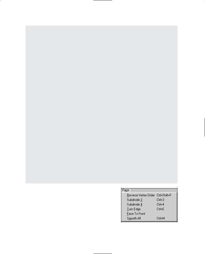
Face
The Face menu (see Figure 13.14) provides commands for manipulating triangles and faces in the workspace. See Table 13.6 for more detail.
Figure 13.14 The Face menu.
Team LRN
394 Chapter 13 ■ Introduction to Modeling with MilkShape
Table 13.6 MilkShape Face Menu
Command |
Description |
Reverse Vertex Order |
Changes the order of the vertex winding, which changes (negates) the |
|
normal of the face. This will turn a face inside or outside depending on its |
|
current vertex order. Counterclockwise vertex winding creates an outward |
|
face on an object. |
Subdivide 3 |
Divides each selected face by three, creating three faces out of one. |
Subdivide 4 |
Divides each selected face by four, creating four faces out of one. |
Turn Edge |
Is performed on two triangles with a common edge. The common edge is |
|
removed, and a new edge is created between the two vertices (one from |
|
each triangle) that weren't previously joined by an edge. |
Face To Front |
Is used on selected faces to change all vertex orders to counterclockwise, |
|
outward-facing vertex ordering, or winding. |
Smooth All |
Is used to smooth all faces after construction of parts of a model. |
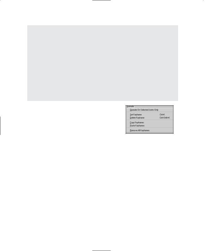
Animate
The Animate menu (see Figure 13.15) is used to manipulate animation frames in the model via the Keyframer. See Table 13.7 for more detail.
|
|
Figure 13.15 The Animate menu. |
|
|
|
|
|
|
Table 13.7 MilkShape Animate Menu |
||
|
Command |
Description |
|
|
Operate On Selected Joints Only |
When this menu item is toggled on (checked), then only the joints |
|
|
|
that are currently selected will have their pose data stored for the |
|
|
|
current keyframe. |
|
|
Set Keyframe |
This stores the pose of the skeleton to the current keyframe |
|
|
|
(whichever keyframe that's in the keyframe number box). |
|
|
Delete Keyframe |
This removes the stored skeleton pose from the current keyframe. |
|
|
Copy Keyframes |
This copies the skeleton pose from the current keyframe. In order for |
|
|
|
the copy action to perform correctly, the user must first select the |
|
|
|
skeleton in the keyframe to be copied from. |
|
|
Paste Keyframes |
This pastes the copied skeleton pose to the current keyframe. After |
|
|
|
the keyframe has been pasted, you need to immediately set the |
|
|
|
keyframe in order to preserve the skeleton pose. |
|
|
Remove All Keyframes |
This removes all stored skeleton poses at all keyframes in the |
|
|
|
animation timeline. This is effectively the same as deleting the |
|
|
|
animation. |
|
|
|
|
|
Team LRN
MilkShape 3D |
395 |
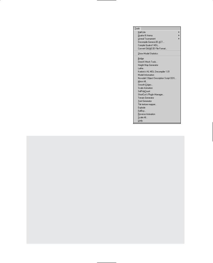
Tools
The Tools menu (see Figure 13.16) provides access to both built-in tools and user plug-in tools. The functions available are not the same as those available in the toolbox. This is a potential source of confusion. See Table 13.8 for more detail about the Tools menu.
Figure 13.16 The Tools menu.
Table 13.8 MilkShape Tools Menu
Command |
Description |
Half-Life |
This command contains several options used to create and save Half-Life models. |
Quake III Arena |
This command saves a Quake III control file to the directory you specify in the |
|
save window. |
Unreal Tournament |
This command contains options for creating male and female skeletons using |
|
the default Unreal Tournament skeleton configurations. |
Decompile Genesis- |
This command allows you to decompile an ACT model used by the Genesis 3D |
3D ACT |
engine. |
Compile Quake1 MDL |
This option will compile a Quake1 MDL file, used in the Quake 1 engine. |
Convert Old MS3D |
This command converts a file from an old version of the MilkShape 3D file File |
File Format |
format. The command can be used to change files created with MilkShape 3D |
|
versions 1.4.0 and earlier. |
Show Model Statistics |
Brings up a statistics window showing useful statistics, such as the number of |
|
faces and vertices in the workspace. |
Plug-Ins |
The list of plug-ins available is user-configurable using the Shortcut and Plug- |
|
In Manager. Not all plug-ins are distributed with MilkShape. See the |
|
MilkShape sidebar for descriptions of currently available plug-ins. To get the |
|
most up-to-date information about plug-ins, visit chUmbaLum sOft's Web site: |
|
http://www.swissquake.ch/chumbalum-soft. |
Team LRN

396 Chapter 13 ■ Introduction to Modeling with MilkShape
MilkShape Plug-Ins
There is quite a large list of MilkShape plug-ins that extend MilkShape's capabilities. For information about where to find them to download, tutorials about how to use them, and the names of the individual creators, see Appendix B, "Game Development Resources on the Internet." The plugins that were known at the time of this writing are listed; some plug-ins are import or export filters for different file formats and aren't included here, except for the Torque DTS Exporter, because we use it in this book (the Wavefront OBJ Importer and Exporter are built into MilkShape).
■ms2DTSExporter. This plug-in exports models, animations, and materials to DTS model format for use with the Torque Engine. This plug-in appears in the File, Export menu.
■msSelectionEditor. This plug-in edits the selection from a 3D view. There are a lot of options and you can read some detailed information about it here.
■msTimer. This plug-in lets you time how long you've been working on a certain model.
■msEdgeExtrude. This plug-in lets you extrude edges in addition to faces.
■msJointTool. This plug-in allows you to add joints in the middle of the hierarchy, unlink a joint from a hierarchy, and assign vertices to the closest joint (some kind of "Assign Mesh to Skeleton" tool).
■msSnap. This plug-in snaps not only to 1.0, it also snaps joints.
■msToolArray. This plug-in duplicates objects and then places the duplicates in 3D space according to user specifications.
■msVertexPlane. This plug-in is similar to the Vertex, Flatten command, except that it snaps selected vertices to a plane instead of a single point.
■msToolFatBoy. This plug-in will make your model fatter or thinner. This is useful for tweaking player and monster characters.
■msOperationMirrorAll. This plug-in will mirror everything about your model over the selected plane: bones, mesh, animation—everything.
■msToolReverseAnimation. This plug-in will reverse the order of the keyframes in whatever animation you have loaded.
■msToolScaleAll. This plug-in applies scale to all objects in the workspace at once.
■msSelPolyCount. This plug-in shows the selected polygon, vertex, and unique vertex counts, as well as how many polygons there are per group.
■msBridge. This plug-in creates a mesh connecting to previously independent meshes or groups.
■msTerGen. This plug-in can generate random terrains or import a bitmap file to use as a height map.
■msTextGen. This plug-in generates 3D objects in the form of text.
■msModelInfo. This plug-in provides more detailed information about a model than the Show Model Statistics command.
Team LRN
MilkShape 3D |
397 |
■msTileTextureMapper. This plug-in generates texture coordinates to geometry for tile textures (also known as seamless textures).
■msLathe. This plug-in takes flat geometry and turns it around the X-axis to build a 3D model.
You can install plug-ins by simply copying them to the MilkShape directory and then launching MilkShape. They will then appear under the Tools menu beneath Show Model Statistics.
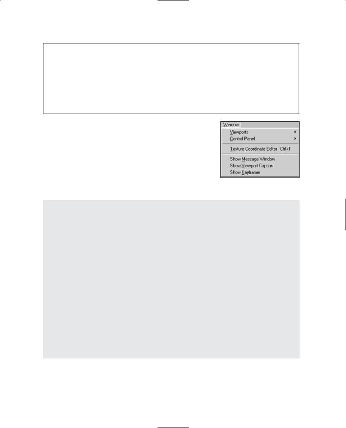
Window
The Window menu (see Figure 13.17) provides commands that determine what information is available in the MilkShape window and how it is displayed. See Table 13.9 for more detail.
Figure 13.17 The Window menu.
Table 13.9 MilkShape Window Menu
Command |
Description |
Viewports |
This command presents a submenu that allows you to pick an alternative |
|
viewport layout. The four-pane layout with three 2D views and one |
|
Perspective view is the default. |
Control Panel |
This command allows the user to set whether the toolbox frames appear |
|
on the left or right of the main window. The right side is the default. |
Texture Coordinate Editor |
This is for adjusting where textures appear on the model. Although useful, |
|
it is not as powerful or flexible as using a dedicated UV Unwrapping or |
|
Mapping tool like UVMapper. |
Show Message Window |
This option shows a script output window that holds the results of |
|
compiling various types of models for specific games. |
Show Viewport Caption |
This command shows details about the viewport it appears above. From |
|
left to right, the details are the view, the field of view, the near clipping |
|
plane, and the far clipping plane. |
Show Keyframer |
The Keyframer is the animation box along the bottom of the main |
|
window. It is used to create keyframe positions of bones and joints in a |
|
skeleton for animation. |
Team LRN