

3D Game Programming All In One (2004)
.pdf508 Chapter 17 ■ Making Structures
Figure 17.17 The finished bridge.
Figure 17.16 The Texture Browser.
Building a House
The bridge was nice and certainly useful. But one must admit that it's fairly simple. Of course, if you need a bridge you will probably make something more ornate.
In this section we will go a little bit farther and make something more complex: a house with a door opening and a window and internal lighting.
1.Launch QuArK and open the Torque Map Editor. Delete the default room and save the empty file as C:\QuArK 6.3\torque\tmpquark\maps\house.map.
2.Select the Cube brush and create a cube that measures 260 units in width by 360 units in length by 256 units in height. You can see the dimensions by hovering the cursor over the cube and looking in the lower-left corner of the Map Editor window.
3.Create a smaller brush in front of the first cube, as shown in Figure 17.19. This will be used to create the front stairs.
4.Select the new brush in the lowerleft window, and then right-click to get the pop-up menu and choose Stair. You will see your brush change into a staircase, as shown in Figure 17.20.
5.Select the large brush, right-click
to get the pop-up menu, and
Figure 17.18 The bridge in Emaga6. |
choose Make Hollow. Your large |
|
Team LRN
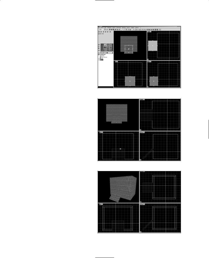
brush will now be a hollowed room and will look like the one in Figure 17.21.
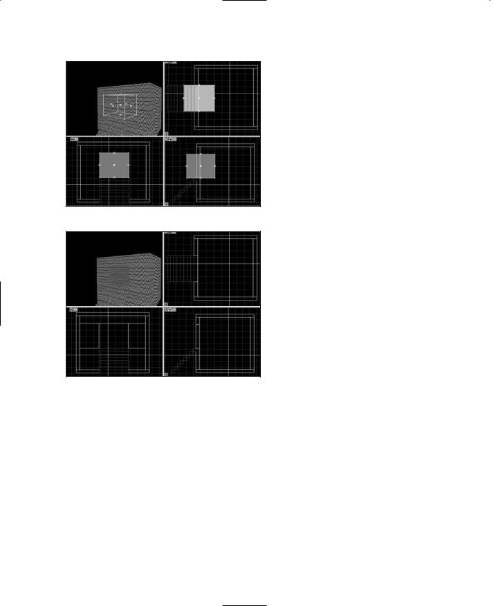
6.Create another brush and place it in the wall above the stairs, as shown in Figure 17.22. This brush will be used for an operation called a subtraction.
7.Ensure that the new brush is selected, right-click it, and choose Brush Subtraction. You will see a bunch of new lines appear in the wall in which the brush is embedded.
8.Select the Subtraction brush and press the Delete key to make it go away. You will see a hole in the wall now, as depicted in Figure 17.23. This is the doorway.
9.Using the texture assignment technique you learned in the earlier sections of this chapter, set the house's texture to concrete and the stairs' texture to 256_BrickA.
Now you have to add a special brush of a type known as an entity. Entities are constructs used when making maps that give special instructions to the map compiler about things it needs to do or understand when it goes about building the DIF version of the map for use in Torque.
You are going to create an entity called a portal. Portals tell Torque how to go about lighting the interior of the object when
Building a House |
509 |
Figure 17.19 The Stair brush.
Figure 17.20 The stairs.
Figure 17.21 The hollowed room.
Team LRN
510 Chapter 17 ■ Making Structures
Figure 17.22 The Subtraction brush.
Figure 17.23 The doorway.
there is an opening. By placing the portal in the doorway, you can tell Torque that it should not try to do its special interior lighting outside the door. You can also indicate whether or not Torque will allow external light to pass through the portal to the interior.
10.Locate the Entities panel in the upper-left portion of the Map Editor, and in it find the Torque Entities button. Click it.
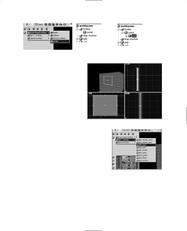
11.Choose Brush-based entities, portal, as shown in Figure 17.24.
12.An entry for the entity will appear in the Tree view in the lower-left portion of the Map Editor, as shown in Figure
13.Select the portal entity and then click the Cube button to create a Portal brush, as shown in Figure
17.26.A new brush will appear in the model—this is the Portal brush.
14.Reshape the Portal brush to be just a little larger than the doorway in width and height, and a little narrower than the doorway in thickness, as you can see in Figure 17.27.
15.In the Tree view, double-click the portal icon (not the poly icon that it contains). A small dialog box will appear; the bottom field is the parameter ambient_light setting for the portal. Choose passes through from the combo box.
16.Using the texture assignment technique you learned in the earlier sections of this chapter, set the portal's texture to NULL.
Next we are going to create another entity—a light entity. The process is similar to the portal entity at first, but a light entity is a point entity, not a brush entity, so things will be just a little different.
Team LRN
Building a House |
511 |
|
|
|
|
|
|
|
|
Figure 17.25 The portal |
|
|
|
|
|
||||
|
|
entity in the Tree view. |
Figure 17.26 The portal |
||
|
|||||
Figure 17.24 The portal entity. |
entity's brush in the Tree view. |
||||
17.As before, go to the Entities panel and find the Torque Entities button. Click it and choose light_*entities, light_omni, as shown in Figure 17.28.
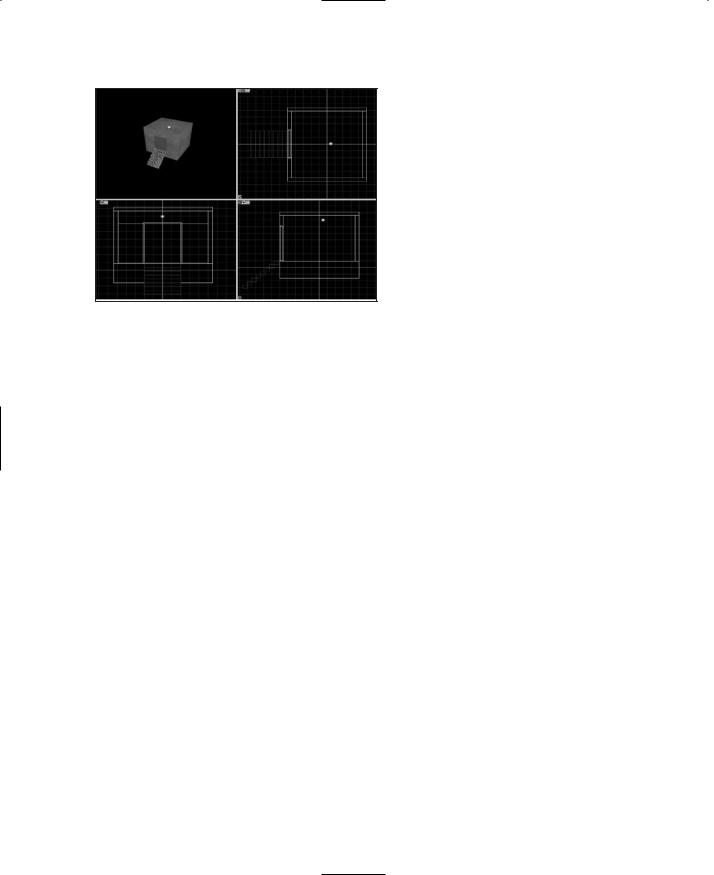
18.A new light entity will be created in the Tree view, and a small rendition of a light bulb will appear in your map. Move it up closer to the ceiling, as you can see in Figure 17.29.
19.Double-click the light_omni
entity in the Tree view to get to |
Figure 17.27 The portal in place. |
|
|
|
|
its settings. Ensure that alarm_type is set to nor- |
|
|
|
||
mal only. |
|
|
20.Save your work and export it using the methods you learned earlier in the Quick Start section.
21.Use UltraEdit to open the mission file for Emaga6, C:\aEmagaCh6\control\data\maps\ book_ch6.mis.
22.Locate this line:
interiorFile = "~/data/structures/newmap.dif"; |
Figure 17.28 The light entity. |
If the line doesn't exist in the file, then locate this one:
interiorFile = "~/data/structures/hovelb.dif";
Change whichever line you find to reflect your new structure as follows:
interiorFile = "~/data/structures/house.dif";
23.Run Emaga6 and check out your new house, which should be in front of you. Go on inside and see the effect the lighting has.
Team LRN
512 Chapter 17 ■ Making Structures
Moving Right Along
So, in this chapter you've learned yet another tool. QuArK is an extremely feature-complete tool for creating structures for Torque. You've built the two most common sorts of structures, an outdoor structure (the bridge) and a building with a lighted interior.
Your imagination is the only real limit here—castles, complex underground tunnel systems, factories, playgrounds,
Figure 17.29 The repositioned light entity. and just about anything else can be created with QuArK.
Normally, I would include a reference section for QuArK in this chapter. However, the program has so many features and options that the material is just too hefty to present in the chapter. Instead, I've included the QuArK reference in Appendix D.
In the next chapter, we'll take a look at how to make things for the game world environment.
Team LRN
chapter 18
Making the Game
World Environment
In many games, having a full suite of character models, buildings, trees, and other visual clutter is still not enough to accomplish the needed sense of immersion. There are a number of other aspects to the game world that come from the world around
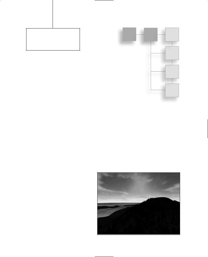
us that we often take for granted: the background sky, the appearance of water, the appearance of clouds in motion, and the terrain. Figure 18.1 is a nice serene picture of oceanside forested hills just after sunset. No, it's not a photograph—it's a screen shot from the game Tubettiworld being developed using the Torque Game Engine.
Now way back in Chapter 12 we covered terrains to a certain extent, so you probably have a reasonable sense of what is involved with creating terrains using a height map. In this chapter we will revisit terrains using the more labor-intensive method of manually building up a terrain with the in-game editor. We'll get into that at the end of this chapter.
First, however, we will visit sky, clouds, and water—the environmental triad of computer game ambience.
Skyboxes |
|
|
When you are tasked to create a 3D |
|
|
game that offers unrestricted player |
|
|
movement in unlimited vistas, you will |
|
|
need to come up with ways to provide |
|
|
that open, outdoors perception. |
|
|
A technique that works well is to pro- |
|
|
vide a static background sky that con- |
|
|
tains elements of the sky that we often |
Figure 18.1 A serene scene. |
513 |
|
|
Team LRN
514Chapter 18 ■ Making the Game World Environment
take for granted, like clouds, and a color gradient that changes as you move farther away from the horizon. We do this using a construct known as a skybox.
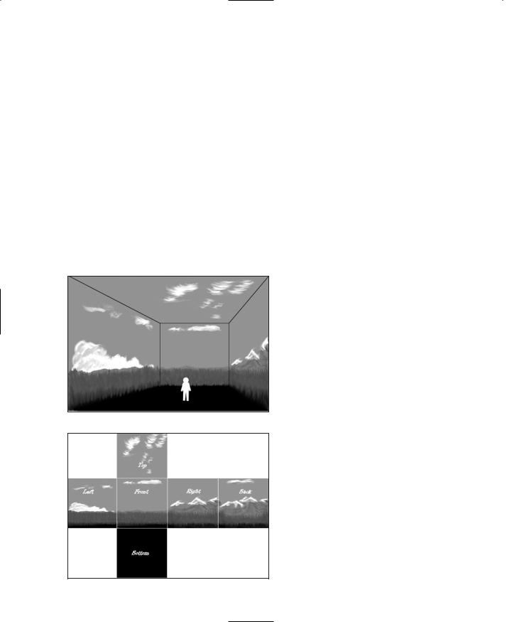
A skybox is a cube that surrounds the game player. The player stands inside the box, and no matter which way he turns, he will see some part of the box as long as it isn't obscured by other in-game objects. The box never rotates, and the sides are always the same distance away from the player no matter how far or how fast he moves. Because of the way the images on the faces of the skybox are created, the player does not have the feeling that he is inside a big cube. The skybox images are on the inside faces of this cube, as you can see in Figure 18.2. The back view has been left out to help illustrate the point.
When using skyboxes, we treat them as if they are infinitely large. Only objects that the player can never reach will look correct, like clouds in the sky or distant mountains. If you limit a player's movement to just viewing from a fixed location, you could even use a skybox for nearby scenery.
Figure 18.3 shows an exploded view of the skybox images and how they relate to each other. Note that the image for the bottom is a black field. If you were depicting an area
Figure 18.2 A pictorial skybox.
Figure 18.3 An exploded skybox.
with a usable view in that direction, you would of course include an appropriate image.
To create the illusion that the player is embedded in a large and seamless world, there are two things that you must get right when creating a skybox: seamless, matching adjacent edges and correct perspective.
The edge matching issue is one we are already familiar with from previous texture endeavors.
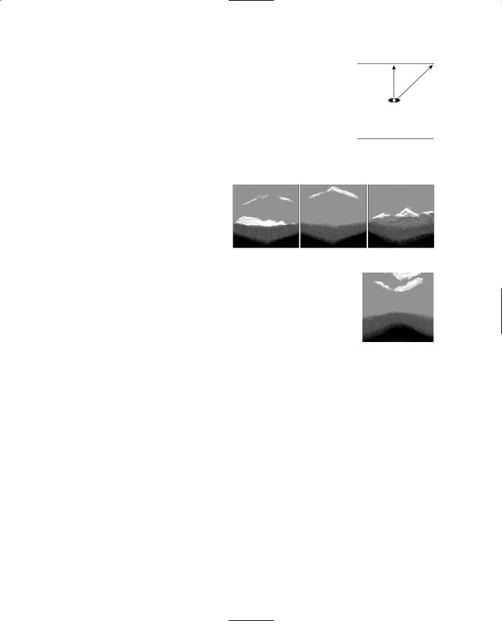
The perspective issue is a little less obvious when you first consider making skyboxes—but take a look at Figure 18.4. Remember that the skybox is always the same distance away from the player, and the orientation is fixed. The front face, if it happens to be facing north, will always face north, no matter which way the player is facing or looking. This causes a visual problem when viewing the images on the skybox faces.
Team LRN
|
|
|
Skyboxes |
515 |
The image areas that are on the face closest to the player will |
|
|
|
|
|
|
|
||
appear larger than the portions of the image nearest the corners, |
|
|
|
|
because the corners are farther away. Figure 18.5 simulates what |
|
|
|
|
that would look like. |
|
|
|
|
In order to remove the distortion when the image is viewed in game, |
|
|
|
|
we need to distort its appearance outside the game environment in |
|
|
|
|
Figure 18.4 |
|
|||
such a way that when the perspective comes into play in game, the |
|
|||
image looks natural. Figure 18.6 shows such a predistorted image. |
Skybox edge |
|
||
distances. |
|
|||
|
|
|
||
Each of the six square skybox images |
|
|
|
|
should be created with the same reso- |
|
|
|
|
lution. The most common resolution |
|
|
|
|
to use is 256 by 256 pixels. The higher |
|
|
|
|
the resolution, the better the skybox |
|
|
|
|
will look in most cases, but there is a |
|
|
|
|
limit beyond which higher skybox Figure 18.5 Distorted image. |
|
|
|
|
image resolution doesn't help the |
|
|
|
|
|
|
|
||
appearance. Because we are always worried about memory used and |
|
|
|
|
processing time consumed, we want to make sure we don't go higher |
|
|
|
|
than the maximum. If you are interested in using larger skybox |
|
|
|
|
images, there is a way to calculate the maximum resolution to use as |
|
|
|
|
your upper limit, using this mathematical formula: |
|
|
|
|
|
|
|
|
|
maxSkyboxResX = maxScreenResX * 1/tan(FOV/2) |
|
Figure 18.6 |
|
|
maxSkyboxResY = maxScreenResY * 1/tan(FOV/2) |
|
Predistorted |
|
|
image.
The basic concept is that the smaller the Field of View (FOV), the
higher the resolution you will need for the skybox. This is because as the FOV gets smaller, you are looking farther and at a smaller portion of the skybox image. This smaller portion fills the view, and therefore the pixels are larger. Typical first-person point-of-view games use a 90-degree FOV and often have a 60-degree (or even smaller) zoomed-in view for sniper scopes or binoculars.
For example, if our screen resolution is 800 by 600 pixels and our FOV is 90 degrees, then applying our formula yields this:
maxSkyboxResX = 800 * 1/tan(90/2)
maxSkyboxResX = 800 * 1/1
maxSkyboxResX = 800
It also follows that we don't need to recompute the Y resolution because it will scale proportionally. So for this 800 by 600 pixel display with a 90-degree FOV, the highest resolution we should use for the skybox images is 800 by 600 pixels, by happy coincidence!
Team LRN
516 Chapter 18 ■ Making the Game World Environment
However, if we want to know the deal for the 60-degree FOV that our player's binoculars provide, we need to recompute that value as follows:
maxSkyboxResX = 800 * 1/tan(60/2) maxSkyboxResX = 800 * 1/ 0.57735 maxSkyboxResX = 800 * 1.732 maxSkyboxResX = 1386
For the Y resolution, the value is 1,039. So if you decide to create a high-resolution skybox, you should probably go with nothing larger than 1,280 by 1,024 pixels. (Most games, including Torque, need the image resolution values to be powers of two.)
Personally, I would go with 1,024 by 1,024 as a reasonable compromise for a maximum resolution. These dimensions would apply to all of your skybox panels in a given skybox. The size you eventually choose for your game will in the end be a judgment call, but by using the previous calculations, not just a hopeful stab in the dark.
Creating the Skybox Images
As with other texture-related issues, there is always the question of where to obtain source material. Once again, you have the option of creating your own by using a digital camera or a camera and scanner combination or by simply drawing your own images.
In this section I will walk you through drawing some clouds on the horizon for your sky- box—this is a common sunny-day sort of scene. Low cumulus clouds in the distance peek just above the horizon, all around you.
1.Open Paint Shop Pro and create a new image by selecting File, New. Fill in the dialog box with 256 for both the height and width of the blank image. Make sure that the color depth is set to 16 million colors (24 bit).
2.Save this blank file as C:\aEmaga6\control\data\maps\front.png.
3.Select the Fill tool.
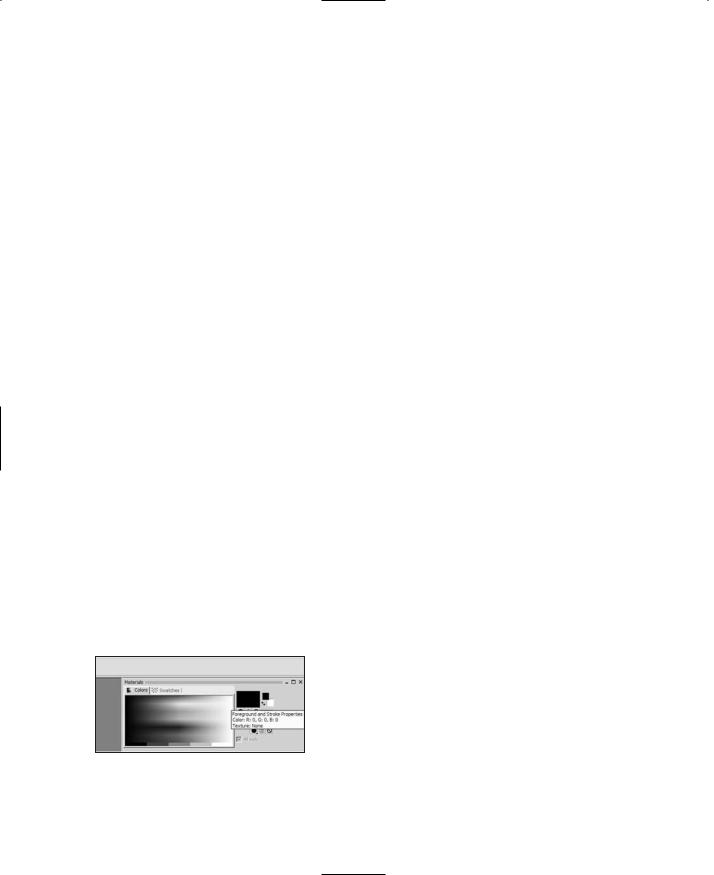
4.Over in the Materials palette, select the Foreground and Stroke Properties check box, just to the right of the color picker (see Figure 18.7).
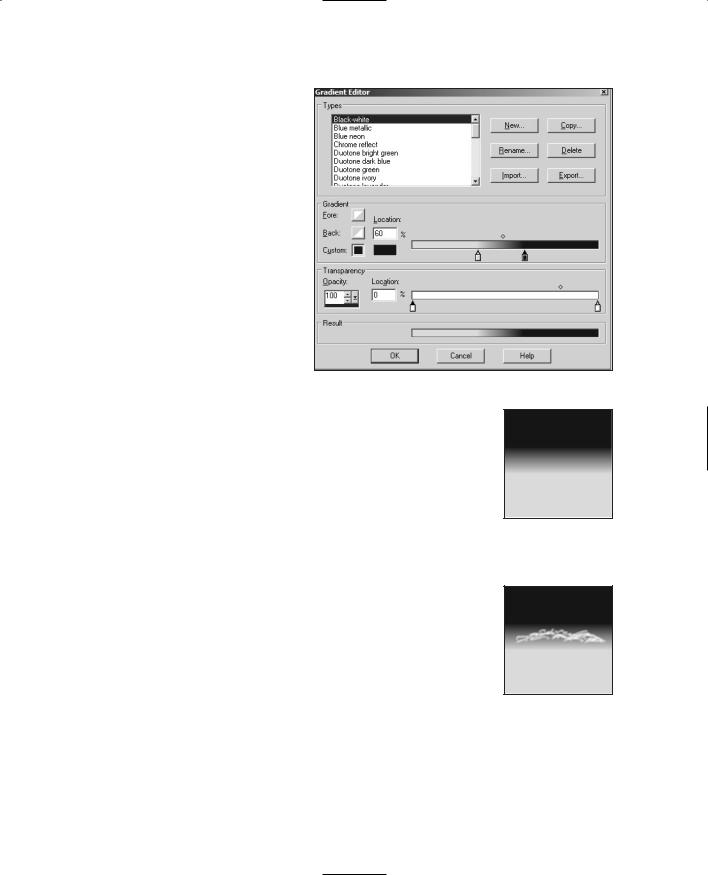
5.When the Materials dialog box opens, click the Gradient tab.
6.Make sure the value in the Angle window is set to 0, and then click the Edit button.
7.Set the Gradient scale to have two color mark-
Figure 18.7 Foreground and Stroke
Properties check box.
ers (they look like little pens) on the bottom side of the scale to approximate the settings shown in Figure 18.8. Do the same for the range modifier (the little diamond on the top).
Team LRN
Skyboxes 517
8.Click the leftmost color marker, and then click in the color picker window to its left.
9.In the Color dialog box, enter the RGB values as 215, 215, 255, respectively.
10.In the same manner, set the right-hand marker to 0,0,192.
11.Click OK and then OK again to close the windows and accept the settings.
12.Now click the Fill tool in the image to get a gradient like that shown in Figure 18.9.
13. Change the Foreground and Figure 18.8 The Gradient scale. Stroke Properties check box
out of gradient mode and into color mode. Then use the Eyedropper to set its color to pure white.
14.Next select the Air Brush tool and set the size to 8, the Hardness and Density to 70, and the Opacity to 15.
15.Now draw some cloudlike shapes between about half and two-thirds of the way from the top of the image so that you get something like Figure 18.10.
16.Create three more versions of this image, naming the others "left.png", "right.png", and "back.png" in the same place you saved front.png. Go ahead and make each one different in its own way, if you like.
17.Make a fifth image that is solid blue, with RGB values of 0,0,192. This color matches the darkest blue in the gradient we made. Name this file "top.png".
18.Make the sixth and final image and fill it in with black. Name this one "bottom.png".
Now it's time to test out your images.
Figure 18.9
Image with gradient.
Figure 18.10
Some clouds.
19.Locate the file in your Emaga6 map folder called C:\aEmaga6\control\data\maps\sky_day.dml. Make a copy of this file in the same directory and name the copy "sky_book.dml".
Team LRN