

3D Game Programming All In One (2004)
.pdf458 Chapter 14 ■ Making a Character Model
Table 14.3 Animation Sequence Material Names
Torque Sequence Name |
Sequence Material Name |
root |
seq:root=1-30,fps=10,cyclic |
run |
seq:run=31-70,fps=15,cyclic |
head |
seq:head=71-72 |
headside |
seq:headside=73-74 |
look |
seq:look=75-76,fps=15 |
die1 |
seq:die1=80-120 |
Exporting the Model for Torque
In the next section of this chapter, we will look at the Torque DTS Exporter for MilkShape, but for now we'll just use it in a fundamental way to get our model to work in Torque.
1.After saving your work, choose File, Export, Torque Game Engine DTS. You will see the Torque Game Engine (DTS) Exporter dialog box appear.
2.We're going to take the defaults, but we should make sure they are correct. You want to have Export animation and Export material information selected, and Collision Mesh should be set to None (Torque handles player collision internally). Click OK when ready.
3.Save your DTS file as C:\3DGPAi1\resources\ch14\myhero.dts.
That was pretty painless. Now let's make sure the model works! We'll dust off the old Torque Show Tool we used in Chapter 9 and check out the model.
1.In Windows Explorer browse your way to C:\3DGPAi1 and launch the Show Book Models shortcut.
2.Click Load Shape.
3.Find RESOURCES/CH14/myhero.dts, choose it, and click Load.
4.The model should appear in the center of the screen, facing away from you.
5.Use the navigation keys (described in Chapter 9 in Table 9.1) to rotate the model and bring it closer to you. You should notice that it is already performing the idle animation (root).
6.Click Thread Control. A window will appear on your screen, probably at the lower right. Drag it to the upper-left corner, or wherever is most convenient.
7.Click Run in the Sequences list. The character should start the run sequence.
8.Check out the other sequences, but remember, the ones that don't cycle are going to run just once and will stay at the last frame. You can use the Transitions button to adjust the transition speeds so that you can check to see if you are getting your desired results.
Team LRN
The Torque DTS Exporter for MilkShape |
459 |
9.If necessary, go back to your model in MilkShape and make adjustments to your animations, and then come back here to check them out.
Good job! The rule of thumb is, if it works in the Show Tool, it will work in the game, because the Torque Engine is behind both.
You now have an animated Hero character to use in your game! And it really isn't that difficult. If you are even a halfway decent artist and have a good eye, I'm sure your model and animations are much better than mine.
The next section provides some detail into the workings of the DTS Exporter for the Torque Engine. With its help, you should take some time to fiddle with settings and different animations and add your own animation sequences.
The Torque DTS Exporter for MilkShape
The Torque DTS Exporter is included in your C:\3DGPAi1\resources\tools directory and is called ms2dtsexporter.dll. Copy this file into your MilkShape directory, C:\Program Files\MilkShape 3D 1.6.6, and then restart MilkShape. The name of the MilkShape folder changes from version to version, so watch out for that. The exporter shows up under the File, Export menu.
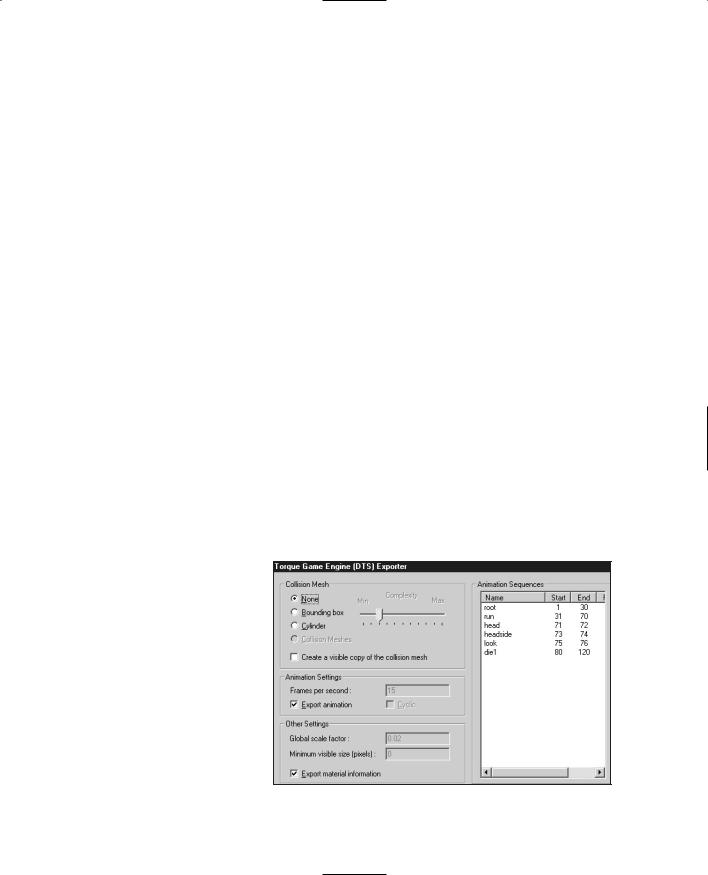
The Torque Game Engine (DTS) Exporter Dialog Box
The Torque Game Engine (DTS) Exporter dialog box (see Figure 14.94) has three groups of options, none of which normally need to be set. Option settings are not saved, so you rarely use this dialog box for more than just a means to double-check your option values. The recommended approach is to set options using special materials.
Collision Mesh
The exporter allows you to create as many collision meshes as you want. Each collision mesh must be named "Collision"; if you have three collision meshes, they will all be named "Collision". If you do not have a collision mesh defined, you may have the exporter create one for you
as either a box or a cylinder. Figure 14.94 Torque Game Engine (DTS) Exporter dialog box.
Team LRN

460Chapter 14 ■ Making a Character Model
You can also manually select an existing mesh. Player-characters don't need a collision mesh at all.
Select the Create a visible copy of the collision mesh check box to make the mesh visible as well as collidable.
Animation Settings
The Animation Settings group displays the global values for the Animations.
■Frames per second. This field indicates at what speed the Torque Engine should play at the animations. This field can be set using an Export Options material and applies globally to all animation sequences. This does not affect the number of keyframes; it simply sets the rate at which they will be played.
■Export animation. If the shape is animated, but no animation sequence has been defined for it, then this field contains the name that will be assigned to it. The sequence will cover the full timeline. This feature is useful for simple models with a single animation sequence.
Other Settings
The Other Settings group contains miscellaneous settings values.
■Global scale factor. The global scale factor is the amount by which the shape is scaled when it is exported. The default scale factor is 0.1, but this field can be changed to any value set using an Export Options material.
■Minimum visible size (pixels). If the projected screen size of the bounding radius of the shape drops to the minimum visible size, the shape will no longer render. This is normally used to switch between different detail levels, and it's recommended that you leave this at the default value: 0.
■Export material information. You may disable the exporting of material information (not recommended) by clearing the Export material information check box.
Special Materials
MilkShape does not directly support a number of Torque Engine features, so the tool has been extended through the use of several clever uses of existing MilkShape features, based on material and mesh names. These are described more fully in the following sections, but they basically fall into two categories: mesh flags embedded in the mesh's name and specially named materials that are used to declare animation sequences and exporter options.
Special materials are materials that are not exported as real materials but are instead used only to store information in the MilkShape file. These materials are processed by the exporter but are not written into the DTS file.
Team LRN

The Torque DTS Exporter for MilkShape |
461 |
Export Options
Materials with special names can be used to set several export options. These materials are ignored during export and are solely used to set options.
Option materials are named as follows:
opt: option, option, ...
All other properties of the material are ignored. Table 14.4 lists the available options.
|
Table 14.4 |
Export Options |
|
|
Option |
Description |
|
|
scale=n |
The global shape scale factor, where n is a floating point value. The default scale |
|
|
|
value is 0.1. |
|
|
size=n |
The global minimum visible pixel size. The default is 0. |
|
|
fps=n |
The global default frames per second value for animations. Each animation |
|
|
|
sequence may set this value, but if it's not defined by the sequence, this default |
|
|
|
value is used. |
|
|
cyclic |
The global default animation looping flag. Each animation sequence may set this |
|
|
|
value, but if it's not defined by the sequence, this default value is used. |
|
|
|
|
|
There may be more than one option material. If the same options are set on multiple materials, then the last one in the material list is the value used. Here are a couple examples of valid material names:
opt: fps=10, cyclic
opt: scale=0.1
Material Option Flags
Material attributes can be set using the MilkShape Shininess and Translucency sliders as well as by embedding additional flags in the material name.
Environment mapping can be controlled for the model by use of the Shininess slider—it's the one on the left-hand side. Setting the slider to any value but 0 will enable environment mapping for the texture. Note that the texture you are using must have an alpha channel, which will be used to control the per-pixel shininess of the texture. Any value of the slider other than 1.0 or 0.0 will be ignored.
You can enable translucency by setting the MilkShape Translucency slider—this is the slider on the right-hand side. Setting the slider to any value other than 1.0, which is to the far right, will enable translucency for the texture. The texture you are using must have an
Team LRN

462 Chapter 14 ■ Making a Character Model
alpha channel, which will be used by the Torque Engine to control the per-pixel translucency of the texture. Any value of the slider other than 1.0 or 0.0 will be ignored.
Options that are embedded in the material name follow this format:
name: flag, flag, ...
where the : and flags are optional. Table 14.5 shows which flags are available.
|
Table 14.5 |
Material Option Flags |
|
|
Flag |
Description |
|
|
Add |
Enables additive transparency. |
|
|
Sub |
Enables subtractive transparency. |
|
|
Illum |
Enables self-illumination (lighting doesn't affect it). |
|
|
NoMip |
Disables mipmapping. |
|
|
MipZero |
Sets the "MipMapZeroBorder" flag. |
|
|
|
|
|
A self-illuminating additive material could be called as follows:
Flare: Add, Illum
Mesh Option Flags
Meshes can have additional flags embedded in the mesh (or group) name. The mesh name follows this format:
name: flag, flag, ...
where the : and flags are optional. Table 14.6 shows which flags are available.
|
Table 14.6 |
Mesh Option Flags |
|
|
Flag |
Description |
|
|
Billboard |
The mesh always faces the viewer. |
|
|
BillboardZ |
The mesh faces the viewer but is only rotated around the mesh's Z-axis. |
|
|
ENormals |
This flag encodes vertex normals. It is deprecated and should not be used unless |
|
|
|
you know what you're doing. |
|
|
|
|
|
Team LRN

The Torque DTS Exporter for MilkShape |
463 |
Here are some legal mesh or group names:
■leaf
■leaf: Billboard
■leaf: BillboardZ
By default, meshes do not have any flags set.
Animation Sequences
MilkShape only provides a single animation timeline, but the Torque Engine supports multiple animation sequences, each of which can be named and have different properties. Multiple sequences in MilkShape are animated on the main timeline and are split into separate sequences by the exporter. For this to happen animation sequences must be declared, indicating where each sequence starts and ends on the master timeline. This is done through materials with special names. These materials are ignored during export and are solely used to declare animation sequences. The section on Special Materials above provides more details.
Sequence materials are named as follows:
"seq: option, option, …"
All other properties of the material are ignored. Table 14.7 describes the Sequence Material Options.
|
Table 14.7 |
Sequence Material Options |
|
|
Option |
Description |
|
|
name=start-end |
This declares the name of the sequence followed by the starting and ending |
|
|
|
keyframes. This option must exist for the sequence declaration to be valid. |
|
|
fps=n |
This is the number of frames per second. This value affects the duration and |
|
|
|
playback speed of the sequence. |
|
|
cyclic |
Sequences are noncyclic by default. Cyclic animations automatically loop back to |
|
|
|
the start and never end. |
|
|
|
|
|
Here are some valid sequence declarations:
seq: fire=1-4
seq: rotate=5-8, cyclic, fps=2
seq: reload=9-12, fps=5
Team LRN

464 Chapter 14 ■ Making a Character Model
Moving Right Along
That was a pretty busy chapter, huh? We created a character model and a texture skin for it, created a skeleton and rigged the model's meshes to the skeleton, and then proceeded to animate the skeleton. It's a lot of work, and that's why even the smallest game development team usually has at least one modeler on board to handle that workload.
So now that you can create your own player-character, it's time to create some sort of transportation so he can get around in the game world. That's the subject of the next chapter, "Making a Vehicle Model."
Team LRN
chapter 15
Making a
Vehicle Model
In Chapter 9 we looked at creating skins, and during that process we created a skin for a cool runabout-type vehicle. In this chapter we'll create the model itself.
Of course, there is a whole host of different vehicle types, such as those for the open road or off road, aircraft, hovercraft, ships, and so on. In most cases the methods used to create the vehicles can be used with any type of object. But different vehicle types have different capabilities and therefore may require some specialized accommodation for those capabilities in the models.
For example, if you want your vehicles to be drivable by a player-avatar that gets into the vehicle when you want to drive, then your vehicle will need mount points, which are special nodes or subobjects within the model that indicate where your player-avatar gets attached to the vehicle. Different vehicle types, makes, and models will have different needs in this area.
Then there are those special nodes that indicate where other game functions will happen: Wheeled vehicles need to know where the wheels are located, as well as information about how the springs and steering mechanisms are oriented.
Some vehicles might need nodes in their models to indicate to the engine where to generate engine exhaust smoke using particles. Flying vehicles may require nodes to help the engine generate contrails (condensation trails). The list goes on.
465
Team LRN
466 Chapter 15 ■ Making a Vehicle Model
The Vehicle Model
In this chapter we are going to build a complete wheeled vehicle—the runabout, which will wear the skin you created in Chapter 9. Then we will insert it into a little test game so that we can carom about and drive our insurance rates through the roof!
The Sketch
I find the best way to start a new model is with a sketch. Doodle out some ideas, and keep working them up on paper until you get something that suits your needs. Then choose a view (Left or Right, Top or Bottom, Front or Back) that presents you with the most number of intersections of lines to use as points.
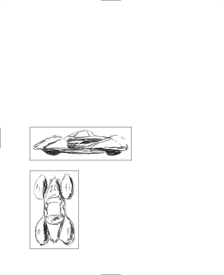
Figure 15.1 shows a sketch of the runabout from the right-hand side. Notice that it is really a sketch and not a drawing. As long as the general proportions and coarse features are present, it's satisfactory. Now if you were going to model a real car, you might need to use a more detailed sketch or perhaps something that would qualify more as a drawing than a sketch. Then again you may not—it all depends on how much detail is necessary to suit your needs.
The Side view is the main sketch we will use to make our model. When modeling most vehicles, you will usually use a Side view as your primary source for extrusion modeling. The reason for this is pretty obvious: Most
Figure 15.1 Side view sketch of the runabout. vehicles are longer than they are tall or wide. The symmetries of vehicles (how one side mirrors the other) tend to reflect
around the longitudinal axis, the one that runs from the rear to the front of the vehicle up the middle.
The Top view of the runabout is shown in Figure 15.2. The purpose for sketching this view is to provide a guide for your modeling efforts as they proceed. You will find yourself checking back against this drawing quite often.
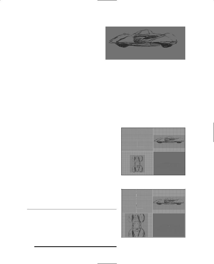
One more useful thing is to make a copy of the Side view and, using Paint Shop Pro, adjust the brightness of the image. This is because when we import the sketch into MilkShape, we don't want the image to overpower any of the on-screen modeling marks we make. I find the best approach is to darken the
whole image by around 40 to 50 percent and reduce the con-
Figure 15.2 Top view trast by about 50 to 60 percent or so. Figure 15.3 shows the sketch of the runabout.
Team LRN
|
The Vehicle Model |
467 |
adjusted Side view. I keep the original |
|
|
|
|
|
sketches as they were so that I can print |
|
|
them out for reference purposes (and also |
|
|
just to pin up on the wall because it's a cool |
|
|
artsy thing to do). |
|
|
The Model |
|
|
Figure 15.3 Side view sketch adjusted for use in |
|
|
So pour some gasoline in the ol' comput- |
MilkShape. |
|
er, grab the pull-start, and fire up |
|
|
MilkShape again if it isn't already running. If you need a quick refresher, you can jump back to Chapter 14. Set your MilkShape GUI display to the four-view mode by choosing Window, Viewports, 4 Window.
Create a fresh new MilkShape document. It's a good idea to save the empty file right now, just to get the path set up and establish the file name.
Then you want to import the side sketch as the background in the Side view (Top Right view). Right-click in the Side view and choose Choose Background Image from the pop-up menu. Select your sketch and click OK. You can use my sketch if you want—it's located at C:\3DGPAi1\RESOURCES\CH15\ref_sketch.bmp.
You should end up with something like Figure 15.4.
So now we start.
Building the Body
First, we'll build the body:
1.Select the Vertex tool, making sure that the Auto Tool check box is cleared.
2.In the Side view, start placing vertices at all the major corners and points around the edge of the car's body—don't do the fenders yet. See Figure 15.5 for reference.
n o t e
There is also a string of vertices across the "waist" of the body—in Figure 15.5 they are highlighted as black squares (they show red in MilkShape). These extra vertices are added for two reasons: First, they act as useful anchors for creating the faces that we'll make later. And second, they help add more malleability to the model for shaping the sides of the car.
Figure 15.4 MilkShape windows with reference sketch.
Figure 15.5 Placing vertices over the reference sketch.
Team LRN