

3D Game Programming All In One (2004)
.pdfThis page intentionally left blank
Team LRN
chapter 9
Skins
Skins are special textures used in games. The quality that separates skins from regular textures is that they typically wrap around the shape of a 3D model. It is fairly obvious that 3D monsters and player-characters would have texture skins, but the term can also apply to automobiles, wheelbarrows, mailboxes, rowboats, weapons, and
other objects that appear in a 3D game.
Typically, skins are created after a model has been unwrapped, so that the skin artist knows how to lay the skins out in the UV template. We're going to do the process a bit backward, simply because we should stay on topic with Paint Shop Pro and textures until we've covered the topic sufficiently.
In our case here, it isn't a big issue anyway, because I'm providing you with UV templates from previously UV unwrapped models to work with.
UV Unwrapping
UV unwrapping is a necessary function prior to skinning a model. Consider it part of the modeling process in the context of this book. However, in this chapter we'll deal with the texture processing part of skinning a model and use models I've provided on the CD. Later you'll create and skin your own models and do the unwrapping and other things. We'll cover how the unwrapping works in more detail then.
When we want to apply textures to 3D objects, we need a system that specifies where each part of a texture will appear on which parts of a model. The system is called U-V Coordinate Mapping. The U-coordinate and the V-coordinate are analogous to the X- and Y-coordinates of a 2D coordinate system, though they're obviously not exactly the same.
309
Team LRN
310Chapter 9 ■ Skins
Imagine (or you can actually try this at home yourself) taking a closed cardboard box and slicing it open along the edges. Then lay the whole thing out flat on the kitchen table, with no parts overlapping parts. There, you've unwrapped your box. Now get out your crayons and draw some nifty pictures on it. Then glue it all back together again to make a box. I think you get the idea.
With UV unwrapping we apply the technique to some complex and irregular shapes, like monsters and ice cream cones.
The Skin Creation Process
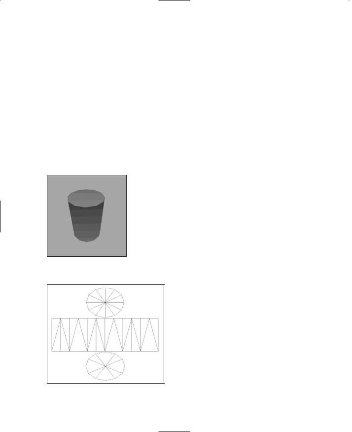
When we begin the skinning process, we will have a bare, unadorned 3D model of some kind. For this little demonstration, we'll use a simple soup can (see Figure 9.1). It's a 12-sided cylinder with a closed top and bottom (end caps). Each side face is made up of two triangles, and the end caps are made of 12 triangles each, for a total of 48 triangles. Nothing too special here.
Using the UV Unwrapping tool, we have to basically spread all our faces out over a nominally flat surface (see Figure 9.2).
We save the image of the UV template, plus we save the original model file, because the UV Unwrapping tool will have modified the UV coordinates for the objects in the model, and we can save those changes to the file so that the modeling tool can read them back in again.
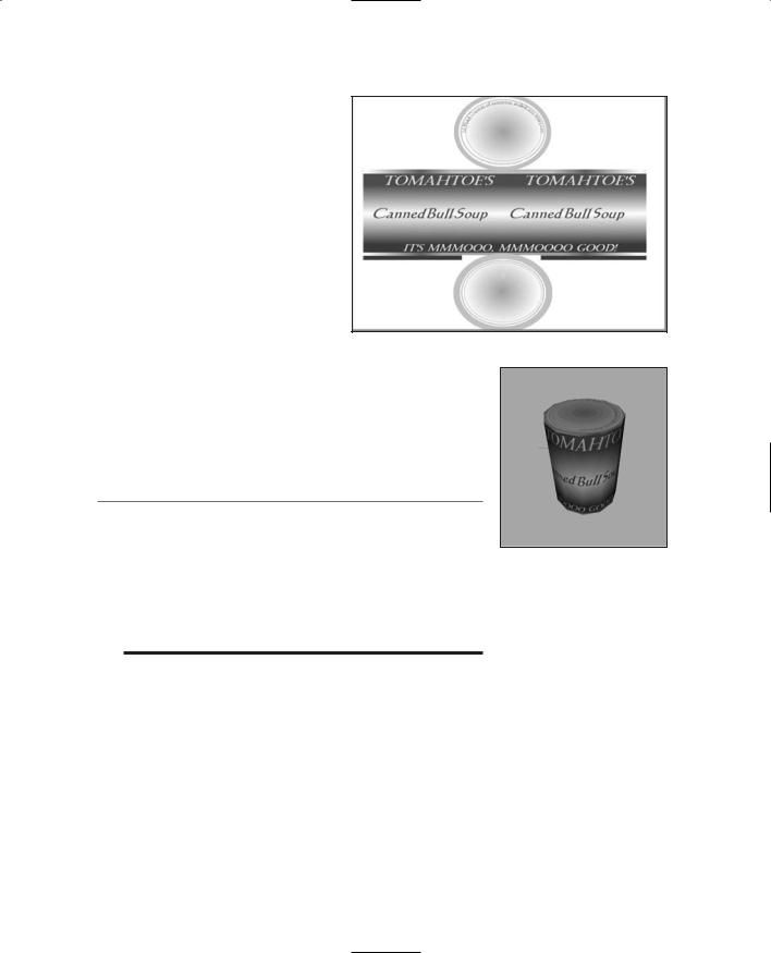
Then we import the unwrapped image with the lines indicating the face edges into an image processing tool like
Figure 9.1 The victim—a Paint Shop Pro and apply whatever textures, colors, or sym- simple can of soup.
bols we need, such as shown in Figure 9.3.
Notice that for textures I simply created markings and re-created a simple label. For the top of the can I made some circular text, and for both end caps I made a circular pattern that represents the ridges you often find in those places on tin cans. The image file has now officially become a skin for the can!
The final step is to import the new skin into the modeling program (or the game) and view the results, as in Figure 9.4.
The part of the process we will focus on in this
Figure 9.2 Laying it all out—the chapter is the activity shown in Figure 9.3, the unwrapped can.
actual creation of the textures on the UV
Team LRN
Making a Soup Can Skin |
311 |
template, so that it can be later used as a skin for models.
Making a Soup
Can Skin
So let's dive right in and create a skin. We can use the bare model of the soup can I showed you in the last section. The procedure has quite a few steps—more than 30—so we'd better roll up our sleeves and get to it.
Figure 9.3 After applying textures.
The Soup Can Skinning
Procedure
This is how you skin a soup can:
1.Open C:\3DGPAi1\resources\ch9\can.bmp in Paint Shop Pro. This file contains the UV mapping template.
t i p
Remember when I said that the only file types we would need to use are JPG and PNG in the last chapter? Well, that was sort of a lie, though not quite—you see, the only file types we will be using for making games will be those two types. However, the UVMapper program outputs its UV mapping templates as one of two types: BMP (Windows bitmap) or TGA (Targa) format. So I've picked BMP to be our standard UV mapping template format. We won't be creating any game files in this format, however.
Figure 9.4 Aha! Not such a simple can anymore. Nutritious, too!
2.Choose Image, Increase Color Depth, 16 Million Colors. You need to do this to get access to the full palette.
3.Save the file as C:\3DGPAi1\resources\ch9\mycan.psp. This way you can re-use the layers over and over at later times if necessary. Make sure you save your work often as you follow the steps, in case you royally mess up, like I frequently do.
4.Right-click the Layer palette (see Figure 9.5), and then choose New Raster Layer.
5.Accept the default settings and click OK.
6.Click Raster 1 to make that layer active.
7.Click the Preset Shape tool, third icon from the bottom of the Tools toolbar on the left.
Team LRN
312 Chapter 9 ■ Skins
Figure 9.5 Materials and Layer palettes.
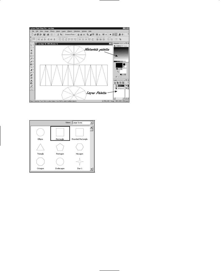
Figure 9.6 The Shapes List.
8.In the Tool Options palette (if it is not visible, choose View, Palettes, Tool Options to make it visible), click the Shapes List icon. The Shapes List will appear, as in Figure 9.6.
9.Choose the Rectangle from the Shapes List control; the list will go away automatically.
10.If the Create As Vector box on the Tool Options palette is checked, clear it.
11.If the Retain Style box on the Tool Options palette is checked, clear it.
12.In the Materials palette, locate the Foreground and Stroke Properties control. It is the upper-left box in the larger pair of boxes in the Materials palette.
13.Along the bottom of the Foreground and Stroke Properties are three buttons. Click the one on the far right with the No Entry icon, called Transparent. Now that it is depressed, the foreground or stroke of the object you draw will be transparent.
14.Click the Background and Fill Properties control, the lower-right control of the larger pair of boxes in the Materials palette. When the Color dialog box opens, select a bright red, and make sure it appears in the box marked Current. Then click OK to close the dialog box.
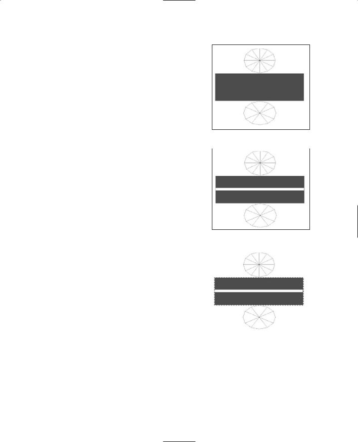
15.Now draw a rectangle that completely covers the rectangle containing the triangles in the middle of your mycan.psp image, as in Figure 9.7.
16.Now use the Background and Fill Properties control to set the fill to white, and draw a thin white rectangle across the middle of the red rectangle you just made (see Figure 9.8).
So now you have your basic red-and-white pattern on the sides of the can. If you look at Figure 9.3 again, you'll notice that the red blends into the white gradually. There are several ways to do this. For example, you could have used a gradient fill
Team LRN
Making a Soup Can Skin |
313 |
in the rectangles you created. But you're going to use another method, one that is more of a touchup technique.
17.First, you're going to select the sides of the can. Use the Square Selection tool (fifth icon down on the Tools toolbar) to select the entire rectangle that encloses all of the red and white rectangles you've just made, but only those areas. Use Figure 9.9 as a guide.
18. Next, soften the transition between the red and |
Figure 9.7 The red rectangle. |
|
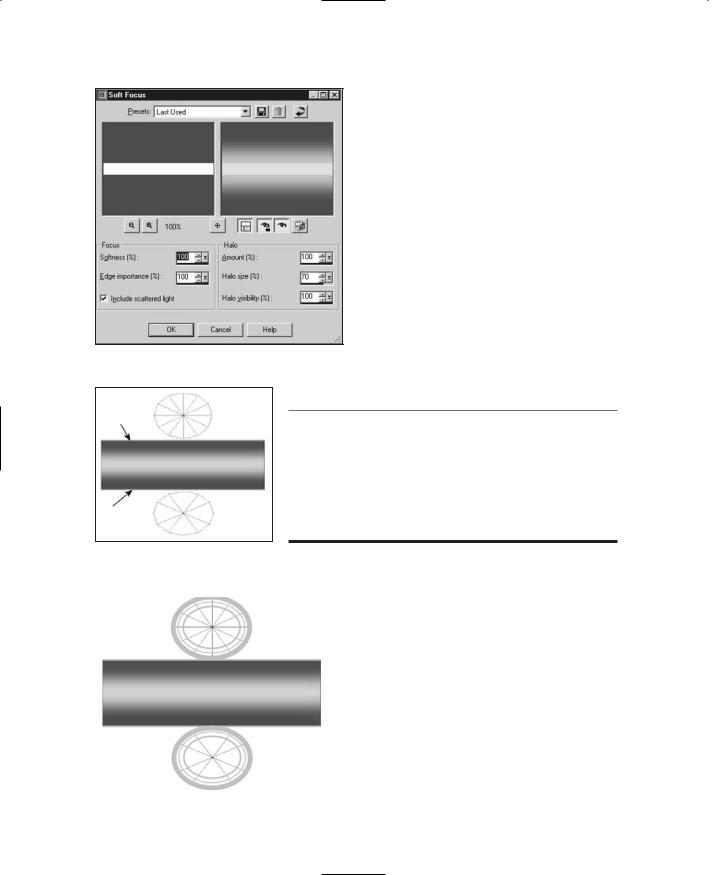
the white. Choose Adjust, Softness, Soft Focus. |
||
|
||
You will get the Soft Focus dialog box, as |
|
|
|
||
shown in Figure 9.10. |
|
19.Set all of the values in the boxes to 100 percent, except for Halo size. Set Halo size to 70 percent, and then click OK to close the box. You'll see the edges between the red and the white go blurry.
20.Repeat the last two steps—choose Adjust, Softness, Soft Focus, and then make sure all values
are set to 100 percent (except Halo Size, which |
Figure 9.8 |
The white rectangle. |
|
is set to 70 percent) and close the dialog box. |
|
|
|
There now—you have your blended pattern. |
|
|
|
21. Next you'll want to add metal lips to the top |
|
|
|
and bottom of the can sides. Do this by creat- |
|
|
|
ing a thin light gray rectangle all the way across |
|
|
|
the top and another at the bottom, as shown in |
|
|
|
Figure 9.11. The black arrows indicate the loca- |
|
|
|
tion of the lip line. |
|
|
|
22. Now you'll want to create the surface texture |
|
|
|
for the ends, or lids, of the can. Once again, |
|
|
|
Figure 9.9 |
Selecting the mapped |
||
select the Preset Shape tool. |
sides of the can.
23.In the Tool Options palette, click on the Shapes List icon.
24.Choose the Ellipse from the Shapes List control.
25.This time make sure that the Create as vector box is checked.
Team LRN
314 Chapter 9 ■ Skins
Figure 9.10 Soft Focus dialog box.
t i p
26.Set the foreground color to a light gray and the background color to transparent, using the same technique you used when drawing the rectangles earlier.
27.Draw a series of concentric ellipses in both the top and bottom list shapes (see Figure 9.12). Make sure to leave a sizable gap between the inner ellipse and the one next to it.
Also use a line width of about 15 for the outermost ellipse, 2 for the middle ellipse, and 4 for the innermost one. The ellipses are drawn from the center out. You may need to fiddle a bit before you get it right.
You can adjust the size of your vector object ellipses by grabbing the little black handles on the shapes while the object is selected. If it isn't selected, use the Object Selection tool (the bottom tool of the Tools toolbar) to select your ellipse by clicking on it.
You can also drag your ellipses around this way. Press Ctrl+Left Arrow to nudge the object a bit to the left. Press the Ctrl key with the other arrow keys to nudge the object in other directions.
Figure 9.11 |
Adding the metal |
|
||
lips. |
28. |
Next, select the Text tool, which is fourth |
||
|
||||
|
|
|
from the bottom of the Tools toolbar. If |
|
|
|
|
||
|
|
|
you have any objects already selected, des- |
|
|
|
|
elect them by clicking the Object Selec- |
|
|
|
|
tion tool on an empty part of the image |
|
|
|
|
before selecting the Text tool. |
|
|
|
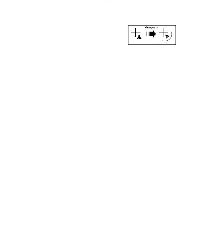
29. |
As you move the Text tool cursor around, |
|
|
|
|
it will have an icon like the one on the left |
|
|
|
|
in Figure 9.13. When you move it over a |
|
|
|
|
vector object, the cursor will change to |
|
|
|
|
the one on the right in Figure 9.13. |
|
|
|
|
Move the cursor over the top part of the |
|
|
|
|
innermost ellipse object in the upper set |
|
Figure 9.12 |
Adding the ridges. |
|||
of concentric rings. |
||||
Team LRN
30.Now click on that object; you will get the Text Entry dialog box. Select the font you want from the Tool Options palette.
31.Use a font size of 12 and make sure you set the stroke width to 1.0.
Making a Soup Can Skin |
315 |
Figure 9.13 Text tool cursors.
32.Type in your text, something like 16 Fluid Ounces.
33.Make sure you have vector set in the Create As control; then click Apply.
34.Voilá! You will have text that follows the curve of the ellipse around in an arc.
35.Now add your main label text using the Text tool. You can type whatever you want and position it wherever you want.
36.When you are finished, save your file one final time as C:\3DGPAi1\resources\ch9\mycan.psp. This is your source file.
37.Next, save your work as C:\3DGPAi1\resources\ch9\mycan.jpg. Make sure you've selected the "JPEG – JIFF Compliant" type in the Save As dialog box when you do this.
38.You will get an alert saying that it will have to save the file as a merged image and asking if you want to continue. This is expected because the JPG format doesn't support layers. Click Yes.
Testing the Soup Can Skin
Congratulations! You've made your first skin! I suppose now you want to see what it looks like all wrapped around a tin can and everything. Okay, so do this:
1.Browse your way to C:\3DGPAi1 and then double-click on the Show Book Models shortcut.
2.The Torque Engine will fire up with a special program called the Show Tool. Click on Load Model.
3.Find mycan.dts and load it.
4.Presto! That's your skin on that there soup can! Good job!
5.You can admire your creation in all its splendor by using the navigation keys to move the can back and forth and rotate it about the various axes. See Table 9.1 for the Show Tool key commands.
6.You can view my original soup can skin by loading the soupcan.dts model.
Team LRN

316 Chapter 9 ■ Skins
Table 9.1 Torque Show Tool Navigation Commands
Key |
Description |
A |
rotate left |
D |
rotate right |
W |
bring closer |
S |
move farther away |
E |
rotate top backward |
C |
rotate top forward |
Making a Vehicle Skin
Okay, soup cans are cool and soup hits the spot, too. But now that lunch break is over, let's move on to something a bit more serious. Many people are going to have vehicles in their games, and the Torque Engine does quite a nice job of supporting vehicles. We'll be making our own vehicles later, but because this chapter is on creating skins, let's make a skin for some kind of vehicle.
For a bit of a tease, let's take a look at a vehicle that is already included in the Torque demo using the Show Tool.
1.Browse to C:\3DGPAi1 and click on the Show Racing Models shortcut. This is not the same shortcut as Show Book Models.
2.Click Load Shape.
3.From the list, select buggy.dts, which is near the bottom.
4.Zoom in using the navigation keys and take a gander at the buggy chassis. Pretty cool, huh? Notice that it has no wheels. In Torque we model the wheels separately, so that we can model the suspension action of the vehicle more accurately.
The Dune Buggy Diversion
Okay, okay. I knew you would want to do this, so I'll show you how to test-drive the dune buggy in-game, as long as you promise to come back here after you've tired out your driving fingers. People tend not to learn quite as well when they are pouting.
1.Browse to C:\3DGPAi1 and click on the Run racing Demo shortcut.
2.Click on Start Mission.
3.In the Launch dialog box, make sure that the Multiplayer Mission box is cleared.
4.Select Car Race Track from the mission list.
5.Click Launch.
Team LRN

Making a Vehicle Skin |
317 |
6.After the game loads, have at it! You probably should switch to Chase view by pressing the Tab key—there's more to see. See Table 9.2 for the keyboard controls.
Table 9.2 Torque Racing Demo Controls
Key |
Description |
mouse |
steering left or right |
W |
accelerate |
S |
brake |
Tab |
toggle from firstto third-person viewpoint |
Escape |
exit the game |
The Runabout Skinning Procedure
Okay, now that the old adrenaline is pumping, let's get back to making skins. We're going to create a skin for a less ambitious, but still pretty cool, vehicle—the runabout. It's a fictional creation of mine that's a convergence of memories of summers spent reading Doc Savage pulp stories and memories of a classic 1936 Auburn Boattail Speedster that I saw at a car show once as a teenager.
1.Open C:\3DGPAi1\resources\ch9\runabout.bmp in Paint Shop Pro. This file contains the UV mapping template.
This time, I've unwrapped the object differently. If you recall, the soup can was completely unwrapped so that each individual face was lying flat. This time I unwrapped the runabout by showing only the separate objects (except the cab) from one particular view—the side or the top.
By doing this, I can treat each of these objects as symmetrical, with the hidden side being simply a mirror image of the visible side. This is another valid technique, but it does have some pitfalls, which we will encounter. The advantage of using this approach is that it saves on image editing time, because only half of the objects' surfaces need to be given textures.
2.Select the Pen tool (second from the bottom). Set the line color to red and the fill to transparent.
3.Select Segment Type to be Point to Point on the Tool Options palette, as shown in Figure 9.14.
Figure 9.14 Point to Point Segment Type button.
Team LRN