

The Microcontroller Idea book (Jan Akelson, 1997)
.pdfChapter 3
Table 3-2. Voltage specifications for different types of logic, powered at 5V.
Logic Type |
Output |
|
Input |
|
|
|
|
|
|
|
0 (maximum) |
1 (minimum) |
0 (maximum) |
1 (minimum) |
|
|
|
|
|
TTL, including LSTTL |
0.4V |
2.4V |
0.8V |
2.0V |
most NMOS |
|
|
|
|
HCTMOS |
0.1V |
4.9V |
0.8V |
2.0V |
HCMOS |
0.1V |
4.9V |
1.0V |
3.5V |
4000-series CMOS |
0.1V |
4.9V |
1.5V |
3.5V |
|
|
|
|
|
Table 3-2 summarizes the input and output voltage specifications for different logic-device families. The main point to remember is that a TTL logic-high output voltage (and most NMOS high outputs) may be as low as 2.4V, which does not meet the minimum input-voltage requirement for HCMOS or 4000-series CMOS devices. To interface a TTL output to CMOS, use an HCTMOS device, which accepts TTL-logic inputs. Or, you may add a pull-up resistor to a TTL output to pull it near +5V.
Serial Interface
The final chip in the schematic is U5, a MAX232 driver/receiver, which is the popular single-chip solution for RS-232 interfaces. One side connects to the 8052’s serial input and output on pins 10 and 11 of U1, and the other side sends and receives signals at standard RS-232 levels to a personal computer. Larger capacitor values for C4-C7 are fine, and the MAX232A version can use values as small as 0.1 microfarad. If you splurge on a MAX233, which has internal capacitors, you don’t need C4-C7 at all.
Power Supply
A final essential component is the power supply. For the basic system, all you need is a regulated +5-volt supply. These are widely available from mail-order suppliers. An output capability of at least 500 milliamperes is recommended.
Capacitors C8-C13 provide power-supply decoupling. Digital devices draw current as they switch. Capacitors C9-C13 store energy that the components can draw quickly, without causing spikes in the supply or ground lines. C8 stores energy for quick recharging of C9-C13. The exact values aren’t critical, but C9-C13 should be a type with good high-fre- quency response, such as ceramic, mica, or polystyrene.
LED1 and current-limiting resistor R10 are an optional power-on indicator.
30 |
The Microcontroller Idea Book |

Powering Up
Figure 3-3. This is the circuit board on which I wire-wrapped and tested many of the circuits in this book.
Circuit Construction
This circuit is intended for use as a flexible system for testing and experimenting, rather than a fixed, unchanging design for a single application. For this reason, I recommend building it with wire-wrapping or another construction method that allows easy changes and additions. Figure 3-3 shows an 8052-BASIC circuit wire-wrapped onto perfboard.
Reading the Schematic
In the schematic, I used a couple of different techniques to represent connections between pins and components. In the reset circuit, connections are drawn as direct point-to-point lines. For the address and data lines, I used buses for a neater, more compact schematic. When you wire these connections, use the signal labels as a guide. For example, the label D0 tells you to interconnect these points: pin 39 of U2, pin 3 of U4, pin 11 of U7, and one end of R2. Other connections are indicated by labels. For example, the WRITE label tells you to connect pin 16 of U2 and pin 27 of U7.
Another point to be aware of is the conventions used in the schematics and text of this book for indicating an active-low signal, or a signal that is valid, or enabled, when low. In this book, the schematics use a leading hyphen (-WRITE) , while the text uses an overscore (WRITE). Their meanings are the same.
The Microcontroller Idea Book |
31 |
Chapter 3
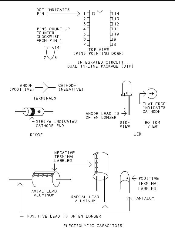
Figure 3-4. How to determine the correct orientation for ICs, diodes, LEDs, and electrolytic capacitors.
32 |
The Microcontroller Idea Book |

Powering Up
Construction Tips
These are some things to be aware of as you build the circuit:
•Choose a circuit board that has room for additions, at least 4 by 6 inches.
•A board with interleaved buses, such as Vector’s 3677 series, allows easy, low-impedance connections to +5V and ground. Designate one bus as ground, and the other as +5V. For power and ground connections, wrap one end of the wire to the appropriate pin on the chip, and trim and solder the other end directly to the bus.
•To connect the power and ground buses to the +5V supply, use thick (AWG #22 or lower) wires, not #30 wire-wrap wires. You can solder the other ends of the wires to banana plugs or screw terminals, or clip your power-supply leads directly to the wires.
•The schematic doesn’t show an ON/OFF switch for the circuit, but you can add a SPST toggle or slide switch in series with the connection to the +5V supply if you wish.
•Place C8 near where the +5V supply connects to the board. Mount decoupling capacitors C9-C13 so that each chip’s +5V and GND pins are near a capacitor. In other words, space the capacitors evenly around the board; don’t group them all in one area. Keep the wires or traces between the capacitor’s leads and the IC’s +5V and ground pins as short as possible.
•To minimize noise in the oscillator circuits, place XTAL1, C2, and C3 close to pins 18 and 19 of U2 and connect them with short wires. Wire the ground terminals of C2 and C3 directly to pin 20 of U2.
•When you wire the following components, correct orientation is required: C1, C4-C8, D1, LED1, and U1-U7. Figure 3-4 shows common polarity indicators for these components. Notice that C7’s positive terminal connects to ground, and C6’s negative terminal connects to +5V, since these capacitors connect to the MAX232’s -10V and +10V outputs.
•As you wire the circuits, remember that everything on the wire-wrap or solder side of the board is a mirror image of the way it looks on the component side of the board. If pin 1 is in the upper left corner on the component side, it’s in the upper right corner on the wire-wrap side (assuming that you flip the board over from side to side, not top to bottom).
•Labels on the wire-wrap side are helpful. You can place a dot of indelible ink near pin 1, or adhesive labels between the pins, or use prelabeled and punched plastic labels that slide onto the wire-wrap pins.
The Microcontroller Idea Book |
33 |

Chapter 3
Figure 3-5. Pin connections for 25-pin and 9-pin RS-232 connectors.
• Don’t plug the ICs into their sockets until you’ve completed wiring all of the circuits.
Unused Gates
Two gates on U3 and five gates on U1 are unused. To prevent the unused CMOS inputs from floating and possibly drawing excessive currents, wire pins 9, 10, 12, and 13 of U3 to ground or +5V. Do the same for pins 3, 5, 9, 11, and 13 of U1. Don’t forget to remove these connections if you later use the pins. If you are using LSTTL chips (74LS08, 74LS14), leave the unused inputs open.
34 |
The Microcontroller Idea Book |

Powering Up
Serial Connectors
Connections to RS-232 OUT and RS-232 IN depend on the type of serial connector you have on your personal computer or its serial cable.
Connectors vary, but two common ones are a male 25-pin or 9-pin D-connector. (The outer shell of a D-connector is roughly in the shape of a D.) For the 8052-BASIC system, you’ll need a mating female 25-pin or 9-pin D-connector. The connection has just three wires. A solder-cup-type connector allows easy soldering of the wires.
Figure 3-5 shows the wiring for 9- and 25-pin connectors. A few computers require additional handshaking signals. BASIC-52 doesn’t support these, but you can simulate them by connecting together pins 5, 6, 8, and 20 at the personal-computer end of the link. (Pin numbers are for a 25-pin connector.)
Powering Up
The first time you power up an untested circuit, it pays to be cautious. I recommend the following steps:
First Steps
Visually inspect the circuit. You don’t have to spend a lot of time on this, but sometimes a missing or miswired wire or component or another problem will become obvious.
Install U1-U7 on the board, making sure that pin 1 on each is oriented correctly. Set J1 to BASIC, and set J2 and J3 to match the size of your RAM at U7.
With an ohmmeter, measure the resistance from +5V to ground, to be sure these aren’t shorted together by mistake. The exact value you measure isn’t critical, but if you read less than 100 ohms, something is miswired and you need to find and fix the problem before you continue.
If you suspect a problem, check the wiring of the power and ground connections, comparing the connections to those on the schematic. Be sure all components are oriented correctly. When all checks out, you’re ready to boot up BASIC-52.
Booting BASIC-52
For the initial check, begin with everything powered down. I’ll use the term host computer, or host system, to refer to the personal computer, and target computer, or target system, to refer to the 8052-BASIC circuits. Included are some specific tips for users of Datastorm’s
The Microcontroller Idea Book |
35 |

Chapter 3
Figure 3-6. BASIC-52’s sign-on message and a simple program, using the Windows Terminal accessory for communications.
Procomm Plus for DOS and Microsoft Windows 3.1’s Terminal Accessory, but other communications software should have similar features and abilities.
Turn on the host computer and run your communications software. Configure the software for 8 data bits, no parity, and 1 stop bit. The baud rate you select isn’t critical, since BASIC-52 automatically adjusts to what you are using. To start, use a rate of 9600 or less. Don’t enable any handshaking or flow-control options such as XON/XOFF or RTS/CTS.
Select the appropriate serial, or COM, port, if necessary. If you’re using an MS-DOS (IBM-compatible) computer, you must find a COM port and interrupt-request (IRQ) level that aren’t being used by your modem, mouse, or another device. Because COM1 and COM3 often share an IRQ level, as do COM2 and COM4, you generally can’t use COM1 and COM3 at the same time, or COM2 and COM4. If you have an external modem, you can unplug it and use its serial port.
In Procomm Plus, use the line/port setup menu (ALT+P) to configure. In the Windows Terminal, use the Settings menu. Cable together the serial ports of the host and target systems.
36 |
The Microcontroller Idea Book |

Powering Up
You’re now ready to power up the target system. Turn on its power supply, and press the SPACE bar at the host’s keyboard. You should see this BASIC-52 sign-on message and prompt:
*MCS-51(tm) BASIC V1.1*
READY
Figure 3-6 shows the sign-on message and a simple program, using Windows’ Terminal accessory for communications.
Troubleshooting
If you don’t see the prompt, it’s time to troubleshoot. Getting the system to boot up the first time can be the most challenging part of a project, especially when serial communications are involved. Here are some things that may help you isolate the cause of the problem:
•Try again by pressing and releasing S1 and pressing the space bar. If you are using a 32K RAM for U7, BASIC-52 requires about 1 second to perform its memory check after a reset, before it will respond to the space bar. With an 8K RAM, the delay is a few tenths of a second (proportionately longer with slower crystals).
•Double-check the easy things. Are the communications parameters correct? Did you select the correct serial port? Are all ICs inserted?
•Verify that pin 9 of U2 goes high, then low, when you press and release S1.
•Check the power and ground pins of all ICs for proper voltages.
•Connect a logic probe to pin 10 of U2. When you press the space bar, you should see the logic level toggle as U2 receives the ASCII code for a space (20h). If not, you probably have a problem in the setup of your communications software or in the serial cabling.
•Verify that pin 30 of U2 is toggling (at 1/6 the crystal frequency, if you have an oscilloscope to measure). This indicates that the oscillator circuit is functioning.
•Verify that pins 21-28 and 32-39 of U2 toggle as BASIC-52 performs its memory check immediately after powering up or rebooting.
•If all else fails, recheck your wiring for missing or misrouted wires. Sometimes there’s no alternative but to go through the schematic connection by connection, checking each with an ohmmeter.
The Microcontroller Idea Book |
37 |

Chapter 3
Basic tests
When your system boots, you’re ready for some basic tests. The BASIC-52 programming manual is a useful reference at this point.
In some ways, BASIC-52 is similar to BASIC compilers like Microsoft’s QuickBASIC. Many of the keywords and syntax rules are similar. But BASIC-52 is closer to older interpreted BASICs like GW-BASIC or BASICA. You can type a statement or command and execute it immediately when you press ENTER, or you can type a series of statements and run them later as a program. When a line begins with a line number, BASIC-52 treats it as a program line rather than as a command to execute immediately.
Here are some quick tests and experiments you can do:
Memory Check
Type
PRINT MTOP
to learn the amount of external data memory that BASIC-52 detected on boot-up. With an 8K RAM, MTOP should be 8191, and with 32K, it should be 32,767. If you prefer hexadecimal notation, type
PH0. MTOP
(In PH0., be sure to include the period and use a zero, not the letter “O”.)
Crystal Frequency
The special operator XTAL represents the value of the timing crystal that clocks the 8052-BASIC. The default value is 11059200, or 11.0592 Mhz. You can verify this by typing
PRINT XTAL
Most BASIC-52 statements don’t use the XTAL operator, so it doesn’t matter if the value isn’t accurate. Exceptions are the real-time clock, programming commands, PWM output, and LPT output. For these, XTAL should match your crystal’s frequency. To set XTAL for a 12Mhz crystal, type
XTAL=12000000
To verify, type
38 |
The Microcontroller Idea Book |

Powering Up
PRINT XTAL
Line Editing
After typing a few commands, you may discover some of BASIC-52’s line-editing abilities. While typing a line, you can correct mistakes by deleting back to the mistake and retyping. In Procomm Plus, if you select VT100 terminal emulation (under Setup menu, Terminal Options), you can use either the DELETE or BACKSPACE key to delete. With the Windows terminal, you must use the DELETE key (not BACKSPACE). Many communications programs allow you remap the keyboard, so you can select whatever delete key you wish.
Once you press ENTER, you can’t edit a line you’ve typed, unless you retype it from the beginning.
BASIC-52 treats upper and lower-case characters the same. In most cases, spaces are ignored, so you can include them or not as you wish.
Running a Program
Here is a very simple program to try:
10 FOR I=1 to 10
20 PRINT I
30 NEXT I
40 END
Enter each of the lines, including the line numbers. BASIC-52 automatically stores the program in RAM. To run the program, type RUN. You should see this:
1
2
3
4
5
6
7
8
9
10
To view the program lines, type
LIST
The Microcontroller Idea Book |
39 |