

The Microcontroller Idea book (Jan Akelson, 1997)
.pdfWireless Links
Figure 12-6. Using an 8255 to control an infrared transmitter.
The encoder’s transmit enable (TE) input connects to Port C, bit 7 on the 8255, which you can set and clear with the 8255’s bit-control instructions.
Listing 12-1 shows a BASIC-52 program that causes the Figure 12-6’s encoder to send a 4-bit value to Figure 12-2’s decoder. The program asks for an address and data to transmit, writes the information to Port A, and then brings bit 7 of Port C low, then high, to cause the encoder to transmit the information. If the transmitted address matches the decoder’s, the transmitted data appears at the decoder’s data outputs, and its VT (valid transmission) output goes high. If the addresses do not match, or if the decoder detects an error in transmission, VT remains low and the decoder ignores the data.
If you want to do everything with a single 8-bit port, you can tie another of the encoder’s address inputs high (or low, or leave it open), and use the additional bit on Port A to control TE. If you do this, you’ll have to use Boolean operators (AND, OR) to ensure that the data and address don’t change when you toggle TE. If you know you are going to transmit to only one address, you can hard-wire all of the encoder’s address inputs and free up four bits on the 8255 for other uses.
The Microcontroller Idea Book |
209 |

Chapter 12
Listing 12-1. Causes an encoder to transmit requested data.
10 |
REM 8255 mode set: Ports A,C = output, Port B = input |
20 |
XBY(0FC03H)=82H |
30 |
DO |
40 |
INPUT “Enter the decoder’s address (0-15): ”,A |
50 |
INPUT “Enter the data to send (0-15): ”,D |
60 |
REM Write the address and data information to Port A |
70 |
XBY(0FC00H)=(D*10H+A) |
80 |
REM Toggle TE (Port C, bit 7) |
90 |
XBY(0FC03H)=0EH |
100 |
XBY(0FC03H)=0FH |
110 |
WHILE 1=1 |
120 |
END |
Computer-controlled Receiver
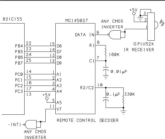
Instead of, or in addition to, computer control of the transmitter, you can also add a computer interface at the receiver. For example, a data logger might accept data from a remote transmitter and process the data or store it for later use. Figure 12-7 shows a receiver similar to Figure 12-2’s, with the manual controls replaced by port bits of an 82(C)55.
The circuit uses different port bits from Figure 12-6’s circuit, so you can connect both a transmitter and a receiver to one 8255 if you wish. The low nibble of Port C is configured as an output, and sets A1-A4 on the decoder. As in the previous circuit, A5 is tied high so you can set the address with 4 bits. Port B is configured as an input, and its bits 4-7 store the data received at the decoder’s D6-D9. VT is inverted and then connects to the 8052’s INT1 (pin 13). You can use any CMOS inverter.
Listing 12-2 is a BASIC-52 program that sets up the 8255 to receive data at port B, in Mode 0. The program writes an address to the decoder’s address inputs, and also turns off TE (PC.7 in Figure 12-6, to ensure that the encoder on this end (if connected) isn’t transmitting while the decoder is receiving. The program uses an edge-detecting interrupt to ensure that the program won’t re-interrupt if VT is still low when the interrupt routine ends.
The main program is a do-nothing loop that waits for an interrupt. When VT goes high, indicating that a valid transmission has been received, the 8052-BASIC executes an interrupt routine that reads the data at bits 4-7 of Port B and displays it on the host computer.
Using VT to generate an interrupt is a handy way to detect when new data has arrived, but you don’t have to use interrupts. If you don’t enable interrupt 1, you can read Port 3’s bit 3 periodically to find out if a new transmission has arrived. Or, you can leave VT unconnected
210 |
The Microcontroller Idea Book |
Wireless Links
Figure 12-7. Using an 8255 to control and access an infrared receiver.
and just read Port B once a minute, or on user request, or trigger the reading by some other factor under program control.
As with the encoder circuit, you don’t have to use an 8255 to read and write to the decoder. Any latched port outputs will do for A1-A4, and any port inputs will do for D6-D9. Because the decoder latches the data, you don’t need additional input latches. If the circuit will receive data from only one address, you can hardwire the decoder’s A1-A5 and free up four bits on the 8255 for other uses.
You can transmit to Figure 12-7’s circuit with either a manual or computer-controlled transmitter. Set the transmitter’s address inputs to match the receiver’s address, select the data you want to send, transmit, and view the received data on the 8052-BASIC system’s host display.
The Microcontroller Idea Book |
211 |

Chapter 12
Listing 12-2. |
Reads received data at the decoder. |
|
10 |
REM 8255 mode set: Ports A,C = output; Port B = input |
|
20 |
XBY(0FC03H)=82H |
|
30 |
REM |
A=decoder address (0-15) |
40 |
A=2 |
|
50 |
REM Write address to Port C, turn TE (PC.7) off (high) |
|
60 |
XBY(0FC02H)=80H+A.OR.XBY(0FC02H) |
|
70 |
REM Use edge-triggered interrupt |
|
80 |
TCON=TCON.OR.4 |
|
90 |
DO |
|
100 |
REM Wait for interrupt |
|
110 |
ONEX1 500 |
|
120 |
WHILE 1=1 |
|
130 |
END |
|
480 |
REM On interrupt 1, print received data |
|
490 |
REM Data is at Port B, bits 4-7 |
|
500 |
PH0.(XBY(0FC01H).AND.0F0H)/10H |
|
510 |
RETI |
|
|
|
|
You can have more than one receiver in a link. If each has a unique address, it will accept only the transmissions meant for it.
Increasing the Distance
When you have your link up and running, one of the first challenges is to see how far you can reliably transmit. Two ways to increase the length of the link are by increasing the power of the transmitted signal, and by focusing the signal more precisely on the receiver.
About Infrared Energy
But first, some basics about infrared. Like visible light, infrared energy is a form of electromagnetic radiation. Infra means below, and infrared frequencies are just below those of red light. Infrared frequencies are invisible, or beyond the range detected by the human eye. Since wavelength is the inverse of frequency, infrared wavelengths are longer than those of visible light. Visible light covers the range 400-700 nm (nanometers), while infrared includes 700 nm through 1 million nm. (400 nanometers is 0.4 micron, or 4000 angstroms.)
Infrared-emitting diodes, or IREDs, are low-cost, widely available sources of infrared energy. An IRED is a semiconductor diode that emits infrared energy when a forward current passes through it, much as an LED emits visible light.
212 |
The Microcontroller Idea Book |
Wireless Links
IREDs emit energy at specific wavelengths. Two popular types are GaAs (gallium arsenide), at 940 nm, and GaAlAs (gallium aluminum arsenide), at 880 nm. These are both in the range known as near infrared, to signify that their wavelengths are close to the visible spectrum.
Infrared detectors are also specific in the wavelengths they detect, although most will respond over a range. For example, the Sharp GP1U52X receiver module is most sensitive at 980 nm, but will also respond to the longer-wavelength emissions from GaAs and GaAlAs IREDs. Although the GaAs IREDs are a closer match at 940 nm, the GaAlAs IREDs tend
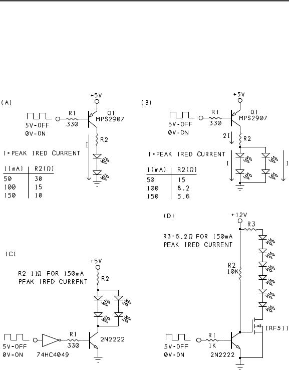
Figure 12-8. Circuits to increase the power and transmitting distance of an infrared link: (A) IREDs in series, (B) IREDs in parallel with PNP transistor driver, (C) IREDs in parallel with NPN transistor driver, and (D) MOSFET driver.
The Microcontroller Idea Book |
213 |

Chapter 12
to be more efficient, so they may work as well even though 880 nm isn’t as good a match with the detector.
Alternate Drive Circuits for IREDs
You can increase the strength of an infrared signal in two ways: by increasing the current through the IREDs, or by increasing the number of IREDs. Figure 12-8 shows both options, in a variety of circuits. All connect to the output of the NAND gate that combines the encoder’s output and the 40-kilohertz oscillator in Figures 12-1 and 12-5.
Series drive. A simple way to double the power is to use two IREDs in series, as Figure 12-8A shows. With about 1.7 volts across each IRED, the series combination drops 3.4 volts. Instead of wasting energy by dropping 3 volts across a resistor, more of the current does useful work by powering a second IRED.
The maximum possible current through the IREDs is determined by the transistor’s base current and gain. Outputs in the 74HC logic family can sink up to 25 milliamperes (absolute maximum), and are a good choice for driving the base.
Resistor R2 controls the amount of current through the IREDs. To determine a safe current through an IRED, you need to know the specifications of the IRED you are using, as well as how you plan to use the IRED in your circuit. The data sheet for any IRED should include an absolute maximum rating for continuous current. This is the maximum current that the device can withstand without damage. For example, for Harris’ F5D1, this value is 100 milliamperes. When the IRED is powered continuously, the current through it shouldn’t exceed this value. Since this is an absolute maximum, it’s a good idea to stay well below it.
The infrared transmitter doesn’t require the IRED to be on continuously, however. Instead, it pulses the IRED at 40 kilohertz. In non-continuous, or pulsed, operation, the IRED can handle much greater currents. The amount of allowable current depends on the pulse’s duty cycle, which equals the width of a pulse divided by the width of a complete on-and-off cycle.
Unfortunately, the data sheets often do not say how to determine the limits for a particular pulse width and repetition rate. Occasionally, you get a graph of maximum forward current versus pulse width and duty cycle. Other data sheets just offer a few examples.
The F5D1’s data sheet includes just two ratings for pulsed operation. For 10-microsecond pulses repeating at 100 Hz, the IRED’s maximum peak current is 3 amperes, or 30 times the continuous rating. And for even shorter 1-microsecond pulses, repeating at 200 Hz, the maximum is 10 amperes. But neither of these describes the situation for the infrared transmitter.
214 |
The Microcontroller Idea Book |

Wireless Links
In the infrared link, the amount of time the IRED is on depends on what information it is sending, and how often it transmits. When the IRED is pulsed at 40 kilohertz, it is on for just half of each 25-microsecond cycle. But the IRED pulses only when transmitting logic high outputs from the encoder. For logic low outputs, and when no data is transmitting, the IRED is off.
With the encoder chip clocked at 1 kilohertz, an encoded “1" contains two 3.5-millisecond high pulses and two 0.5-millisecond low pulses. This means that the IRED is pulsing almost 90 percent of the total time. If the 40-kilohertz oscillator has a 50-percent duty cycle, the IRED is on for half of this time, or 45 percent of each transmission. If you send a lot of 0’s (if the receiver’s address is 00, for example), or if you send only occasional, short transmissions, the average current will be much less.
In Figure 12-8A, with R2 at 30 ohms, the peak current through the IREDs is about 50 milliamperes, and the average current is under 25 milliamperes, well below the 100-mil- liampere limit. Even at a peak current of 150 milliamperes, the average over each transmission cycle will be under 70 milliamperes, still a safe level.
If you do pulse the IRED at 100 milliamperes or more, you have to be very careful to design your circuit so that the IRED never comes on continuously. When not transmitting data, the IRED should be off. At higher currents, it’s a good idea to use a current-limiting resistor with a 1/2-watt or greater power rating.
Parallel drive. If two IREDs aren’t enough, you can add two more in parallel, as Figure 12-8B shows. The value of the current-limiting resistor is smaller because it has twice the current through it, but the same voltage drop across it. Figure 12-8C shows four IREDs powered by an NPN transistor. A 74HC4049 inverter controls the transistor’s base current. With multiples of this circuit, you can have as many IREDs as your power supply can support.
12V drive. And finally, if you have a 12-volt supply available, you can add up to six IREDs in series, as Figure 12-8D shows. The IRF511 MOSFET turns on when a voltage is applied to its gate. To turn on fully, the MOSFET requires a gate voltage greater than 5 volts.
For more powerful transmissions to a specific receiver, you can mount multiple IREDs in a cluster, all pointing at the receiver. If you want to transmit to multiple receivers, or if a receiver’s exact location is unknown, you can mount the IREDs so that they transmit across a wider path.
Using Lenses
Another way to increase the range of a link is with optical lenses that focus or spread the transmitted energy.
The Microcontroller Idea Book |
215 |

Chapter 12
Some IREDs are manufactured with integral lenses that focus the output into a beam. For example, Harris’ F5D1 and F5E1 IREDs are identical, except that the F5D1 has a lens that aims the energy in a narrow beam, while the F5E1 has a flat window and wider beam angle. An IRED with an integral lens is an easy, low-cost option, if it can do the job. A flat-window package is useful if you want to add an external lens, or if you want a wider beam, to reach multiple receivers around a room, for example.
If you’re interested in experimenting with lenses, Edmund Scientific has a huge selection, including inexpensive educational-grade lenses, lens mounts, optical benches, and books on optics.
Although infrared links are most often thought of as line-of-sight paths—for transmitting across a room, for example—optics can also overcome this limitation. For example, with mirrors, you can transmit around corners.
Radio Links
Another possibility for wireless links is to use radio frequencies. Radio transmissions consist of high-frequency electromagnetic waves that travel through the atmosphere. Most radio waves will also pass through windows, walls, and other solid objects. This makes radio useful where a direct line-of-sight between transmitter and receiver isn’t available. Radio can also be a good choice for outdoor links, where daylight may interfere with infrared transmissions and wired links are inconvenient.
Radio circuits require special construction techniques, and radio transmissions must not violate regulations of agencies such as the Federal Communications Commission (FCC). For these reasons, the easiest option is to buy the transmitters and receivers for your link, rather than build them yourself.
One source of low-cost radio-frequency transmitter and receiver circuits is Electronics 123. The links transmit in the range 300-315 Megahertz, a frequency band used by many garage-door openers and alarm systems. The boards come with complete schematics and instructions for use.
The circuits are similar to the infrared-transmitting circuits described earlier. The transmitter sends 4-bit codes to a receiver identified by an 8-bit address. The transmitter and receiver use Holtek’s HT-12E encoder and HT-12D or HT-12F decoder chips, also available separately from Electronics 123 and Digi-Key. The chips are similar in operation to Motorola’s 146026/7 encoder and decoder, and you can in fact use them in infrared links as well. The encoder and decoder each require just one resistor to set the oscillator frequency.
216 |
The Microcontroller Idea Book |

Calling Assembly-language Routines
13
Calling Assembly-language
Routines
Although BASIC-52 is a convenient programming language that can do a lot, sometimes it’s just not fast enough for what you need. A line in a BASIC-52 program can take many milliseconds to execute, and for some applications, this is just too long.
One way to speed things up is to use assembly language. This doesn’t mean that you have to give up on BASIC-52 entirely. You can continue to use it for the parts of your programs that aren’t time-critical, and call assembly-language routines only for those parts that have to be fast. BASIC-52 can also serve as a convenient development system for loading and testing assembly-language routines in RAM, and even for programming the routines into NV memory.
Calling routines from BASIC-52 is a good way to become familiar with assembly-language programming. Plus, through experimenting, you can learn a lot about the internal workings of the 8052 chip and how the BASIC-52 interpreter works.
This chapter explores how and when to interface assembly-language routines to BASIC-52 programs. An example project connects a digital-to-analog converter to the 8052-BASIC. Programs in BASIC-52 and assembly language cause a sine wave to appear at the converter’s output. There’s also a section on how to use your BASIC-52 system as a general-purpose
The Microcontroller Idea Book |
217 |

Chapter 13
EPROM programmer, for storing assembly-language routines or anything else you want to program into an EPROM, for use on an 8052-BASIC system or another device.
Assembly-language Basics
The bare 8052 chip understands just one language: the binary machine codes that make up the chip’s instruction set. The 8052’s data book describes the function of each of the machine codes.
You can, of course, write programs without having to look up binary codes, by using a programming language. The language that is closest to the machine codes is assembly language, where a mnemonic, or abbreviation, represents each of the codes.
The assembly-language program that you write is called a source file. After you write a source file, you must use an assembler to translate the source file into an object file, which contains the machine codes that the chip will execute. You also must have a way of storing the object file in the 8052-BASIC system’s memory, where the 8052-BASIC chip can access it.
The BASIC-52 interpreter is itself an assembled program that the 8052 runs on boot-up. The interpreter reads your BASIC-52 programs from memory and translates them into machine codes for the 8052 to execute. It does the same for the BASIC-52 commands that you type at the keyboard. The interpreter program includes many modular routines that BASIC-52 uses, such as reading a character from the serial port or comparing two values.
BASIC-52 programs are slow for two reasons. One is that the interpreter must translate each line of code every time it executes it. With assembly language, the assembler translates the program only once, and the 8052 then reads and executes the binary codes directly from memory. The other reason for the slowness of BASIC-52 programs is that the nterpreter program’s translation from BASIC-52 to machine code doesn’t result in the most efficient code. Programming directly in assembly language gives you much greater control over the final code that the 8052 will execute.
Incidentally, assembly language isn’t the only way to get faster execution times. Other options include using a BASIC or C compiler or using a faster crystal to clock the 8052. But as a rule, these approaches will not speed up programs as dramatically as assembly language.
What You Need
To add assembly-language routines to your BASIC-52 programs, you need several items: a programming reference with details about the 8052’s assembly language, a text editor for writing the source files, an assembler to create the executable files, memory in the 8052-BASIC system for storing your programs, and a way to transfer your executable files
218 |
The Microcontroller Idea Book |