

The Microcontroller Idea book (Jan Akelson, 1997)
.pdfDisplays
Listing 8-5. Displays key presses on the host computer’s screen and on an LCD module.
1REM reserve space for 1 string variable,
2REM 1 character in length
3STRING 3,1
4REM You must add lines 10 through 380 of listing 8-4
5REM to this program
400 Z=0
410 DO
420 INPUT “Press a key: ”,$(0)
430 PRINT $(0)
440 REM reset display after 8 characters
450 IF Z=8 THEN Z=0:RW=0:I=1:GOSUB 900
460 REM keep track of how many characters are displayed 470 Z=Z+1
480 REM display the character matching the key press
490 D=ASC($(0),1):GOSUB 800
500 WHILE 1=1
600 END
790 REM write data to the display
800 XBY(X)=RS+1
810 XBY(X)=RW
820 XBY(A)=D
830 XBY(X)=E+1:XBY(X)=E
840 RETURN
890 REM write an instruction to the display
900 XBY(X)=RS
910 XBY(A)=I
920 XBY(X)=E+1:XBY(X)=E
930 RETURN
The Microcontroller Idea Book |
149 |

Chapter 8
Listing 8-6 (page 1 of 2). Creates and displays a custom character (upside-down question mark) on an LCD module.
1REM You must add lines 5-380 from Listing 8-4 to this
2REM program.
400 REM R1-R8 store row patterns for custom character
401R1=4
402R2=0
403R3=4
404R4=8
405R5=10H
406R6=11H
407R7=0BH
408R8=0
410 REM custom character number
420 CC=0
430 XBY(X)=RS
440 XBY(X)=RW
450 REM display clear
460 XBY(A)=1
470 XBY(X)=E+1:XBY(X)=E
480 REM set CG RAM address to 0
490 XBY(A)=40H
500 XBY(X)=E+1:XBY(X)=E
510 REM store R1-R8 in CG RAM
520 D=(CC)+R1
530 GOSUB 800
540 D=(CC)+R2
550 GOSUB 800
560 D=(CC)+R3
570 GOSUB 800
580 D=(CC)+R4
590 GOSUB 800
600 D=(CC)+R5
610 GOSUB 800
620 D=(CC)+R6
630 GOSUB 800
640 D=(CC)+R7
650 GOSUB 800
660 D=(CC)+R8
670 GOSUB 800
150 |
The Microcontroller Idea Book |

Displays
Listing 8-6 (page 2 of 2).
680 XBY(X)=RS
690 XBY(X)=RW
700 REM set DD RAM address to 0
710 XBY(A)=80H
720 XBY(X)=E+1:XBY(X)=E
730 XBY(X)=RS+1
740 REM write custom character 0 to display
750 XBY(A)=0
760 XBY(X)=E+1:XBY(X)=E
770 END
790 REM write data to display
800 XBY(X)=RS+1
805 XBY(X)=RW
810 XBY(A)=D
820 XBY(X)=E+1:XBY(X)=E
840 RETURN
890 REM write an instruction to the display
900 XBY(X)=RS
910 XBY(A)=I
920 XBY(X)=E+1:XBY(X)=E
930 RETURN
With a 4-bit interface, you have two extra steps:
clear R/W set RS
write 5h to D4-D7 bring E high, then low write 0Ah to D4-D7 bring E high, then low
Custom Characters
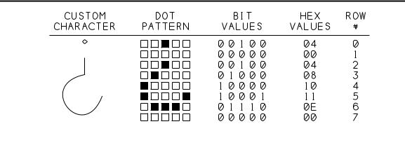
If the 192 characters provided in the CG ROM aren’t enough, you can create your own. To design a character, draw a 5 x 7 matrix and fill it with 1s where you want dots, and 0s where you want nothing. Figure 8-10 illustrates, with an example of an upside-down question mark for Spanish-language messages. Listing 8-6 creates the character and stores and displays it.
The Microcontroller Idea Book |
151 |
Chapter 8
Figure 8-10. You can create custom characters with the HD44780 controller.
The CG RAM stores the bit values for each row in the character.
For your own designs, change the values of R1-R8 in lines 401-408 to match the symbol you want.
Mounting Displays in an Enclosure
Mounting a display in an enclosure for a finished project usually involves cutting or drilling the enclosure and wiring the display to the control circuits.
For individual LEDs, you can buy inexpensive mounting rings, and drill matching holes in the enclosure’s front panel.
Seven-segment modules often mount on separate circuit boards that fit over an opening cut into the enclosure. For a more finished appearance, you can buy bezels with matching sheets of clear or tinted plastic to cover the displays and mounting hole.
Most character-based LCD modules have a mounting hole in each corner of the circuit board. You’ll need to drill matching holes in the enclosure, and cut a hole for the display to show through. Some displays have a ribbon cable attached; others have 14 holes on 0.1" centers, to which you can solder a ribbon cable or a header into which a cable plugs.
Be sure to mount your displays so they will be visible from the expected viewing angle. If necessary, tilt the display slightly in its mounting.
152 |
The Microcontroller Idea Book |

Using Sensors to Detect and Measure
9
Using Sensors to Detect and Measure
With your 8052-BASIC system and some sensors, you can detect and measure properties such as temperature, light, chemical composition, motion, and more. This chapter focuses on how to use sensors in an 8052-BASIC or other microcontroller system.
Sensor Basics
A sensor is a device that responds to a physical property or condition. Other terms for sensor are detector and transducer. Sensors enable a circuit to learn about the world outside of itself, much as humans use the senses of sight, hearing, touch, smell, and taste.
A sensor may respond in any of a number of ways. For example, litmus paper is a sensor that responds to acidity by changing color. For interfacing to the 8052-BASIC, we’re interested in sensors that respond electrically, by varying in voltage, current, or resistance, since these are easily interfaced to electronic circuits.
One obvious use for sensors is in environmental monitoring, including detecting and measuring temperature, light, wind speed and direction, humidity, and so on. But all kinds of electronic devices use sensors, even when sensing isn’t the primary purpose. For example, computer printers have sensors that detect when the printer is out of paper. Many cameras
The Microcontroller Idea Book |
153 |

Chapter 9
can sense light level and distance. And modern automobiles contain all kinds of sensors, including ones to measure engine temperature, composition of exhaust emissions, oil pressure, engine speed, and whether or not the seatbelts are fastened.
You can find a sensor to detect and measure just about any property. Some sensors are readily available from suppliers of other electronic components. These include photodiodes and solar cells, which respond to light, and semiconductors that respond to changes in temperature.
Surplus catalogs sometimes have good deals on sensors from failed or obsolete products— for example, dollar-bill sensors from vending machines and motion detectors from security systems.
Sometimes you can make your own sensors from everyday materials. The conductive foam commonly used to hold CMOS components can double as a simple pressure sensor, since its top-to-bottom resistance decreases as the foam is pressed. A popular homemade moisture detector is a printed-circuit board with two interleaved but untouching copper traces. When the board is wet, water shorts the traces together and changes the resistance between them from very high to a few hundred ohms.
Some projects call for a specialized sensor that you just won’t find in the usual sources. A good resource is the Sensors Buyer’s Guide, published annually by Sensors magazine. The guide lists over 1200 companies involved with sensors, and indexes them according to property sensed, technology used, manufacturer, and related products and services. From the list of properties sensed, you can select the category that interests you and consult a list of companies that offer products in that area. Most companies are happy to provide product information and applications hints.
Choosing Sensors
To pick the right sensor for a job, you first need to specify what you want the sensor to do. Below are some of the questions to ask about your desired sensor. The example answers describe a temperature sensor intended for use in a controller used in processing photographic film:
•What property do I want to measure? (temperature)
•What range of inputs do I need to measure? (60-110 degrees Fahrenheit)
•What resolution and accuracy do I need? (accurate to within 0.5 degree Fahrenheit)
•How fast must it respond to input changes? (quick response not critical for this application)
•What kind of output do I need (analog, digital, voltage, current,...)? (8-bit digital output would be ideal, but analog voltage or current output is OK)
154 |
The Microcontroller Idea Book |

Using Sensors to Detect and Measure
• What power supplies are available to power the sensor? (+12V, +5V)
The answers to these questions will help you narrow your choices as you research what’s available.
On/off Sensors
Sometimes, all you need to detect is the presence or absence of the sensed property. Some simple sensors act like switches, with a low resistance in the presence of the sensed property, and a high resistance in its absence.
There are many types of sensors that you can use in this way. A magnetic proximity sensor responds to the physical separation of the items connected to each of the switch elements. A vibration sensor responds to rapid motion. Both of these are often marketed as home-se- curity devices for use on doors or windows, but you might come up with other uses for them. Another example is a mercury tilt switch, which uses a ball of liquid mercury as a conductor. The switch contacts open or close when the switch tilts and the mercury rolls to the opposite end of the switch. Figure 9-1 illustrates.
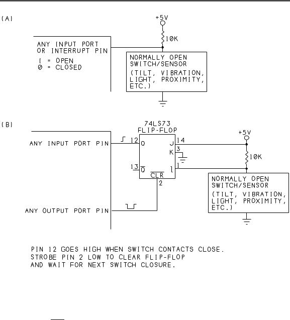
Figure 9-2 shows two ways to detect the state of on/off sensors like these.
Figure 9-2A is an unlatched input. When the resistance across the sensor is high, the pull-up resistor brings the input voltage high. When the sensor’s resistance is low, the input goes low.
You can connect this circuit to any unused pin on an input port. If you use the 8052-BASIC’s INT1 input, you can use an ONEX1 statement to trigger a subroutine whenever the sensor detects the property in question. If you use an ordinary port input, reading the port bit will tell you the current state of the sensor.
In Figure 9-2B, when the sensor switches from high to low resistance, a 74LS73 JK flip-flop stores the information as a high Q output, which your program can read at its leisure. After reading the input, strobing the CLR input low brings Q low again, until the next sensing event. The flip-flop “remembers” past events, so you don’t have to detect or respond to events as they happen.
Figure 9-1. The tilt, or physical angle, of the mercury switch determines which of its three terminals connect.
The Microcontroller Idea Book |
155 |
Chapter 9
Figure 9-2. Two ways to read the state of a normally open switch/sensor: (A) basic input, (B) latched input.
Listing 9-1 assumes that in Figure 9-1B, the Q output connects to bit 0 of an input port at E000h, and the CLR input connects to bit 0 of an output port at E400h.The program clears the flip-flop, then reads the input port continuously until the bit in question goes high. It then displays a message, clears the flip-flop, and returns to the main program.
Analog Sensors
The above sensors have just two states: on and off, or open and closed. This makes them easy to use in digital circuits, which recognize only two logic states.
156 |
The Microcontroller Idea Book |

Using Sensors to Detect and Measure
Listing 9-1. Reads and clears a flip-flop output connected to an input port pin.
10 |
REM clear flip-flop |
20 |
XBY(0E400H)=0 |
30 |
XBY(0E400H)=1 |
40 |
DO |
50 |
REM read port |
60 |
A=XBY(0E000H) |
70 |
REM see if bit 0 is set |
80 |
IF A.AND.1=1 THEN GOSUB 200 |
90 |
WHILE 1=1 |
100 |
END |
200 |
PRINT “vibration alarm” |
210 |
REM clear flip-flop |
220 |
XBY(0E400H)=0 |
230 |
XBY(0E400H)=1 |
240 |
RETI |
Many sensors have analog outputs, however. They vary continuously in response to changes in the properties they sense. For example, the resistance of a Cadmium-sulfide (CdS) photocell varies with the intensity of light hitting it. If you want to use an analog sensor like this in an 8052-BASIC system, you need to add some components to convert the analog signal to digital.
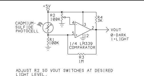
A comparator provides a way to detect a specific analog voltage. Figure 9-3 shows how to use a comparator to detect a specific light level on a photocell.
A comparator is a special form of op amp with analog inputs, but a digital output. In Figure 9-3, pin 4 is a reference voltage, and pin 5 is the input being sensed. When the sensed input is lower than the reference, the comparator’s output is low. When the sensed input is higher than the reference, the comparator’s output is high.
R1 and the photocell form a voltage divider. As the light intensity hitting the photocell increases, its resistance decreases and pin 5’s voltage rises. To detect a specific light level, adjust R2 so that VOUT switches from low to high when the light reaches the desired intensity. You can read the logic state of VOUT at any input port pin.
R4 is a pull-up resistor for the LM339’s open-collector output. R3 adds a small amount of hysteresis, which keeps the output from oscillating when the input is near the switching voltage.
The Microcontroller Idea Book |
157 |
Chapter 9
Figure 9-3. The comparator ’s output switches at the light level determined
You can use the same basic circuit with other sensors that vary in resistance. Replace the photocell with your sensor, and adjust R2 for the switching level you want. Connect VOUT to any input port pins.
Measuring Analog Signals
Sometimes you need something more sophisticated than a simple level detector. An analog-to-digital converter (ADC) enables you to measure the precise value of an analog voltage.
Some versions of the 8052 microcontroller, including Philips’ 80C562, include an on-chip ADC, but the 8052-BASIC doesn’t have this feature, so you have to add it externally. There are dozens of converters available, with varying resolution, accuracy, speed, method of conversion, number of analog inputs, and so on. Another option is to use an integrated sensor that contains its own ADC and has a digital output.
National Semiconductor’s ADC0848 is an easy-to-use, low-cost, general-purpose, eightchannel ADC. In many ways, the ADC0848 is similar to National’s long-popular ADC0808/9 A/D converters, but with some advantages. The ADC0848 does not require an external clock; its control signals interface directly to many microcontrollers; and it is faster, with a typical conversion time of 30 microseconds.
National’s data sheet for the ADC0848 has complete specifications, applications information, and example circuits. You’ll want a copy of the data sheet if you plan to use the chip.
158 |
The Microcontroller Idea Book |