

The Microcontroller Idea book (Jan Akelson, 1997)
.pdfUsing Sensors to Detect and Measure
Choosing a Converter
The ADC0848 is a good, general-purpose chip, but you may want to look at other converters, depending on your application. Below are some things to consider when choosing an A/D converter. Example answers describe the ADC0848, using information from its data sheet:
•What is the analog input range? (0V to V+)
•How many analog channels are there? (8)
•What is the converter’s resolution? (8 bits)
•How fast is the conversion? (30 microseconds typical, 60 microseceonds maximum)
•How accurate is the conversion? (±.1 LSB (least significant bit), 1/2 LSB version available)
•What are the power-supply requirements and power consumption? (+4.5 to +6V, 15 milliwatts)
•What input modes are available? (single-ended, differential, pseudo-differential)
•How is the converter controlled and interfaced? (control signals are WE, OE, CS
•Are there any special features on-chip (sample-and-hold, voltage reference, etc.)? (an internal clock times the conversions)
•What package types are available? (24-pin 0.3" DIP, 28-lead chip carrier)
Sample and Hold Circuits
An additional component that you may need for rapidly changing analog inputs is a sample-and-hold circuit. To ensure correct conversions, the analog input must not change in value while the conversion is taking place.
A sample-and-hold circuit ensures that the analog signal is stable by sampling the signal at the desired measurement time and storing it, usually as a charge on a capacitor. The converter uses this stored signal as the input to be converted.
When do you need a sample-and-hold? The ADC0848 requires 60 microseconds or less to convert, so you should get good results with inputs that do not vary more than 1 bit in this amount of time. When a rapidly changing input does require one, sample-and-hold ICs like the LF398 are available, or you can use a converter like the ADC0820, which has the sample-and-hold on-chip.
The Microcontroller Idea Book |
169 |
170 |
The Microcontroller Idea Book |

Clocks and Calendars
10
Clocks and Calendars
Many 8052-BASIC systems can make use of a real-time clock that keeps track of seconds, minutes, hours, and even days, months, and years. You can use the clock to trigger operations at specified intervals, such as every five minutes, hourly, daily, on the first of the month, or whatever. Or, a data logger might record the time and date of each measurement it takes, or the times when it detects selected events.
BASIC-52 includes its own real-time clock that counts in 5-millisecond increments. For many timing tasks, this is all you’ll need. Another approach is to add a timekeeping chip that automatically keeps track of time and calendar information. Many clocks perform functions beyond simple timekeeping, such as generating periodic interrupts or acting as a watchdog that resets the microprocessor in case of program crashes. Plus, using a separate timekeeping chip means that you don’t have to devote any of the 8052-BASIC’s resources to the task.
This chapter describes how to use both BASIC-52’s real-time clock and Dallas Semiconductor’s DS1286 Watchdog Timekeeper chip.
BASIC-52’s Real-time Clock
The 8052-BASIC, like other computers, has a timing crystal or another frequency source connected to its XTAL pins. In fact, the chip will do nothing at all without this input, since it is what clocks instructions into the chip’s CPU for execution. While this clock provides
The Microcontroller Idea Book |
171 |

Chapter 10
an essential timing reference, by itself it doesn’t keep track of real-world time measured in seconds, minutes, and hours. But if you know the crystal’s frequency, you can measure seconds by counting the oscillations of the crystal. This is what BASIC-52’s real-time clock does.
A CLOCK1 statement starts the real-time clock, which causes the TIME operator to increment every 5 milliseconds. Reading the TIME operator tells you the number of seconds that have passed since the clock was enabled. CLOCK0 stops the clock and freezes TIME at its current value. TIME resets to 0 when the count reaches 65536 seconds (18 hours, 12.3 minutes), or when the statement TIME=0 executes. If you stop the clock and then then restart it, TIME will continue counting from where it left off, unless you first reset it to 0.
The ONTIME instruction jumps to a subroutine whenever TIME reaches the value you specify. Because the ONTIME subroutine is an interrupt routine, you use RETI, not RETURN, to end it.
Listing 10-1 is a program that counts seconds, minutes, and hours, and displays the current reading once per second. For accurate timekeeping, the XTAL operator must match the value of your timing crystal.
You can also use ONTIME to trigger periodic operations. Listing 10-2 is a program that toggles bit 7 of Port 1 once per second and displays the logic state of the bit after each toggle.
Clock Accuracy
The more accurate your timing reference, the more accurate your clock will be. You can tune the frequency of a crystal slightly by varying the value of one of the capacitors that connects from the crystal to ground.
Temperature variations will cause a crystal’s frequency to drift. Crystal accuracy is rated in parts per million per degree Celsius (often shortened to ppm). Over time, a crystal rated at ±10 ppm should vary no more than 0.001 percent per degree Celsius, or 0.86 seconds per day, if the temperature varies no more than ±1 degree Celsius. If your clock must be super-accurate, choose the most stable crystal you can find and and avoid temperature fluctuations.
You might think that you can get a more accurate real-time clock by adjusting XTAL to match your crystal’s actual frequency, rather than its rated value. You could measure the crystal’s frequency with a frequency counter, or experiment by varying the value of XTAL and monitoring the real-time clock to find the best match. For example, if your 12Mhz crystal actually oscillates at 11.97 Mhz, you could set XTAL equal to 11970000.
172 |
The Microcontroller Idea Book |
|
|
|
Clocks and Calendars |
Listing 10-1. Uses BASIC-52’s real-time clock to count seconds, minutes, |
|||
and hours. |
|
|
|
10 |
REM set XTAL to match your crystal’s frequency |
||
20 |
XTAL=12000000 |
|
|
30 |
REM set and initialize clock |
|
|
40 |
GOSUB 200 |
|
|
50 |
REM increment clock variables once per minute |
||
60 |
DO |
|
|
70 |
ONTIME 60,500 |
|
|
80 |
WHILE 1=1 |
|
|
90 |
END |
|
|
200 |
PRINT “Please enter the current time:” |
||
210 |
INPUT “AM (0) or PM (1)? ”,AP |
|
|
220 |
INPUT “Hour (1-12)? ”,H |
|
|
230 |
INPUT “Minutes (0-59)? ”,M |
|
|
240 |
INPUT “Seconds (0-59)? ”,S |
|
|
250 |
REM initialize clock to current seconds |
||
260 |
TIME=S |
|
|
270 |
REM start clock |
|
|
280 |
CLOCK 1 |
|
|
290 |
RETURN |
|
|
500 |
REM increment and display time once per minute |
||
510 |
REM reset seconds |
|
|
520 |
TIME=0 |
|
|
530 |
REM increment minutes |
|
|
540 |
M=M+1 |
|
|
550 |
IF M=60 THEN |
GOSUB 700 |
|
560 |
REM display current time |
|
|
570 |
PRINT “the time is :” |
|
|
580 |
PRINT H,"hours" |
|
|
590 |
PRINT M,"minutes" |
|
|
600 |
IF AP=0 THEN |
PRINT “ AM” ELSE |
PRINT “ PM” |
610 |
RETI |
|
|
700 |
REM once/hour timekeeping |
|
|
710 |
REM reset minutes |
|
|
720 |
M=0 |
|
|
730 |
REM increment hours |
|
|
740 |
H=H+1 |
|
|
750 |
REM at 12:00, toggle am/pm |
|
|
760 |
IF H=12 THEN AP=A |
|
|
770 |
REM at 1:00, reset hours |
|
|
780 |
IF H=13 THEN H=1 |
|
|
790 |
RETURN |
|
|
The Microcontroller Idea Book |
173 |
||

Chapter |
10 |
|
Listing |
10-2. Toggles a port bit and displays the result. |
|
10 |
REM toggles P1.7 once per second |
|
20 |
TIME=0 |
|
30 |
CLOCK 1 |
|
40 |
DO |
|
50 |
ONTIME 1,100 |
|
60 |
WHILE 1=1 |
|
70 |
END |
|
100 |
REM reset time |
|
110 |
TIME=0 |
|
120 |
REM toggle Port 1, bit 7 |
|
130 |
PORT1=PORT1.XOR.80H |
|
140 |
PRINT “Port 1, bit 7 = ”,(PORT1.AND.80H)/80H |
|
150 |
RETI |
|
But in reality, because of the way that BASIC-52 calculates time, small variations in XTAL usually do not effect the real-time clock. Although BASIC-52 will store a XTAL value as precise as 12000001, it uses the same time base for all XTAL values from 11963191 to 12039877. If your crystal frequency is within this range, small adjustments to XTAL won’t make the real-time clock more accurate. The value that controls the time base is stored at 4Ah in internal data memory. At 12 Mhz, it’s 64h. If you want to experiment, change the value of XTAL, then type PH0. DBY(4AH) to find out if the time base has changed.
A Watchdog Timekeeper
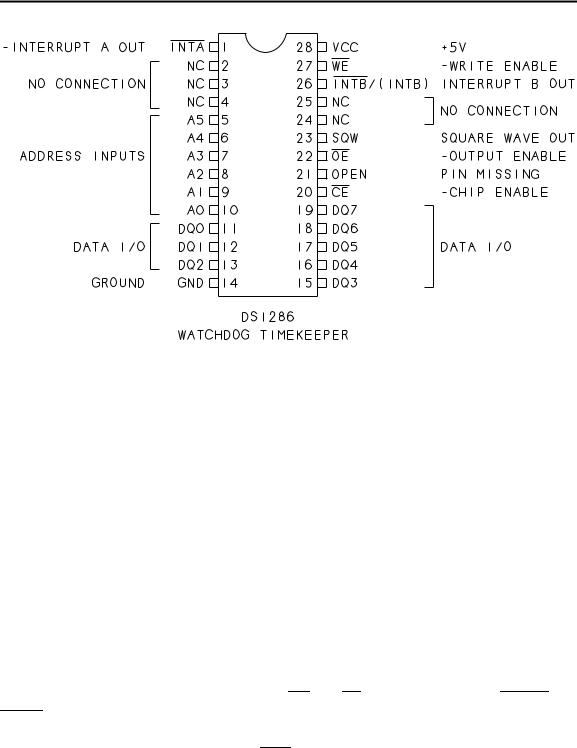
Dallas Semiconductor’s DS1286 Watchdog Timekeeper, shown in Figure 10-1, is another way to keep track of time. The chip is easy to use because it contains its own quartz-crystal timing reference, plus a lithium cell for backup power. Once you initialize the clock and calendar and start the oscillator, the clock keeps time for ten years or more, whether or not an external power source is present. You don’t have to reset the clock every time you power up.
The DS1286 can be especially useful in battery-powered systems. Since it continues to keep time when the main power supply is off, you can use its interrupt output to power circuitry at programmed times or intervals. For example, by adding circuits to control a power supply, the DS1286’s interrupt could trigger a data logger or other instrument to power up at a programmed time. After taking data or performing other operations, the instrument could power itself down until the next interrupt from the DS1286. The longer the time between readings, the greater the power savings.
174 |
The Microcontroller Idea Book |
Clocks and Calendars
Figure 10-1. Pinout of the DS1286 Watchdog Timekeeper.
The DS1286 contains a series of registers that store time, date, alarm, and configuration information. You can read the current time and date from the DS1286 in hundredths of seconds, seconds, minutes, hours, day of the week, date of the month, and year. Months of different lengths and even leap years are handled automatically. Clock accuracy is better than ±1 minute per month at 25 degrees Celsius.
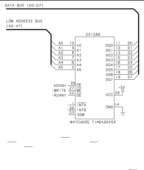
Figure 10-2 shows the pin connections for a DS1286 in a BASIC-52 system. To accommodate its crystal and power source, the DS1286 a 28-pin encapsulated DIP, just like the one used by Dallas’ NVRAMs.
The pinout and wiring are similar to that for static RAM. The chip’s access time is 150 nanoseconds, which is well within the 8052-BASIC’s timing requirements. The eight data lines (DQ0-DQ7) connect to the data bus. The chip has just six address inputs (A0-A5), which are all it needs to access its 64 bytes. The clock/calendar uses 14 bytes, and 50 bytes of nonvolatile RAM are available for any use. The chip is shown addressed at A000h, but you can use any unused chip-enable. The chip’s WE and OE inputs are driven by RDANY and
WRITE.
The DS1286 has two interrupt outputs, INTA and INTB. You can program one of these to toggle or pulse whenever the time and/or day match stored values. The other can generate an interrupt if the DS1286’s watchdog register isn’t accessed periodically. You can use this feature to automatically reset a system if a program crash causes the program to stop
The Microcontroller Idea Book |
175 |
Chapter 10
Figure 10-2. Wiring diagram for the DS1286 Watchdog Timekeeper in an 8052-BASIC system.
accessing the watchdog register. When IPSW (register B, bit 6) is 1, the time-of-day interrupt is on INTA, and the watchdog interrupt is on INTB. When IPSW is 0, these are reversed, with the watchog on INTA and the time-of-day on INTB. The chip also has a 1024-Hz square-wave output.
Table 10-1 details the functions of the DS1286’s registers, which store time, date, configuration, and status information. To initialize the clock/calendar, you write the current time and date into registers 0-2, 4, 6, and 8 through A, then start the clock by clearing EOSC (bit 7 of register 9).
Time and date values are stored in binary-coded decimal (BCD) format. In BCD, a 4-bit nibble represents one decade, and nibbles greater than 9 (1001) are not allowed. Table 10-2 shows numbers expressed in decimal, BCD, and binary. Some values in the DS1286 don’t require a full 8 bits. For example, since the month can go no higher than 12, you need only 5 bits to store its value.
176 |
The Microcontroller Idea Book |

Clocks and Calendars
Table |
10-1. |
Register functions for the DS1286 Watchdog Timekeeper |
|
||||||||||||||||||
|
|
|
|
|
|
|
|
|
|
|
|
|
|
|
|
|
|
|
|
|
|
Register |
Function |
|
|
Bit 7 |
|
Bit 6 |
Bit 5 |
Bit 4 |
Bit 3 |
Bit 2 |
Bit 1 |
Bit 0 |
|||||||||
|
|
|
|
|
|
|
|
|
|
|
|
|
|
|
|
|
|
|
|
|
|
0 |
Clock |
|
0.1 seconds |
|
|
|
|
|
|
0.01 seconds |
|
|
|||||||||
|
|
|
|
|
|
|
|
|
|
|
|
|
|
|
|
|
|
|
|
|
|
1 |
|
|
0 |
|
|
|
10 seconds |
|
|
|
seconds |
|
|
|
|||||||
|
|
|
|
|
|
|
|
|
|
|
|
|
|
|
|
|
|
|
|
|
|
2 |
|
|
0 |
|
|
|
10 minutes |
|
|
|
minutes |
|
|
|
|||||||
|
|
|
|
|
|
|
|
|
|
|
|
|
|
|
|
|
|
|
|
||
3 |
Alarm |
|
|
MASK |
|
10 minutes alarm |
|
|
|
minutes alarm |
|
|
|||||||||
|
|
|
|
|
|
|
|
|
|
|
|
|
|
|
|
|
|
|
|
|
|
4 |
Clock |
|
0 |
|
|
|
|
|
|
|
10hr or |
10hr |
hours |
|
|
|
|||||
|
|
|
12/24 |
|
|
|
|
|
|||||||||||||
|
|
|
|
|
|
|
|
|
|
|
|
AM/PM |
|
|
|
|
|
|
|
||
|
|
|
|
|
|
|
|
|
|
|
|
|
|
|
|
|
|
|
|
|
|
5 |
Alarm |
|
|
MASK |
|
|
|
|
|
10hr or |
10hr |
hour alarm |
|
|
|||||||
|
|
12/24 |
|
|
|
|
|||||||||||||||
|
|
|
|
|
|
|
|
|
|
|
|
AM/PM |
|
|
|
|
|
|
|
||
|
|
|
|
|
|
|
|
|
|
|
|
|
|
|
|
|
|
|
|
|
|
6 |
Calendar |
|
0 |
|
|
0 |
|
|
|
0 |
|
|
0 |
|
|
0 |
days |
|
|
||
|
|
|
|
|
|
|
|
|
|
|
|
|
|
|
|
|
|
|
|
|
|
7 |
Alarm |
|
|
MASK |
0 |
|
|
|
0 |
|
|
0 |
|
|
0 |
day alarm |
|
||||
8 |
Calendar, |
|
0 |
|
|
0 |
|
|
|
10 date |
|
|
|
date |
|
|
|
||||
|
Oscillator |
|
|
|
|
|
|
|
|
|
|
|
|
|
|
|
|
|
|
|
|
9 |
|
|
EOSC |
|
ESQW |
0 |
|
|
10 mo |
months |
|
|
|
||||||||
|
|
|
|
|
|
|
|
|
|||||||||||||
A |
|
|
|
10 years |
|
|
|
|
|
|
|
|
|
|
|
years |
|
|
|
||
|
|
|
|
|
|
|
|
|
|
|
|
|
|
|
|
|
|
|
|
|
|
B |
Command |
|
|
TE |
|
|
IPSW |
|
IBH/LO |
|
PU/LVL |
WAM |
TDM |
WAF |
TDF |
||||||
C |
Watchdog |
|
|
0.1 seconds |
|
|
|
|
|
|
0.01 seconds |
|
|
||||||||
|
|
|
|
|
|
|
|
|
|
|
|
|
|
|
|
|
|
|
|
|
|
D |
|
|
|
10 seconds |
|
|
|
|
|
|
seconds |
|
|
|
|||||||
|
|
|
|
|
|
|
|
|
|
|
|
|
|
|
|
|
|
|
|
|
|
E-3F |
User |
|
|
free for any use |
|
|
|
|
|
|
|
|
|
|
|||||||
|
|
|
|
|
|
|
|
|
|
|
|
|
|
|
|
|
|
|
|
|
|
Time of Day Alarm Mask Bits
|
Minutes |
Hours |
Day |
Alarm Frequency |
|||||||||
1 |
|
|
|
|
|
|
1 |
1 |
Once per minute |
||||
0 |
|
|
|
|
|
|
1 |
1 |
When minutes match |
||||
0 |
|
|
|
|
|
|
0 |
1 |
When hours and minutes match |
||||
0 |
|
|
|
|
|
|
0 |
0 |
When hours, minutes, and days match |
||||
|
|
|
|
|
|
|
|
|
|
|
|
|
|
|
Symbol |
Function |
|
Symbol |
Function |
||||||||
|
|
||||||||||||
|
|
|
|
|
|
|
|
|
|
|
|
|
|
|
|
|
|
|
|
|
|
Enable Oscillator |
|
|
|
|
Pulse/Level Triggered Interrupts |
|
EOSC |
|
|
|
|
PU/LVL |
|
||||||
|
|
|
|
|
|
Enable Square Wave Out |
WAM |
Watchdog Alarm Mask |
|||||
|
ESQW |
|
|
||||||||||
|
|
|
|
|
Transfer Enable |
|
TDM |
Time-of-day Mask |
|||||
|
TE |
|
|
|
|
|
|||||||
|
|
|
|
Interrupt Switch |
|
WAF |
Watchdog Alarm Flag |
||||||
|
IPSW |
|
|
|
|||||||||
|
|
|
|
Interrupt B High/Low Trigger |
TDF |
Time-of-day Flag |
|||||||
|
IBH/LO |
|
|||||||||||
|
|
|
|
|
|
|
|
|
|
|
|
|
|
The Microcontroller Idea Book |
177 |

Chapter 10
To generate an interrupt at a specific time, you select an alarm frequency by setting or clearing three mask bits (bit 7 of registers 3, 5, and 7), and storing the desired alarm data in bits 0-6 of the same registers. Clearing a register’s mask bit means that the DS1286 will use values in that register to determine the alarm frequency. Setting a mask bit means that the DS1286 will ignore the information in the register. For example, to generate an interrupt at 3:15 daily, you would store the following values:
Register |
Mask Byte |
Alarm Data |
|
|
|
3 |
0001 0101 |
15 minutes |
5 |
0000 0011 |
3 hours |
7 |
1XXX XXXX |
days (X=don’t care) |
Table 10-3. Decimal numbers and their equivalents in binary and binary-coded decimal. The values 0-9 are identical in BCD and binary.
Decimal |
Binary-coded Decimal (BCD) |
Binary |
0 |
0000 0000 |
0000 0000 |
1 |
0000 0001 |
0000 0001 |
2 |
0000 0010 |
0000 0010 |
3 |
0000 0011 |
0000 0011 |
4 |
0000 0100 |
0000 0100 |
5 |
0000 0101 |
0000 0101 |
6 |
0000 0110 |
0000 0110 |
7 |
0000 0111 |
0000 0111 |
8 |
0000 1000 |
0000 1000 |
9 |
0000 1001 |
0000 1001 |
10 |
0001 0000 |
0000 1010 |
11 |
0001 0001 |
0000 1011 |
|
|
|
19 |
0001 1001 |
0001 0011 |
20 |
0010 0000 |
0001 0100 |
|
|
|
29 |
0010 1001 |
0001 1101 |
30 |
0011 0000 |
0001 1110 |
|
|
|
99 |
1001 1001 |
0110 0011 |
178 |
The Microcontroller Idea Book |