

The Microcontroller Idea book (Jan Akelson, 1997)
.pdfChapter 4
Figure 4-2. Pinout for 8K EEPROM.
commands verify each byte after programming it, so the inverted data automatically keeps BASIC-52 from programming another byte until the EEPROM is ready to receive it.
Other EEPROMs have a busy output, usually at pin 1, which goes low when the EEPROM is busy. For this type, you can tie the busy output to pin 12 of U1. BASIC-52’s programming commands wait for a high logic level at this pin after programming each byte. Note that this means that pin 12 of the 8052-BASIC must be high (or not connected) during programming of any device. However, using the BUSY output is optional, since programming won’t continue until the programmed byte verifies.
Whether you choose EEPROM or NVRAM, be sure to ask for a data sheet for the device you buy, so you can verify its pinout, capacity, and timing characteristics.
Adding NVRAM or EEPROM
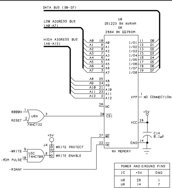
Figure 4-3 shows the added circuits for the NVRAM or EEPROM at U8. Because the circuits are an addition to Figure 3-1’s circuits, the parts continue the same numbering sequence, beginning with U8. AND gate U3C is the third gate of Figure 3-1’s U3. Table 4-1 is a parts list of the components needed to add Figure 4-3’s circuits to Figure 3-1.
50 |
The Microcontroller Idea Book |
Saving Programs
Figure 4-3. Circuits for adding NVRAM or EEPROM.
The pinout and wiring of U8 are similar to that of the RAM at U7. The data and address lines are wired exactly the same as for U7. U8 is accessed from 8000h to 9FFFh. This location is used because BASIC-52’s programming commands assume that the nonvolatile memory begins at 8000h.
OR gate U9A prevents the NVRAM or EEPROM from being accidentally overwritten during power-up. When the 8052-BASIC first powers up, its port pins are in an unknown state for a brief period, until the reset algorithm in the chip brings them all high. During this
The Microcontroller Idea Book |
51 |

Chapter 4
Table 4-1. |
Parts list for Figure 4-3. |
Semiconductors |
|
U8 |
8-kilobyte NV memory (DS1225 NVRAM or DS1213 SmartSocket with |
|
6264 SRAM or 2864 EEPROM), access time 250 nanoseconds or less |
U9 |
74HCT32 quad OR gate |
Capacitors (16WVDC, 20% tolerance) |
|
C14 |
0.1-microfarad ceramic disc |
Miscellaneous |
|
J4 |
SIP header, 3-terminal, and shorting block |
IC sockets |
|
time, there is a small chance that the right combination of outputs will cause a write operation to occur at U8.
Since this could destroy the information stored in the chip, we need a way to prevent U8 from being written to for a brief time after power-up. OR gate U9A prevents accesses to U8 until RESET goes low. The delay caused by the charging of R1 through C1 (in Figure 3-1) ensures that the reset algorithm has enough time to bring the port pins high.
U8’s Chip Select (pin 20) goes low only when both of these are true: RESET is low, and the 8052-BASIC is reading or writing to an address from 8000h to 9FFFh.
Output-enable (pin 22) connects to RDANY, to allow U8 to be accessed as data or program memory. This enables U8 to store assembly-language routines as well as BASIC-52 programs.
For writing to U8, AND gate U3C allows a choice of two control signals. WRITE is the conventional signal for writing to data memory. In addition, BASIC-52 uses a special PGM PULSE signal to store BASIC-52 programs in NV memory beginning at 8000h. Either of these signals will bring WE on U8 low.
52 |
The Microcontroller Idea Book |

Saving Programs
Jumper J4 is optional. It enables you to write-protect U8 by jumpering WE to +5V. You might want to do this if you have critical programs or data stored in U8, and you want to be sure that you don’t overwrite them accidentally.
Wiring Tips
When you add the circuits for NV memory, use sockets for U8 and U9. If you previously tied unused pins 9 and 10 of U3 to ground or +5V, be sure to remove these connections before you wire the ones shown in Figure 4-3. Since pins 4, 5, 9, 10, 12, and 13 of U9 are unused CMOS inputs, you should wire these to +5V or ground. You may instead use a 74LS32 for U9. If you do so, leave the unused inputs open.
Using the Programming Commands
When Figure 4-3’s circuit is added, you’re ready to power up and try the programming commands. Begin by entering any simple BASIC-52 program, such as one of the examples in Chapter 3.
Setting MTOP
If you have a 32K RAM at U7, you have an additional step to perform before you store a program in U8. On bootup, BASIC-52 tests contiguous memory and sets MTOP to the highest value it finds below E000h. But BASIC-52’s programming commands won’t work unless MTOP is below 8000h. To enable program storage, type the following command:
MTOP=7FFFh
This ensures that BASIC-52 won’t try to store RAM programs, variables, or strings in the area that you’ve reserved for permanent program storage (although it doesn’t prevent you from writing to the area with BASIC-52’s XBY operator). If U7 is an 8K device, MTOP is 1FFFh, well below 8000h, so you don’t have to worry about changing it.
Saving a Program
To copy the current program from U7 to U8, type
FPROG
The screen will display the number 1, indicating that this is the first BASIC-52 program to be stored in the device, and after a short delay, the READY prompt should return.
PROG is an alternate command that uses a slower programming algorithm, and should also work.
The Microcontroller Idea Book |
53 |

Chapter 4
If BASIC-52 is unable to program the chip, you’ll see this:
ERROR: PROGRAMMING
If you get this error message, double-check your wiring. When the programming command executes, pins 20, 22, and 27 should toggle, along with the address and data lines.
Running a Stored Program
When you have a program saved, you can run it from the NV memory. BASIC-52’s RAM and ROM commands switch from RAM mode, where BASIC-52 runs the program stored in RAM (U7), to ROM mode, where it looks in U8 for programs to run. When you’ve programmed successfully, run your program by typing
ROM
RUN
or
RROM
You can store multiple programs, space permitting, and run each by specifying its number. For example, to run the second program stored, type
RROM2
To return to editing programs in RAM, type
RAM
Another useful command is XFER. In ROM mode, type
XFER
to copy the current program from ROM into RAM, where you can edit it, and then use FPROG to store the revised version in U8 if you wish.
Adding Bootup Options
The commands FPROG1-FPROG6 enable you to store additional information besides programs. FPROG1 saves the current baud rate and causes BASIC-52 to boot immediately to the READY prompt, without waiting to receive a SPACE character. FPROG2 saves the current baud rate and also tells BASIC-52 to automatically run the first program in NV
54 |
The Microcontroller Idea Book |

Saving Programs
memory on bootup. This is what allows you to disconnect the system from its host and run it as a stand-alone system.
You can also permanently store a value for MTOP in U8. If you have a 32K RAM at U7, storing MTOP will ensure that you can use FPROG, and that your stored programs will be preserved when you reboot or power down.
If U7 is 32K, type
MTOP=7FFFH
FPROG3
Now, when your system boots up, MTOP will automatically be set to 7FFFh. FPROG3 also saves the baud rate and boots to the READY prompt without requiring you to press the space bar.
If you want to save MTOP and also run a program on bootup, use FPROG4, which combines the features of FPROG2 and FPROG3. FPROG5 is another useful command. It prevents BASIC-52 from clearing external data memory on bootup. FPROG6 enables you to add your own assembly-language reset routine.
If you use FPROG2-FPROG6, BASIC-52 will no longer auto-detect your host’s baud rate. You must use the baud rate and crystal value that were in use when you executed the FPROG command.
Erasing NV Memory
Eventually, your NVRAM or EEPROM will fill with programs, or you may just want to erase what you’ve stored and start fresh. Listing 4-1 is a program that erases U8 by writing 0FFh to all locations.
To use the program, enter the listing and type RUN. The READY prompt will return when erasing is complete. Line 30 verifies each erasure, and is required only for EEPROM,
Listing 4-1. Erases NVRAM or EEPROM.
10 FOR I=8000H TO 9FFFH
20 XBY(I)=0FFH
30 IF XBY(I)<>0FFH THEN GOTO 30
40 NEXT I
50 END
The Microcontroller Idea Book |
55 |

Chapter 4
because of its longer write times. The program erases all of the stored programs and any options selected with FPROG1-6 in U8.
Adding more NVRAM or EEPROM
If you want to add an additional 8K of NV RAM or EEPROM, wire another circuit exactly like Figure 4-3’s, except connect pin 20 of the new NVRAM or EEPROM to A000h (pin 10 of U4) ORed with RESET, so that the chip will be accessed from A000h to BFFFh.
Adding EPROM
Adding EPROM requires more circuitry than NVRAM or EEPROM, because an EPROM must have a programming voltage at its VPP pin during programming. To use the faster FPROG commands, which follow Intel’s Intelligent programming algorithm, you should also raise the EPROM’s supply voltage (VCC) to +6 volts during programming.
Although EPROMs do require additional components, once you have them in the circuit, you can use the 8052-BASIC system as a general-purpose EPROM programmer, as described in Chapter 13. You can store assembly-language programs or any information that you want to save in EPROM, whether it’s for use by the 8052-BASIC system or another project.
EPROM Types
Since EPROMs were first developed in the 1970’s, each generation of devices has allowed larger capacities, faster programming, and reduced programming voltages. Although the recommended programming algorithms, or procedures, for EPROMs are alike in many ways, the details often vary, depending on the device and manufacturer.
Programming Algorithms
For critical applications, there is no substitute for consulting the EPROM’s data sheet and following its recommendations exactly. But for general use, you can get reliable results with most EPROMs by using one of the two algorithms supported by BASIC-52.
50-millisecond programming. This algorithm is an older, slower procedure. To program a location in the EPROM, you apply a programming voltage to the VPP input, set the address and data lines to the desired values, and apply a 50-millisecond programming pulse at the PGM input to write the data into the EPROM at the selected address. You then increment the address, apply the new data and programming pulse, and continue in this way until all locations are programmed. After programming, you compare the EPROM’s contents to the programming data to verify that all locations programmed correctly. (BASIC-52 varies from this standard by verifying each location immediately after programming.)
56 |
The Microcontroller Idea Book |

Saving Programs
This is the recommended algorithm for older, smaller-capacity EPROMs like the 2-kilobyte 2716 and 4-kilobyte 2732, and some 8-kilobyte 2764s. These typically require a programming voltage of 21 or 25 volts at the EPROM’s VPP input.
Intelligent programming. This algorithm uses much shorter programming pulses, and verifies after each attempt. After each 1-millisecond programming pulse, you read the EPROM location to see if the programming succeeded. If not, you try again, up to 25 times. When the location verifies, you apply a final pulse equal to three times the total amount of programming pulses already applied. For example, if it takes five attempts to verify, you would apply a final 15-millisecond pulse. Finally, when all locations are programmed, you verify each once more.
For Intelligent programming, VPP is typically +12.5 volts, and VCC, the EPROM’s main power supply, is also raised from +5 to +6V during programming.
Intelligent programming is the recommended algorithm for many 8K EPROMs. Intel’s 2764 EPROM uses 21V, 5—millisecond programming, while the 2764A uses 12.5V, Intelligent programming.
Quick-pulse programming. Some CMOS 8K EPROMs (27C64) can use an even faster programming algorithm called Quick-Pulse. In Quick-Pulse programming, VPP is typically 12.75V, VCC is 6.25, and the programming pulses are 100 microseconds. BASIC-52 doesn’t offer Quick-Pulse programming as an option.
Choosing an algorithm. As a rule, you can program an EPROM using a slower algorithm than the recommended one, so you should be able to program any 12.5V EPROM with 50-millisecond programming, with VPP at 12.5V and VCC at +5V. And, any EPROM that can use Quick-Pulse programming should also program with the Intelligent or 50-millisec- ond programming algorithm and voltages. But whatever you do, don’t exceed the recommended programming voltages for the device at VCC and VPP.
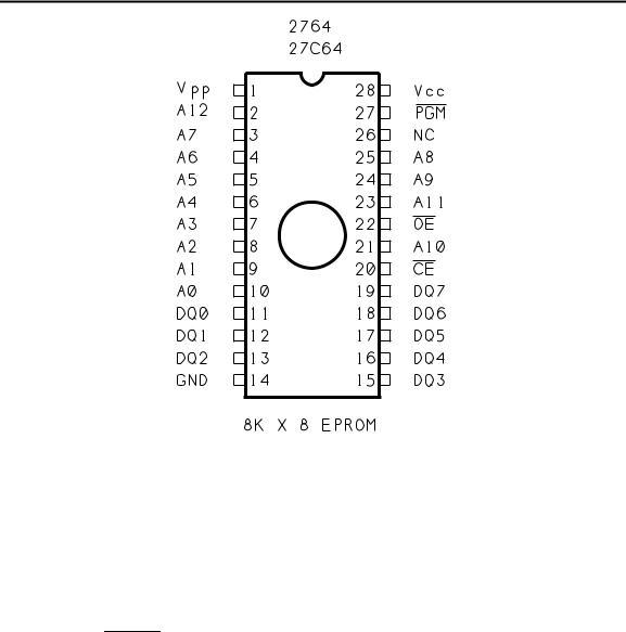
EPROM Pinouts
Figure 4-4 shows the pinout for a 2764 8K EPROM. Once again, the pin functions and locations are similar to those in an 8K RAM. During normal operation, the data pins (DQ0-DQ7) are read-only. Pin 27, which is Write Enable (WE) on RAM, is PGM, or program pulse, on the EPROM, and pin 1, which has no connection on RAM, is VPP, or programming voltage, on the EPROM.
EPROM-programming Circuits
Figure 4-5 shows additions to Figure 4-3’s circuits that enable you to program a 12.5V 8K EPROM instead of NVRAM or EEPROM. Table 4-2 is a parts list for Figure 4-5’s circuits.
The Microcontroller Idea Book |
57 |
Chapter 4
Figure 4-4. Pinout for 8K EPROM.
The components continue the numbering sequence begun in Figures 3-1 and 4-4. The additional circuits for the PROG commands are at pin 1 of U8. Jumper J5 allows you to configure the memory site for the type of NV memory you’re using.
On NVRAM or EEPROM, pin 1 has no connection (or, on some EEPROMs, it’s a BUSY output). On the EPROM, it’s VPP, which is +5V during read operations and 12.5V during programming. (pin 6 on the 8052-BASIC) controls the programming voltage by going low during programming operations and otherwise remaining high.
To prevent accidental programming during power up, OR gate U10A’s output remains high until RESET goes low. U10 is not an ordinary OR gate—it’s a 75453 peripheral driver. Unlike ordinary logic gates, U10’s open-collector output can pull up to 30V without damaging the chip. The output also has much greater current-sinking ability than other logic gates (up to 300mA), and can easily provide base current to drive transistor Q1.
When pin 3 of U10A is high, Q1 is off, and VPP connects to +5V through germanium diode D2. The diode’s voltage drop is just 0.3V, so VPP is actually at about 4.7V. Intel’s data sheets specify that read operations require VPP to be at least 3.8V for the 2764A, or VCC-0.7V for the 27C64, so 4.7V is within the specifications.
58 |
The Microcontroller Idea Book |

Saving Programs
Figure 4-5. Additional circuits for programming EPROMs.
The Microcontroller Idea Book |
59 |