The Microcontroller Idea book (Jan Akelson, 1997)
.pdf
Control Circuits
Listing 11-1. Controls an MT8808 switch matrix.
10 |
REM A=base address of 82C55 |
20 |
A=0FC00H |
30 |
REM configure 8255 for all outputs |
40 |
XBY(A+3)=80H |
50 |
REM bring MT8808’s Reset low (off) |
60 |
XBY(A+3)=0EH |
70 |
XBY(A)=0 |
80 |
DO |
90 |
INPUT “Open (0), close (1), or reset all (2)? ”,Z |
100 |
IF Z=2 THEN GOSUB 300 |
110 |
IF Z THEN GOSUB 400 |
120 |
WHILE 1=1 |
130 |
END |
290 |
REM reset all switches by toggling Reset |
300 |
XBY(A+3)=0FH |
310 |
XBY(A+3)=0EH |
320 |
RETURN |
400 |
PRINT “Enter inputs to connect or open: ” |
410 |
INPUT “X (0-7)? ”,X |
420 |
INPUT “Y (0-7)? ”,Y |
430 |
REM write to MT8808 to open or close selected switch |
440 |
B=X+Y*8+Z*40H |
450 |
XBY(A)=B |
460 |
XBY(A)=B+80H |
470 |
XBY(A)=B |
480 |
RETURN |
Listing 11-1 demonstrates switch operation by asking you whether to open or close a switch or reset them all, then performing the requested action.
Op Amp with Programmable Gain
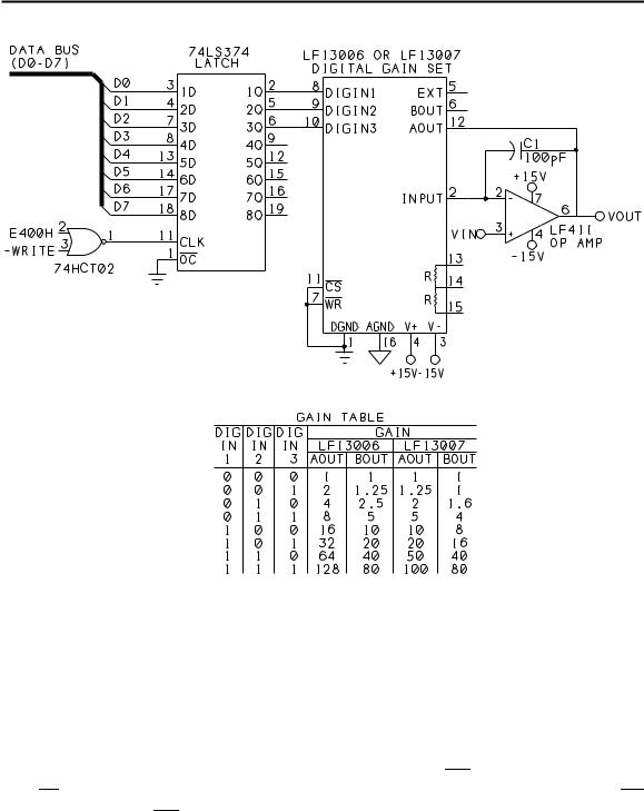
Figure 11-3 shows a way to set the gain of an operational amplifier by writing to three output port bits. Controlling the gain is National Semiconductor’s LF13006 or LF13007 digital- gain-set IC. Each contains a resistor ladder, switches, and decoding logic that enable you to select any of eight gains for an amplifier, attenuator, current source, or other circuit that requires precise, variable outputs.
Each of the gain-set ICs has two outputs, each with a different series of gains, as Figure 11-3 shows. The gain error is guaranteed to be 0.5 percent or less over the full range of operating temperatures.
The Microcontroller Idea Book |
189 |

Chapter 11
Figure 11-3. An LF13006/7 controls the gain of an LF411 op amp.
The bits that select the gain are outputs of a 74LS374 latch addressed at E400h. The LF13006/7’s Chip-Select and Write pins are tied low, which causes the gains at pins 12 and 6 to immediately match the settings at DIGIN1-DIGIN3.
If you want to control up to four gain-set chips and op amps, you can use the five remaining outputs of the 74LS374 to select the desired chip. Tie all of the WR inputs to one bit, and tie each CS input to one of the remaining bits. Then, to set the gain of an op amp, bring its CS input low, then bring WR low, then high to latch the data to the desired chip.
You can use just about any op amp with this circuit. Shown is an LF411, which has a wide bandwidth and low input offset and drift. A 10-picofarad capacitor from the op amp’s input
190 |
The Microcontroller Idea Book |

Control Circuits
Listing |
11-2. Demonstrates gain control of op amp. |
|
10 |
REM A=address of output port |
|
20 |
A=0E400H |
|
30 |
DO |
|
40 |
FOR I=0 TO 7 |
|
50 |
XBY(A)=I |
|
60 |
PRINT “Gain = ”,I |
|
70 |
PRINT “Press any key to continue...” |
|
80 |
G=GET |
|
90 |
DO |
: G=GET : UNTIL G<>0 |
100 |
NEXT I |
|
110 |
WHILE 1=1 |
|
120 |
END |
|
to output adds stability, as recommended by the LF13006/7’s data sheet. I found that the capacitor did keep the op amp’s output from oscillating at certain gain settings.
The LF13006/7 also has two matched, uncommitted resistors of about 15K each, which you can use as you wish.
Listing 11-2 steps through the available gains. You can verify circuit operation by connecting a signal such as a sine-wave output of a signal generator to VIN, and monitoring VOUT with an oscilloscope. To use the full range of gains, the signal at pin 3 must be quite small. For example, if your input is 100 millivolts peak-to-peak, at a gain of 128 the output is 12.8 volts.
Controlling a Stepper Motor
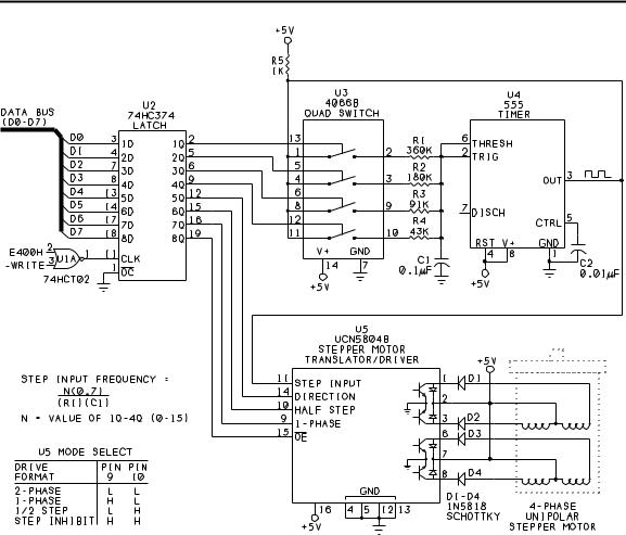
Figure 11-4 shows an 8-bit output port controlling a four-phase unipolar stepper motor. Applying power to the motor’s four phases, or coils, in sequence causes the motor to turn. The port uses a 74HCT374 latch addressed at 0E400h. If you use a 74LS374, add 10K pullups to the outputs, to ensure that logic-high inputs to U3 and U5 meet the specified minimum of 3.5V.
You can choose from several modes of operation for the motor, with each using a different sequence of pulses. The frequency and sequence of the pulses determine the speed of the motor.
In the circuit shown, after you write values to the port to set the speed and operating mode, the motor continues to run automatically, using the selected parameters. This frees the
The Microcontroller Idea Book |
191 |

Chapter 11
Figure 11-4. The UCN5804B makes it easy to control the speed, direction, and operating mode of a stepper motor.
8052-BASIC to do other things, without having to worry about generating the signals to control each step of the rotation.
The circuit uses a UCN5804B stepper-motor translator/driver (U5) from Allegro Microsystems (formerly Sprague). The chip automatically creates the drive signals for operation in any of three modes.
U3 is a 4066B CMOS quad switch that enables you to select any of 15 speeds. U4 is a 555 timer that outputs a square wave in proportion to the selected speed. U5 uses the square wave to time the steps.
U5 has four outputs that can sink up to 1.5 ampere each, and can sustain up to 35 volts. The chip includes diodes that protect against inductive transients, and thermal protection that
192 |
The Microcontroller Idea Book |

Control Circuits
disables the outputs if the chip begins to overheat. For high output currents, use a slide-on DIP heat sink to prevent overheating.
The motor is a 4-phase, unipolar type. This type of motor has six leads that connect to two sets of coils, with two coils in each set.
Surplus motors often don’t include complete documentation, but you can sort out the leads with an ohmmeter and some experimenting. Begin by looking for a lead that measures an equal resistance (typically 5 to 50 ohms) to two of the other leads. Wire this lead to +5V and pin 2 of U5. Wire the two leads that connect to this lead to pins 1 and 3 of U5 through diodes D1 and D2. Swaping the leads at pins 1 and 3 will reverse the direction of the motor. Identify and wire the remaining three leads in the same way, but using pins 6, 7, and 8 of U5.
The 5V motor is powered directly by a +5V supply. This simple drive circuit is fine for many applications, especially at lower speeds. You can find examples of other drive circuits in the documentation from Airpax or other motor manufacturers.
The data sheet for the ’5804B recommends adding D1-D4 to prevent problems in the logic circuits due to mutual coupling in the motor windings. Schottky diodes have a smaller forward voltage drop (0.25V) than other silicon diodes.
Resistors R1-R4 and capacitor C1 set the frequency of U4’s output. To select a speed, you write a number from 1 to 15 to bits 0-3 of the output port. Each bit controls one of U3’s switches. For example, when pin 2 of U2 is high, pins 1 and 2 of U3 connect, and R1 is one of U4’s timing components. When pin 2 of U2 is low, pins 1 and 2 of U3 are open, and R1 has no effect on U4. When more than one switch is closed, the parallel combination of resistors forms the timing resistance. When all switches are open, U4’s output is high and the motor stops.
In addition to the frequency of the step input, motor speed depends on the step angle of your motor and the mode selected at U5. A typical motor has a step angle of 18 degrees, which means that it requires 20 steps (360/18) for one full rotation. Using the resistor values shown and a motor with an 18-degree step angle, the motor speed will vary from 1 to 15 Hz in wave-drive or 1-phase mode.
For a different range of speeds, use the formula shown to select resistor and capacitor values. For speeds from 10 to 150 Hz, use 0.01 microfarad for C1, or decrease the values of R1-R4 by a factor of ten. The formula assumes that in the series R1-R4, each resistor is half the value of the preceding one. If you use a different resistor scaling, you’ll have to calculate the values of the parallel combinations of resistors to find the resulting frequencies.
Bits 5 and 6 of the port select the operating mode. Wave-drive mode powers one phase at a time, while two-phase drive powers two phases at once, and half-step drive alternates
The Microcontroller Idea Book |
193 |

Chapter 11
Listing 11-3. Controls a stepper motor.
10 |
REM A=address of output port |
20 |
A=0E400H |
30 |
DO |
40 |
INPUT “Speed (1-15)? ”,S |
50 |
INPUT “Mode (1=wave, 2=2-phase, 3=1/2-step, 4=stop)?”,M |
60 |
INPUT “Direction (0=Clockwise, 1=Counterclockwise)? ”,D |
70 |
IF M=1 THEN X=4 |
80 |
IF M=2 THEN X=0 |
90 |
IF M=3 THEN X=2 |
100 |
IF M=4 THEN X=6 |
110 |
XBY(A)=S+(X+D)*10H |
120 |
WHILE 1=1 |
130 |
END |
powering one and two phases. Wave drive uses the least power, but with reduced torque compared to 2-phase drive. Half-step drive uses twice as many steps per revolution, and so offers finer control.
Bit 4 (pin 12 of U2) sets the direction of rotation.
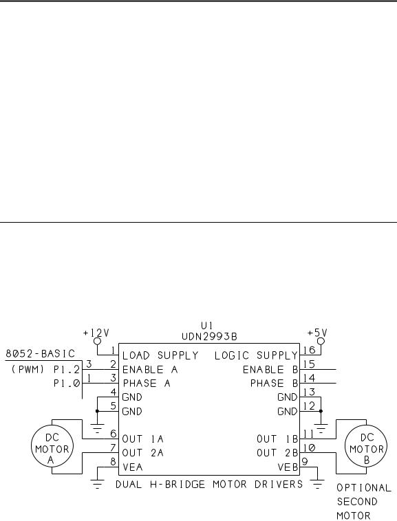
Figure 11-5. Using a UDN2993 to control a DC motor with pulse-width modulation.
194 |
The Microcontroller Idea Book |

Control Circuits
Listing 11-4. Controls direction and speed of a DC motor with BASIC-52’s PWM output.
10 |
PORT1=0FBH |
20 |
T=1 |
30 |
INPUT “Direction (0 or 1)? ”,D |
40 |
INPUT “High (on) pulse width (25 to 0FFFFh)? ”,H |
50 |
INPUT “Low (off time) pulse width (25 to 0FFFFh)? ”,L |
60 |
IF D=0 THEN PORT1=PORT1.AND.0FEH ELSE PORT1=PORT1.OR.1 |
70 |
PRINT “Press any key to end program” |
80 |
DO |
90 |
PWM H,L,T |
100 |
G=GET |
110 |
UNTIL G<>0 |
120 |
PORT1=PORT1.AND.0FBH |
130 |
END |
You can stop the motor in any of three ways. You can bring bits 0-3 of the port low to stop the timer. You can bring bit 7 high, which removes power from U4’s outputs. Or, you can bring pins 9 and 10 of U5 high, which continues to apply power to the motor, but ignores the step input.
Listing 11-3 prompts you for a motor speed, mode of operation, and direction, and then runs the motor as requested. You can stop the program, and the motor will continue to run, as long as it remains connected to the port and you don’t write anything else to it.
Speed Control of a Continuous DC Motor
If you prefer ordinary continuous dc motors to steppers, Figure 11-5 shows a circuit that uses BASIC-52’s PWM output to control motor speed.
This circuit uses another Allegro chip, the UDN2993B (U1). Pins 1 and 8 of U1 connect to the motor’s power supply, which can range from 10 to 40V. Pins 6 and 7 connect to the motor. Pin 5 is the +5V logic supply, and pins 4, 5, 12, and 13 are additional grounds. At pins 10, 11, 14, and 15, you can connect and control a second motor.
Pin 3 of U1 controls motor direction, and connects to bit 0 of Port 1 (P1.0) on the 8052-BASIC. Pin 2 of U1 switches power to the motor, with a logic low shutting the motor off, and a logic high allowing current to flow. This pin connects to Port1, bit 2 (P1.2) of the 8052-BASIC, which is the PWM output.
BASIC-52’s PWM expression causes a series of pulses to appear at P1.2, with this syntax:
The Microcontroller Idea Book |
195 |

Chapter 11
PWM high pulse width, low pulse width, number of cycles
Listing 11-4 uses the PWM output to control motor speed. The program prompts you for motor direction and the width of the high and low PWM pulses. For faster speeds, use large values for the high pulses (H) and small values for the low pulses (L). This results in a waveform with a high duty cycle, or ratio of the width of a high pulse to the width of a complete cycle (consisting of 1 high and 1 low pulse). With a high duty cycle, power is applied to the motor for a large proportion of the total time. For slower speeds, do the reverse: select small values for the high pulses and large values for the low ones, for a low duty cycle.
The actual pulse width equals the value in the PWM statement multiplied by 12, divided by the frequency of the 8052-BASIC’s timing crystal. So, with a 12-Megahertz crystal, if H=1000 and L=10,000, high pulses will be 1000 microseconds, or 1 millisecond, wide, and
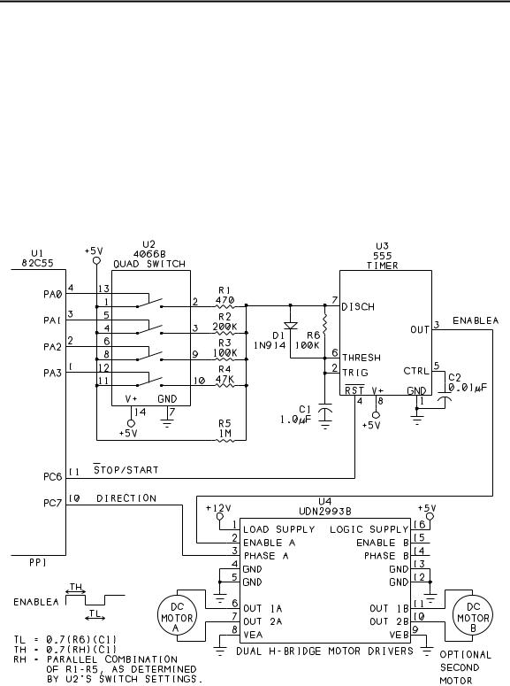
Figure 11-6. A 4066B quad switch and 555 timer enable you to select up to
16 motor speeds, with four port bits.
196 |
The Microcontroller Idea Book |
|
|
Control Circuits |
Listing 11-5. Controls |
direction and speed of Figure 11-6’s DC motor. |
|
10 |
REM A=base address of 82C55 |
|
20 |
A=0FC00H |
|
30 |
REM configure 8255 for all outputs |
|
40 |
XBY(A+3)=80H |
|
50 |
INPUT “Direction (0 or 1)? ”,D |
|
60 |
IF D=0 THEN XBY(A+3)=0EH ELSE XBY(A+3)=0FH |
|
70 |
INPUT “Speed (0-15)? ”,S |
|
80 |
XBY(A)=S |
|
90 |
REM bring 555’s Reset (PC.6) high (off) |
|
100 |
XBY(A+3)=0DH |
|
110 |
XBY(A)=S |
|
120 |
G=GET |
|
130 |
DO : G=GET : |
UNTIL G<>0 |
140 |
REM Remove 555’s Reset |
|
150 |
XBY(A+3)=0CH |
|
160 |
END |
|
|
|
|
low pulses will be 10,000 microseconds, or 10 milliseconds, wide. For accurate time calculations, set XTAL to match your crystal’s frequency.
In Listing 11-4, the number of cycles is 1, so the PWM statement results in one low pulse followed by one high pulse. Lines 100-110 then use a GET operator to check to see if the user has pressed a key and if not, the PWM output repeats. Checking for a key press enables you to stop the program, since BASIC-52 ignores CONTROL+C keypresses while a PWM statement is executing.
The DO loop in the program results in a delay between each PWM statement. During the delay, P1.2 is high, so the motor is powered. Because of the delay, with a 12-Megahertz crystal, if L=1200h and H=25, P1.2 will have equal on and off times of about 5 milliseconds. Increasing L will lower the motor’s speed, and decreasing L or increasing H will raise it.
Although you can control a second motor with the ’2993B, you get only one PWM output on the 8052-BASIC, so it’s not feasible to control two motors independently in this way.
Figure 11-6 shows another way to control the speed of a DC motor. As in Figure 11-4, the circuit uses a 4066B quad analog switch to select a timing resistance for a 555 timer. Varying the timing resistance varies the duty cycle of the 555’s output, and thus the motor’s speed.
You can select timing resistances that result in the motor speeds you want. The values shown will vary the duty cycle from about 90 to 20 percent.
The Microcontroller Idea Book |
197 |

Chapter 11
Four output bits of an 82C55 set the motor speed. Additional bits set the direction of rotation and turn the motor on and off by controlling the 555’s RESET input. You can use any output port bits to control the motor, but logic high inputs at the 4066B must be at least 3.5V, so if you use NMOS or TTL outputs, add a 10K pull-up resistor from +5V to each port output that connects to the 4066B.
Listing 11-5 asks you for a motor speed and direction, then causes the motor to spin as directed.
198 |
The Microcontroller Idea Book |
