

The Microcontroller Idea book (Jan Akelson, 1997)
.pdfUsing Sensors to Detect and Measure
Figure 9-4. The ADC0848 interfaces easily to an 8052-BASIC system, and can measure up to eight analog inputs.
Figure 9-4 shows an ADC0848 interfaced to Chapter 3’s 8052-BASIC system. The connections are similar to those used for RAM. WRITE and READ drive the converter’s WR and RD inputs. The converter is shown addressed at C000h, but you can use any unused chip-select
The Microcontroller Idea Book |
159 |

Chapter 9
line. Digital outputs DB0-DB7 connect to the data bus (D0-D7). DB0-DB4 also function as control inputs MA0-MA4.
Up to eight analog inputs can connect to pins 2-9 on the ADC0848. The voltage at VREF determines the converter’s full-scale voltage, which is the input that results in an output of 11111111, or FFh. For maximum range, connect VREF to the +5V supply or to a more precise 5-volt reference like an LM336-5.0 reference diode. The analog inputs can then range from 0 to +5 volts.
Adjusting the Range
If your sensor’s output is much less than 5 volts, you can increase the resolution of the converter by connecting VREF to a voltage slightly larger than the highest voltage you expect to measure.
To illustrate, consider a sensor whose output ranges from 0 to 0.5 volt. The 8-bit digital output of the converter represents a number from 0 to 255. If VREF is 5 volts, each count equals 5/255, or 19.6 millivolts. A 0.2-volt analog input results in a count of 10, while a 0.5-volt input results in a count of 26. If your input goes no higher than 0.5 volt, your count will never go higher than 26, and the measured values will be accurate only to within 20 millivolts, or 1/255 of full-scale.
But if you adjust VREF down to 0.5 volts, each count now equals 0.5/255, or 2 millivolts. A 0.2-volt input gives a count of 102, a 0.5-volt input gives a count of 255, and the measured values can be accurate to within 2 millivolts.
However, if you decrease VREF as described above, you also increase the converter’s sensitivity to noise. With VREF at 5 volts, a 20-millivolt noise spike will cause at most a 1-bit error in the output. If you decrease VREF to 0.5 volt, the same spike can cause an error of 10 bits, since each bit now represents 2 millivolts, not 20.
Minimizing Noise
The rapid switching of digital circuits can cause voltage spikes in the ground lines, and these can cause errors in analog measurements. Good routing of ground wires or pc-board traces can minimize noise in circuits that mix analog and digital circuits.
To minimize noise, provide separate ground paths for analog and digital signals. In Figure 9-4, this means that AGND and any ground connections related to the analog inputs or VREF should be wired together, but kept separate from the ground connections for the digital circuits, including logic chips, the 8052-BASIC, and memory chips. The two grounds are tied together at one place only, as near to the power supply as possible. The schematic uses
160 |
The Microcontroller Idea Book |

Using Sensors to Detect and Measure
different ground symbols for the two ground paths. Also be sure to include decoupling capacitors at pins 10 and 12.
Measuring Modes
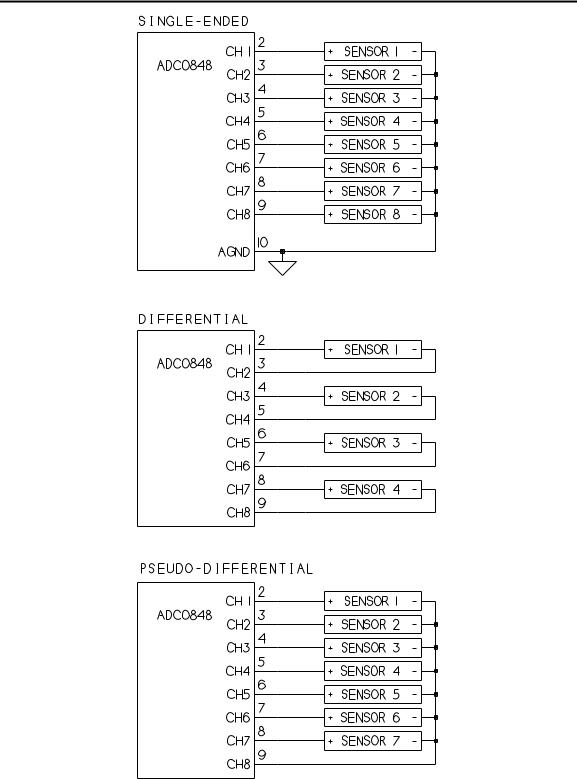
To allow for different circuit requirements, the ADC0848 offers a choice of three softwareselectable modes of operation: single-ended, differential, and pseudo-differential. Figure 9-5 illustrates.
In single-ended mode, each analog input is referenced to AGND. This is the simplest mode and will work fine for many applications.
Listing 9-2 causes the ADC to convert each of the eight channels in turn and displays the results on the host computer. For testing the circuits, you can connect a the wiper of a potentiometer to each channel, with the other two leads connecting to AGND and VREF. Verify that the readings for each channel vary from 0 to 255 as you vary the input voltage.
The other modes are useful for more critical measurements where you need to reject background noise or offset voltages.
In differential mode, each channel is paired with an adjacent one, with the voltage on one channel referenced to the voltage on the other.
For example, you could connect an output from a sensor to channel 2 and a ground or other reference from that sensor to channel 1. With differential mode selected, channel 1 will read the difference between channel 1’s and channel 2’s voltage. This mode cancels out errors due to noise that is common to both channels in the pair, such as 60-cycle power-line interference. However,because each channel uses two analog inputs, this mode limits you to four channels.
The third mode of operation is pseudo-differential. In this mode, channels 1-7 are all referenced to channel 8. This allows you to make 7 measurements, all with the same reference. This mode is useful if you are have multiple sensors in the same location. Also, if you connect channel 8 to a voltage greater than AGND, the converter’s range will shift to match, with a 0 output occurring when an input equals channel 8’s voltage.
Reading the ADC
To begin a conversion on the ADC0848, the 8052-BASIC writes to the converter indicating the desired channel and mode. Bits 0-2 specify the channel (000=1, 001=2, 010=3, etc.), and bits 3-4 specify the mode of operation (00=differential, 01=single-ended, 11=pseudo differential). So, for example, in Figure 9-4’s circuit, to begin a single-ended conversion at channel 5, you would write 0000 1101, or 0Dh, to the converter’s address.
The Microcontroller Idea Book |
161 |
Chapter 9
Figure 9-5. Measurement modes available with the ADC0848 are single-ended (A), differential (B), and pseudodifferential (C).
162 |
The Microcontroller Idea Book |

Using Sensors to Detect and Measure
Listing 9-2. Displays measurements of channels 1 through 8 on the ADC0848.
10 |
REM use single-ended mode |
20 |
REM set A to address of ADC |
30 |
A=0C000H |
40 |
FOR I=1 TO 8 |
50 |
XBY(A)=8+I-1 |
60 |
PRINT “Channel ”,I," = “, : PH0. XBY(A) |
70 |
NEXT I |
80 |
END |
Writing to the converter causes the conversion to begin automatically. When the conversion is complete, a read operation to the converter’s address causes the the converted value to appear at DB0-DB7, where the 8052-BASIC reads it.
The INTR pin indicates when a conversion is complete, and can be used to trigger a read operation. INTR is low when a conversion has occurred that has not yet been read. It goes high after a read and remains high until the next conversion is completed. BASIC-52 is slow enough that you don’t have to worry about waiting the maximum 60 microseconds between requesting a conversion and reading the result, so you can ignore INTR and read the result any time after a write.
Packaging Options
The ADC0848 comes in a 24-pin “skinny” DIP, with the pin rows spaced 0.3" apart as on a 14-pin DIP. Sockets of this size, especially wire-wrap, can be hard to find, but in a pinch you can place a 16-pin and 8-pin socket end to end. If you need only four analog inputs, use the ADC0844, in a 20-pin skinny DIP.
Sensor Examples
Now let’s look a couple of examples of sensors that you can connect to the ADC0848.
Temperature
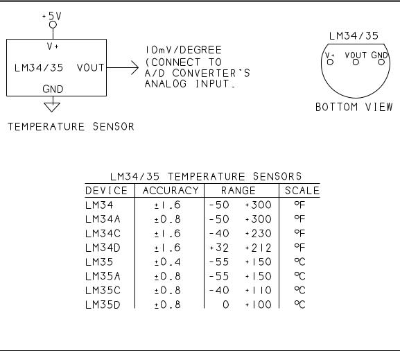
The first is an LM34 temperature sensor. Unlike many other temperature sensors, the LM34 requires no calibration. Its output is a simple 10 millivolts per degree Fahrenheit. As Figure 9-6 shows, it’s available in several versions. The ones with a narrower range or lower resolution are cheaper. If you prefer Celsius readings, use the LM35.
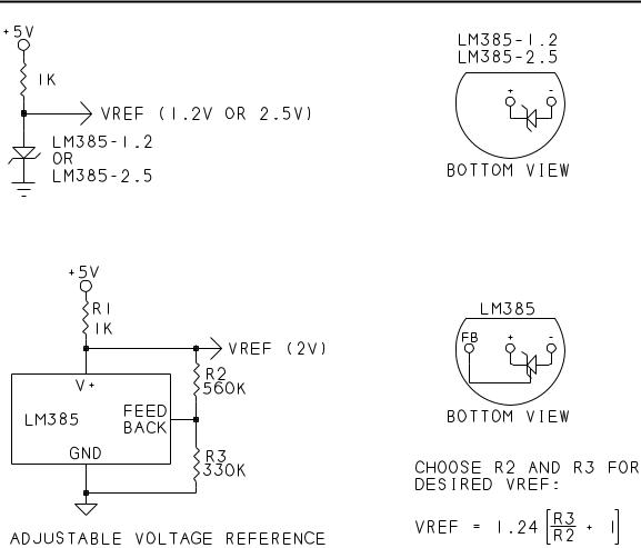
Figure 9-7 shows how to use an LM385-2.5 voltage reference to set the ADC’s VREF to 2.5V. The converter then can measure temperatures from 0 to 250 degrees, and each bit in the ADC0848’s output represents a 9.8 millivolt change in the sensor’s output.
The Microcontroller Idea Book |
163 |
Chapter 9
Figure 9-6. The LM34 and LM35 temperature sensors have outputs of 10 millivolts per degree, and need no calibration.
Listing 9-3. Measures and displays temperature reading at ADC0848’s
Channel 2.
10 |
REM set A to address of ADC |
20 |
A=0C000H |
30 |
REM use single-ended mode |
40 |
REM set C to channel to read (1-8) |
50 |
C=2 |
60 |
XBY(A)=8+C-1 |
70 |
VREF=2.5 |
80 |
B=XBY(A) |
90 |
T=INT(VREF*B*100/255+.5) |
100 |
PRINT “Temperature = ”,T |
110 |
PRINT “Press any key to take another measurement” |
120 |
D=GET : IF D=0 THEN GOTO 120 |
130 |
GOTO 60 |
140 |
END |
164 |
The Microcontroller Idea Book |
Using Sensors to Detect and Measure
Figure 9-7. The LM385 series of voltage references includes 1.2V, 2.5V, and an adjustable version.
Listing 9-3 assumes that an LM34 connects to CH2 on the ADC0848, and that VREF is 2.5V. On request, it displays the current temperature.
For a smaller range, create a 1.2V reference with an LM385-1.2 and change line 70 in the program to match. Another option is the LM385 adjustable reference, which contains a reference diode and feedback amplifier. With the addition of a voltage source and resistors in a voltage divider, you can set the LM385’s output to the reference voltage you need. Use the formula shown to vary the resistors for different outputs.
Solar Energy
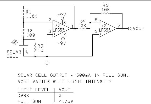
Figure 9-8 shows another sensor application, a solar cell that generates a current proportional to the intensity of the light hitting the cell. The output of the solar cell in the example varies
The Microcontroller Idea Book |
165 |
Chapter 9
Figure 9-8. VOUT varies with the light intensity, and output current, of the solar cell.
from 0 in darkness to 300 milliamperes in full sun. The voltage across the cell is about 0.5 volt.
An LF353 dual op amp converts the solar cell’s current into a voltage that the ADC0848 can measure. Most of the solar cell’s current flows through the 1-ohm resistor to ground. Since the solar cell’s voltage is only about 0.5 volt, the power dissipated by the 1-ohm resistor is only about 0.15 watt in full sun.
About one percent of the solar cell’s output flows through the 100-ohm resistor. This same current flows through the 1.6K resistor, with the result that the voltage at pin 1 of the LF353 varies from 0 to about -4.75V. This voltage is proportional to the intensity of the light hitting the solar cell. The second op amp is an inverter that converts the voltage to positive levels that the ADC0848 can measure.
Listing 9-4 assumes that pin 7 of the LF353 connects to Channel 8 of the ADC0848. On request, the program converts the analog input and displays the result.
166 |
The Microcontroller Idea Book |

Using Sensors to Detect and Measure
Listing 9-4. Measures and displays solar energy detected by solar-cell circuits at Channel 8 of ADC0848.
10 |
REM set A to address of ADC |
20 |
A=0C000H |
30 |
REM set C to channel to read (1-8) |
40 |
C=8 |
50 |
REM use single-ended mode, select channel, start convert |
60 |
XBY(A)=8+C-1 |
70 |
REM FS=full-scale voltage (5V)/full-sun output (4.75V) |
80 |
FS=1.05 |
90 |
B=XBY(A) |
100 |
T=INT(FS*B*100/255+.5) |
110 |
PRINT “Solar energy = ”,T," percent of full sun" |
120 |
PRINT “press any key to take another measurement” |
130 |
D=GET : IF D=0 THEN GOTO 130 |
140 |
GOTO 60 |
150 |
END |
Level Translating
As you can see, not every sensor has an output that can connect directly to the ADC0848’s inputs. A sensor’s output may vary from -2 to -1V, from -0.5 to +0.5V, or from -12 to +12V. In all of these cases, you need to shift the signal levels and sometimes adjust the signal range to be compatible with a converter that requires inputs between 0 and 5 volts.
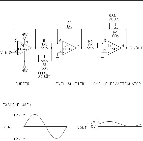
Figure 9-9 shows a general-purpose circuit that can amplify or reduce input levels, and can also raise or lower the entire signal by adding or subtracting a voltage. Separate, independent adjustments control the gain and offset. The circuit is a series of three op amps: a buffer, a level shifter, and an amplifier. The example circuit uses three of the devices in an LF347 quad JFET-input op amp. The LF347 has fast response and high input impedance. You may use a different op amp if you prefer.
The first op amp is a noninverting amplifier whose output at pin 1 equals VIN. The op amp presents a high-impedance input to VIN, to minimize loading effects.
The second op amp is an inverting summing amplifier that shifts pin 1’s voltage up or down as R5 is adjusted. Adjusting R5 raises and lowers the voltage at pin 7, but the signal’s shape and peak-to-peak amplitude remain constant.
The third op amp is an inverting amplifier whose gain is adjusted by R4. This amplifier increases or decreases the peak-to-peak amplitude of its input.
The Microcontroller Idea Book |
167 |
Chapter 9
Figure 9-9. With this circuit, you can adjust the level and amplitude of an analog signal so that it varies from 0 to +5V.
As an example of how to use the circuit, if VIN varies from +12V to -12V, adjust R4 for a ±2.5-volt swing at VOUT, then adjust R5 to raise VOUT to achieve the desired 0-to-+5V swing.
Resistor R4 can increase the gain as well as decrease it. If you need to shift the signal level down instead of up, connect R5 to +15V instead of -15V. If you don’t need level shifting, you can remove R5 and connect pin 6 only to R1 and R2.
168 |
The Microcontroller Idea Book |