

The Microcontroller Idea book (Jan Akelson, 1997)
.pdfChapter 1
abilities of the monitor program, you can load your program from a personal computer into RAM (instead of the more permanent EPROM) on the microcontroller system, then run the program, modify it, and retry as often as necessary until the program is working properly.
Most development systems also allow single-stepping, setting breakpoints, and viewing and changing the data in memory. In single-stepping, you run the program one step at time, pausing after each step, so you can more easily monitor what the circuits and program are doing at each step. A breakpoint is a program location where the program stops executing and waits for a command to continue. You can set breakpoints at critical spots in your program. At any breakpoint, you can view or change the contents of memory or perform other tests.
Simulators. Another development tool is a simulator, which is software that runs on a desktop computer and uses the video display to demonstrate what would happen if a specific microprocessor or microcontroller were to run a particular program. You can look “inside” the simulated chip, observe the contents of internal memory, and single-step or set breakpoints to stop program execution at a desired program location or condition. In this way, you can get a program working properly before you commit it to EPROM. One drawback to simulators is that they can’t mimic all features of the chip of interest, especially interrupt-response and timing characteristics.
Emulators. An in-circuit emulator (ICE) is hardware that replaces the microprocessor in question by plugging into the microprocessor’s socket on the device you want to test. Like a simulator, an emulator lets you control program execution and monitor what happens at each program step. Microprocessor emulators typically are expensive. A ROM emulator is a lower-cost option that simulates an EPROM (using RAM, for example) for program storage, and usually provides the abilities of a development system as well.
The 8052-BASIC’s development system. The 8052-BASIC system and a personal computer form a complete development system for writing, testing, and storing programs. The personal computer’s keyboard and screen make it easy to write and run programs and view the results.
BASIC-52 has many built-in debugging features that make it easy to test programs. You can run a program immediately after writing it, without having to assemble, compile, or program an EPROM. You can use a STOP statement and CONT (continue) command to set breakpoints and resume executing your program. You can use PRINT statements to display variables as the program runs. And, if you wish, you can use your personal computer for writing programs off-line and uploading and downloading them to the 8052-BASIC system.
10 |
The Microcontroller Idea Book |

Inside the 8052-BASIC
2
Inside the 8052-BASIC
This chapter introduces you to the 8052-BASIC chip, including the kinds of projects you can do with it, what equipment, materials, and skills you need in order to design and build an 8052-BASIC project, and a pin-by-pin look at the chip and its abilities.
Possibilities
The 8052-BASIC microcontroller is an easy-to-use, low-cost, and versatile computer-on-a- chip. It’s ideal for projects that require more than an assortment of logic gates, but less than a complete desktop computer system with a full keyboard, display, and disk drives. If you’re interested in doing more with computers than simply running applications programs, the 8052-BASIC gives you a chance to design and build a system from the ground up.
With a few support chips and a program stored in memory, you can use the 8052-BASIC to sense, measure, and control processes, events, or conditions. Here are just a few examples of the uses you can put it to:
•data collection
•machine control
•test equipment
•wired and wireless links for communications and control
The Microcontroller Idea Book |
11 |
Chapter 2
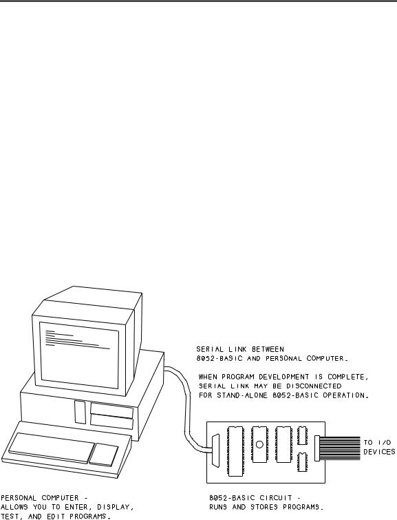
The 8052-BASIC is actually two products in one: it’s an 8052 microcontroller, with the BASIC-52 programming language on-chip. To begin using the 8052-BASIC, you need a minimum circuit consisting of the 8052-BASIC and some support components, plus a personal computer. This book contains specific instructions for use with “IBM-compatible,” or MS-DOS, computers, but you can use any computer that has an RS-232 serial port and communications software to go with it. Figure 2-1 shows the basic setup.
With an 8052-BASIC circuit connected by a serial link to a personal computer, you have a complete development system with these abilities:
•You can write and run BASIC programs. You use the keyboard, video display, and other resources of the personal computer to type and view the programs and commands that the 8052-BASIC system executes. BASIC-52 is an interpreted language whose programs do not require an additional assembling or compiling step. You can run programs or execute commands immediately after you write them.
•You can use BASIC-52’s programming functions to permanently store your programs in EPROM or other nonvolatile memory. You don’t need a separate EPROM programmer.
Figure 2-1 Setup for working with the 8052-BASIC.
12 |
The Microcontroller Idea Book |

Inside the 8052-BASIC
•You can also store programs on your personal computer’s disk. You can write or edit programs on your personal computer, and then upload them to the 8052-BASIC system.
•To the basic circuits, you can add displays, switches, keypads, relays, and other components, depending on the needs of your project.
•After program development, you can disconnect the link to the personal computer and let the 8052-BASIC system run its stored program on its own.
Limits
No single product is ideal for every use. These are some of the limitations to the 8052-BA- SIC:
•Program execution can be slow, compared with programs that run on more powerful computers, or programs written in assembly language. A typical program line in BASIC-52 takes several milliseconds to execute. Because of this, there are some tasks that BASIC-52 just can’t handle—for example, detecting and responding to an interrupt within a few microseconds. But for many control, monitoring, and other tasks, BASIC-52 is fine. For example, a weather station that senses conditions once per minute and stores or displays the results doesn’t need super-fast response. And, if necessary, you can call an assembly-language routine for a portion of a program where speed is critical.
Even if you write your programs in assembly language, C, or another language, you can use the 8052-BASIC system as a development system that enables you to upload your program to memory, run the program, and test and debug your programs and circuits.
•Another limitation of the 8052-BASIC is that a complete project requires additional components. If you’re looking for a true single-chip solution, the 8052-BASIC isn’t it. Even a minimal system requires an external RAM chip, and most systems also have an external EPROM or other non-volatile memory. The serial link and other optional functions also use some of the on-chip timers and input/output ports, so these may not be available for other uses.
Still, the 8052-BASIC lets you to do a lot with a little. When needed, you can easily add chips to expand the input/output ports, timers, and other functions.
•And finally, don’t expect BASIC-52 to have the abilities of QBasic, Visual Basic or other BASIC programming languages that you may use on your personal computer. BASIC-52 is more capable than many other single-chip BASICs. It includes features like loops, subroutines, string handling, and even floating-point math for handling
The Microcontroller Idea Book |
13 |

Chapter 2
fractional quantities. But there are some primitive aspects to the language. For example, the on-line editing functions are limited. Once you write a program line, you can change it only by retyping from the beginning. The limitations are understandable, because the entire programming language has to fit in the 8052’s 8 kilobytes of ROM. Fancy editing and other features just aren’t feasible in this small space.
There are solutions here as well. You can get around many of the editing limitations by writing and editing programs off-line, using your personal computer and text editor, and then uploading to the 8052-BASIC system. And, there are software and hardware products that enhance BASIC-52 and make it easier to use, especially for longer, more complex programming jobs.
What You Need
To use the 8052-BASIC chip, you need the following equipment, materials, and skills:
Components
The 8052-BASIC chip and supporting components are widely available. Appendix A lists sources for the components used in the circuits described in this book.
Power Supply
You’ll need a regulated +5-volt power supply to power the circuits. Output capability of at least 500 milliamperes is recommended for general experimenting. The power supply can be powered by batteries or AC line voltage, but it must have a regulated output between 4.75 and 5.25 volts.
Construction Materials
To build the circuits, you’ll need circuit-construction materials and the skills to use them. Wire-wrapping is an effective, quick way to build the circuits described, but if you prefer, you can use point-to-point soldering or design and make a printed-circuit board, or use any method that you’re comfortable with. Another option is to buy one of the available kits or prebuilt 8052-BASIC boards. You can then use this book as a guide to using and expanding the abilities of your board. Appendix A lists board suppliers and books on project-construc- tion techniques.
Documentation
Using just the information in this book, you can build and begin using your system. For serious experimenting, two additional references are recommended: programming and
14 |
The Microcontroller Idea Book |

Inside the 8052-BASIC
hardware manuals. For programming, you have two choices: Intel’s BASIC-52 User’s Manual, or Systronix’s BASIC-52 Programming. Each of these describes the BASIC-52 programming language in detail. The Intel manual includes a few schematics, while Systronix’s version has more programming examples and is better organized in general. Intel’s Embedded Microcontrollers data book is a hardware reference that describes the 8052 chip, including electrical specifications and timing requirements. It also includes an as- sembly-language reference. Appendix A tells where to get these.
Other useful documentation includes data sheets for the other components in your projects. For a small charge, many component vendors will send along data sheets for the parts you order.
Host Computer
To program the 8052-BASIC, you connect its circuits to a host computer, using an RS-232 asynchronous serial port and terminal-emulation software. The computer can be any type, as long as it has a serial port and appropriate software.
The serial port is the same connector where you plug in an external modem, serial printer, serial mouse, or other RS-232 serial device.
Terminal-emulation software is the same type of software that you may use for modem communications with an on-line BBS. Examples for MS-DOS computers are Datastorm
Table |
2-1. Differences among 8051-family chips. |
|
|||
Chip |
|
Program Memory |
|
Ram |
Timers |
|
|
|
|
(bytes) |
|
|
|
Type |
kilobytes |
|
|
|
|
|
|
||
|
|
|
|
|
|
8051 |
|
ROM |
4 |
128 |
2 |
8052 |
|
ROM |
8 |
256 |
3 |
8031 |
|
none |
- |
128 |
2 |
8032 |
|
none |
- |
256 |
3 |
8751 |
|
EPROM |
4 |
128 |
2 |
8752 |
|
EPROM |
8 |
256 |
3 |
•80C51, 80C52, 80C31, and so on are CMOS versions of above.
•80C51FA/B/C add more versatile timers and an enhanced serial channel.
•8052-BASIC has the BASIC-52 programming language in ROM.
•Packages include 40-pin DIP, 40-lead PLCC, and 44-pin QFP.
The Microcontroller Idea Book |
15 |

Chapter 2
Technologies’ Procomm Plus and the Terminal accessory in Microsoft Windows. At minimum, the software must enable you to do the following: set the baud rate and other communications parameters, serially transmit the characters that you type at the keyboard, and display the characters received at the serial port. Also useful, but not essential, is the ability to upload and download text files from your disk, over the serial link. If you don’t have a favorite communications program, look in shareware catalogs or the file areas of online services or BBS’s, where you can try out the offerings for a small disk-copying or downloading charge.
Test Equipment
Some basic test equipment will help you monitor, test, and troubleshoot your circuits. Minimum requirements include a multimeter capable of reading volts, ohms, and milliamperes. Just about any basic meter will do for this. A logic probe is convenient, but not essential, for monitoring logic levels and transitions. Best of all, an oscilloscope lets you view the actual waveforms on one or more channels.
Knowledge
This book assumes that you have a basic knowledge of electronic circuits, including digital logic. It does not assume that you know a lot about computer programming and computer circuits. Appendix A lists some books that cover the basics, if you want to review or learn these. Appendix C is a review of hexadecimal, binary, and decimal number systems.
The 8051 Family
At the core of the 8052-BASIC is an 8052 microcontroller, a member of the 8051 microcontroller family. Intel Corporation introduced the 8051 in 1980. Since that time, 8051-family chips have been used as the base of thousands of products. Many other companies, including Philips, Siemens, Dallas Semiconductor, OKI, Fujitsu, and HarrisMatra now also make 8051-family chips. Some companies have expanded the 8051 family by offering compatible chips with additional features.
Table 2-1 summarizes the differences among popular 8051-family chips. The 8052 is an enhanced 8051, with an extra timer and more RAM and ROM. The 8031 and 8032 are identical to the 8051 and 8052, except that the ROM area is unused, and program code must be stored in an external EPROM or other memory chip.
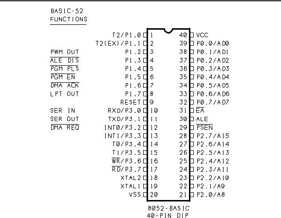
The 8052, like other 8051-family chips, is available in NMOS and CMOS versions. Figure 2-2 shows the pinout of the 8052 and 8052-BASIC, and Table 2-2 describes the pin functions.
16 |
The Microcontroller Idea Book |
Inside the 8052-BASIC
Figure 2-2 Pin functions of the 8052 and 8052-BASIC microcontrollers.
Elements of the 8052 and 8052-BASIC
These are the major elements of the 8052, plus the enhancements included in the 8052-BA- SIC:
CPU
The CPU, or central processing unit, executes program instructions. Types of instructions include arithmetic (addition, subtraction), logic (AND, OR, NOT), data transfer (move), and program branching (jump) operations. An external crystal provides a timing reference for clocking the CPU.
ROM
ROM (read-only memory) is the read-only memory that is programmed into the chip in the manufacturing process. In the 8052-BASIC, the ROM contains the BASIC-52 interpreter program that the 8052 executes on boot-up. As far as the hardware is concerned, this is the only difference between the ordinary 8052 and the 8052-BASIC.
The Microcontroller Idea Book |
17 |

Chapter 2
Table |
2-2. (page 1 of 2) Pin functions of the 8052 microcontroller and |
||||||||||
8052-BASIC additions. |
|
|
|
|
|
|
|
|
|||
Pin |
Symbol |
Input/ |
8052 |
|
8052-BASIC Additions |
||||||
|
|
Output |
Function |
|
|
|
|
|
|
|
|
|
|
|
Symbol |
Function |
|||||||
|
|
|
|
|
|||||||
|
|
|
|
|
|
|
|
|
|
|
|
1 |
P1.0 |
I/O |
Port 1, bit 0; |
|
|
|
|
|
|
|
|
|
T2 |
|
Timer 2 external input |
|
|
|
|
|
|
|
|
2 |
P1.1 |
I/O |
Port 1, bit 1; |
|
|
|
|
|
|
|
|
|
T2(EX) |
|
Timer 2 external reload/capture |
|
|
|
|
|
|
|
|
3 |
P1.2 |
I/O |
Port 1, bit 2 |
|
PWM |
Pulse-width-modulated output |
|||||
4 |
P1.3 |
I/O |
Port 1, bit 3 |
|
|
|
|
|
|
Address latch disable |
|
|
ALE DIS |
|
|
||||||||
5 |
P1.4 |
I/O |
Port 1, bit 4 |
|
|
|
|
|
|
Program pulse |
|
|
PGM PLS |
||||||||||
6 |
P1.5 |
I/O |
Port 1, bit 5 |
|
|
|
|
|
Programming voltage enable |
||
|
PGM |
|
EN |
|
|||||||
7 |
P1.6 |
I/O |
Port 1, bit 6 |
|
|
|
DMA acknowledge |
||||
|
DMA ACK |
||||||||||
8 |
P1.7 |
I/O |
Port 1, bit 7 |
|
LPT |
Line printer out |
|||||
9 |
Reset |
Input |
Reset system |
|
|
|
|
|
|
|
|
10 |
P3.0 |
I/O |
Port 3, bit 0 |
|
SER IN |
Serial port in |
|||||
|
RXD |
|
Serial receive |
|
|
|
|
|
|
|
|
11 |
P3.1 |
I/O |
Port 3, bit 1 |
|
SER OUT |
Serial port out |
|||||
|
TXD |
|
Serial transmit |
|
|
|
|
|
|
|
|
12 |
P3.2 |
I/O |
Port 3, bit 2 |
|
|
DMA request |
|||||
|
DMA |
|
|||||||||
|
INT0 |
|
External interrupt 0 |
|
REQ |
|
|||||
13 |
P3.3 |
I/O |
Port 3, bit 3 |
|
|
|
|
|
|
|
|
|
INT1 |
|
External interrupt 1 |
|
|
|
|
|
|
|
|
14 |
P3.4 |
I/O |
Port 3, bit 4 |
|
|
|
|
|
|
|
|
|
T0 |
|
Timer 0 external input |
|
|
|
|
|
|
|
|
15 |
P3.5 |
I/O |
Port 3, bit 5 |
|
|
|
|
|
|
|
|
|
T1 |
|
Timer 1 external input |
|
|
|
|
|
|
|
|
16 |
P3.6 |
I/O |
Port 3, bit 6 |
|
|
|
|
|
|
|
|
|
WR |
|
Write strobe for external |
|
|
|
|
|
|
|
|
|
|
|
memory |
|
|
|
|
|
|
|
|
17 |
P3.7 |
I/O |
Port 3, bit 7 |
|
|
|
|
|
|
|
|
|
RD |
|
Read strobe for external |
|
|
|
|
|
|
|
|
|
|
|
memory |
|
|
|
|
|
|
|
|
18 |
XTAL1 |
Input |
Inverting oscillator amplifier |
|
|
|
|
|
|
|
|
|
|
|
(crystal) |
|
|
|
|
|
|
|
|
19 |
XTAL2 |
Output |
Inverting oscillator amplifier |
|
|
|
|
|
|
|
|
|
|
|
(crystal) |
|
|
|
|
|
|
|
|
20 |
VSS |
Input |
Circuit ground |
|
|
|
|
|
|
|
|
18 |
The Microcontroller Idea Book |

Inside the 8052-BASIC
Table 2-2. (page 2 of 2)
Pin |
Symbol |
Input/ |
8052 |
8052-BASIC Additions |
||
|
|
|
|
Output |
Function |
(none on pins 21-40) |
|
|
|
|
|
|
|
|
|
|
|
|
|
|
21 |
P2.0 |
I/O |
Port 2, bit 0 |
|
||
|
A8 |
|
Address bit 8 |
|
||
22 |
P2.1 |
I/O |
Port 2, bit 1 |
|
||
|
A9 |
|
Address bit 9 |
|
||
23 |
P2.2 |
I/O |
Port 2, bit 2 |
|
||
|
A10 |
|
Address bit 10 |
|
||
24 |
P2.3 |
I/O |
Port 2, bit 3 |
|
||
|
A11 |
|
Address bit 11 |
|
||
25 |
P2.4 |
I/O |
Port 2, bit 4 |
|
||
|
A12 |
|
Address bit 12 |
|
||
26 |
P2.5 |
I/O |
Port 2, bit 5 |
|
||
|
A13 |
|
Address bit 13 |
|
||
27 |
P2.6 |
I/O |
Port 2, bit 6 |
|
||
|
A14 |
|
Address bit 14 |
|
||
28 |
P2.7 |
I/O |
Port 2, bit 7 |
|
||
|
A15 |
|
Address bit 15 |
|
||
29 |
|
|
Output |
Program store enable |
|
|
PSEN |
|
|
||||
|
|
|
|
|
Read strobe for external |
|
|
|
|
|
|
program memory |
|
30 |
ALE |
Output |
Address latch enable |
|
||
31 |
|
Input |
External access enable for |
|
||
EA |
|
|
||||
|
|
|
|
|
program memory |
|
32 |
P0.7 |
I/O |
Port 0, bit 7 |
|
||
|
AD7 |
|
Address/data bit 7 |
|
||
33 |
P0.6 |
I/O |
Port 0, bit 6 |
|
||
|
AD6 |
|
Address/data bit 6 |
|
||
34 |
P0.5 |
I/O |
Port 0, bit 5 |
|
||
|
AD5 |
|
Address/data bit 5 |
|
||
35 |
P0.4 |
I/O |
Port 0, bit 4 |
|
||
|
AD4 |
|
Address/data bit 4 |
|
||
36 |
P0.3 |
I/O |
Port 0, bit 3 |
|
||
|
AD3 |
|
Address/data bit 3 |
|
||
37 |
P0.2 |
I/O |
Port 0, bit 2 |
|
||
|
AD2 |
|
Address/data bit 2 |
|
||
38 |
P0.1 |
I//O |
Port 0, bit 1 |
|
||
|
AD1 |
|
Address/data bit 1 |
|
||
39 |
P0.0 |
I/O |
Port 0, bit 0 |
|
||
|
AD0 |
|
Address/data bit 0 |
|
||
40 |
Vcc |
Input |
Supply voltage |
|
||
The Microcontroller Idea Book |
19 |