

CHAPTER 6
Subroutines and Modules
Good software should be configured as a set of interacting modules rather than one large program working straight through from beginning to end. There are many advantages to modular programming, which is almost mandatory when code lengths exceed a few hundred lines or when a project is being developed by a team.
What form should should such modules take? In order to answer this question we will look at the use of program structures designed to facilitate this modular approach and the instructions associated with it.
After completing this chapter you will:
•Appreciate the need for modular programming.
•Have an understanding of the structure of the stack and its use in the call–return subroutine and interrupt mechanisms.
•Understand the term nested subroutine.
•See how parameters can be passed to a subroutine, by copy or reference, and altered or returned to the caller.
•Be able to write a subroutine having a minimal impact on its environment.
•Be able to synthesize a software stack to open and close a frame in the Data store to pass parameters and provide a temporary workspace.
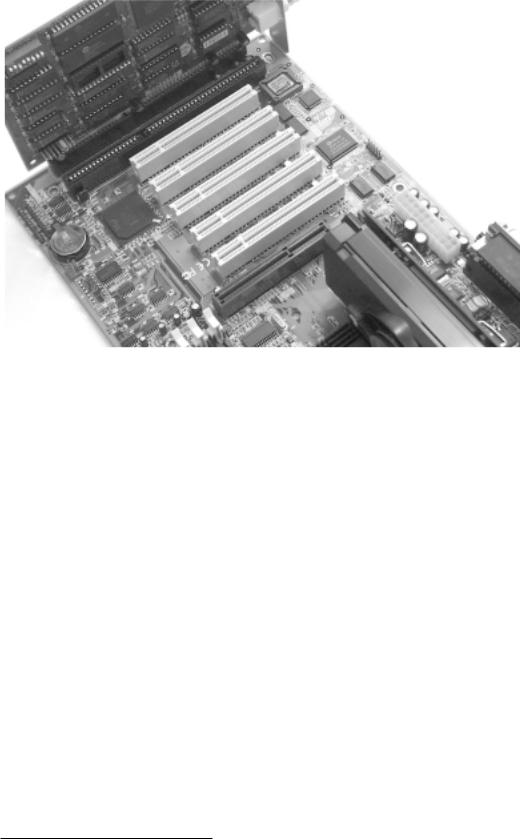
Take a look at the inside of your personal computer. It will probably look something like the photograph in Fig. 6.1, with a motherboard hosting the MPU, assorted memory and other support circuitry, and a variable number of expansion sockets. Into this will be plugged a disk controller card and a video card. There may be others, such as a soundboard, modem or network card. Each of these plug-in cards has a distinct and separate logical task and they interact via the services supplied by the main board – the motherboard.
There are many advantages to this modular construction.
•Flexibility; that is it is relatively easy to upgrade or reconfigure by adding or replacing plug-in cards.
•Can reuse from previous systems.
•Can buy in standard boards or design specialist boards in-house.
•Easy to maintain.
138 The Quintessential PIC Microcontroller
Fig. 6.1 Modular hardware implementing a PC.
Of course there are a few disadvantages. A fully integrated motherboard is smaller and potentially cheaper than an equivalent mother/daughterboard configuration. It is also likely to be more reliable, as input and output signals do not have to traverse sockets/plugs. However, when they do occur, faults are often more di cult to track down and rectify.
Modular programming uses the same principle to construct “software circuits”, i.e. programs. A formal definition of modular programming1 is:
An approach to programming in which separate logical tasks are programmed separately and joined later.
Thus to write a program in a modular fashion we need to decompose the specification into a number of stand-alone routines, each implementing a well-defined task. Such a module should be relatively short, be well documented and easy for a human, not necessarily the original programmer, to understand.
The advantages of a modular program are similar to those for modular hardware, but even more compelling:
•Each module can be tested, debugged and maintained on a stand-alone basis. This makes for overall reliability.
•Can be reused from previous projects or bought in from outside.
•Easier to update by changing modules.
1From Chambers Science and Technology Dictionary, Cambridge University Press, 1988.

6. Subroutines and Modules 139
Deciding how to segment a program into individual stand-alone tasks is where the real expertise lies. The actual coding of such tasks as subprograms is no di erent than the examples we have given in previous chapters, such as that shown in Program 5.11 on page 133. There are a few additional instructions associated with such sub-programs, and these are listed in Table 6.1. We will look at these and some useful techniques in constructing software in the remainder of the chapter.
Table 6.1: Subroutine and interrupt handling instructions.
Operation |
Mnemonic |
Description |
|
|
|
Call |
|
Transfer to subroutine |
Call subroutine |
call aaa |
Push PC on to stack, PC <- <aaa> |
Return |
|
Transfer back to caller |
from subroutine |
return |
Pull original PC back from Stack |
|
retlw |
Put literal in W and return as above |
|
|
|
Program modules may be entered by calling from other software or by a hardware event external to the processor. This may be a voltage at one of the processor pins or an internal peripheral interface wanting service, such as the Timer overflowing. In the former case modules at assembly level are universally known as subroutines, as they are in some high-level languages such as FORTRAN and BASIC.2 In the latter they are classified as interrupt service routines or interrupt handlers. The techniques for writing these interrupt modules and their entry and exit techniques are su ciently di erent to warrant a separate treatment in Chapter 7. Here we will look at subroutines.
Subroutines are the analog of hardware plug-in cards. Consider the situation where a 0.1 second (100 ms) delay task is to be implemented. This may be needed to alert an aircraft pilot to look at the control panel warning lights for various scenarios (such as low fuel or overheating) by sounding a buzzer for a short time. In a modular program, this delay would be implemented by coding a 100 ms subroutine which would be called by the main program as necessary. This is represented diagrammatically in Fig. 6.2.
In essence, calling up a subroutine involves nothing more than placing the address of the first subroutine instruction in the Program Counter (PC); that is doing a goto. Thus, if our delay subroutine were located at 400h, then goto 400h would seem to do the trick. Assuming the programmer has labelled the subroutine entry point, usually the first instruction, DELAY_100MS, as in Program 6.1, then we have goto DELAY_100MS.
2Other high-level languages use the terms function (C and Pascal) or procedure (Pascal).

140 The Quintessential PIC Microcontroller
100 ms delay
Subroutine  return
Program  call
call  More program
  call
call  Even more program
Main flow
Fig. 6.2 Subroutine calling.
The problem really is how to get back again! Somehow the MPU has to remember from where in the caller program the subroutine was entered so that it can return to the next instruction in the caller’s sequence. This can be seen in Fig. 6.2, where the jumping-o point can be from anywhere in the main program, or indeed from another subroutine – the latter process is called nesting – see Fig. 6.4.
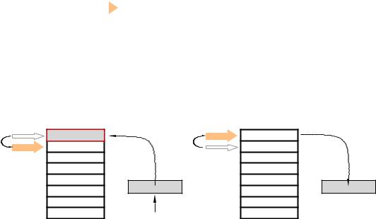
One possibility is to place this address in a designated Address register or memory location prior to jumping o . This can then be moved back into the PC at the end of the subroutine as the return mechanism. This approach breaks down whenever one subroutine wishes to call another. Then the secondary subroutine will overwrite the return address of the first, and the main program can never be regained. To get around this problem, more than one register or memory location could be used to hold a stack of return addresses. This last-in first-out stack structure is shown in Fig. 6.3(a).
The 14-bit core PICs have a stack of eight 13-bit registers which are exclusively used to hold subroutine return addresses.3 This structure, shown in Fig. 6.3, is known as a hardware stack. This stack is outside the PIC’s normal memory map, so its contents cannot be altered by any normal process.4
Associated with this stack is a 3-bit counter which points to the next available register in the stack. This Stack Pointer (SP) cannot be explicitly altered by any instruction but it is automatically incremented each time a call instruction is executed. call is similar to a goto instruction, but before the specified instruction address is put into the Program Counter the current value of PC is pushed into the stack. This is the address of the instruction after the call instruction, as the PC has already been
3The 12-bit core devices have only two 11-bit stack registers and the 16-bit core PICs have a 16-deep stack.
4Most MPU/MCUs use an area of normal RAM together with a dedicated address register to implement their stack. This is much more flexible than a dedicated hardware stack but needs a more complex instruction set to manipulate the Stack pointer and to push and pull/pop data into and out of the stack.
6. Subroutines and Modules 141
incremented and the PIC is fetching this next instruction into the pipeline at the same time as the call instruction is being executed – see Fig. 4.4 on page 87.
|
|
|
Hardware stack |
||
|
|
|
|
|
|
|
|
|
|
|
0 |
|
000b |
|
|
||
|
SP |
|
|
|
1 |
|
|
||||
|
|
|
|
|
|
|
|
|
|
|
2 |
|
|
|
|
|
3 |
|
|
|
|
|
4 |
|
|
|
|
|
5 |
|
|
|
|
|
6 |
|
|
|
|
|
7 |
(a) Before
Caller’s address |
|
|
Hardware stack |
SP |
Hardware stack |
|
|
|
Caller’s address |
000b Caller’s address |
|
001b |
|
|
SP |
|
|
PC |
|
PC |
|
|
Caller’s address |
DELAY_100MS |
|
|
(b) Calling (call DELAY_100MS) |
(c) Returning (return) |
|
Fig. 6.3 Using the hardware stack hold return addresses.
In Fig. 6.3(b) the situation is shown after a call to a subroutine labelled DELAY_100MS. The execution sequence of this call DELAY_100MS is:
1.Copy the 13-bit contents of the PC into the stack register pointed to by the Stack Pointer. This will be the address of the instruction following the call instruction.
2.The Stack Pointer is decremented.
3.The destination address DELAY_100MS, that is the location of the entry point instruction of the subroutine, overwrites the original state of the PC. E ectively this causes the program execution to transfer to the subroutine.
Apart from the pushing of the return address into the stack in steps 1 and 2, call acts exactly like a plain goto. Thus call requires two bus cycles for execution as the pipeline needs to be flushed to remove the next caller instruction which is already in situ. This similarity also applies to the extension of its 11-bit absolute address in the call instruction word to a 13-bit Program store address using bits 3 & 4 of the PCLATH register, as shown in Fig. 5.4 on page 114. Far calls to subroutines located between
142 The Quintessential PIC Microcontroller
07FFh and 1FFFh are not required for the PIC16F84 and the majority of other 14-bit core PICs that have Program store capacities of not more than 2048 instructions.
The exit point from the subroutine should be a return instruction. This reverses the push action of call and pulls the return address back from the stack into the PC – as shown in Fig. 6.3(c). The execution sequence of return is:
1.Decrement the Stack Pointer.
2.Copy the address in the stack register pointed to by the Stack Pointer into the Program Counter.
Thus no matter whence the subroutine was called form it will return to the instruction just past the original call instruction when the subroutine has been completed.
retlw (RETurn Literal value in W)5 is similar to the plain return instruction but places the specified constant byte in the Working register. Thus retlw -1 could be used to return with W set to FFh (−1 decimal) to, say, indicate an error situation. Both Return instructions flush the pipeline and therefore take two bus cycles to execute.
SR2
PC2
SR1
PC1 |
|
|
|
|
|
Main program |
|
|
|
(a) Two-deep nesting |
|
|
|
|
stack |
stack |
stack |
|
stack |
PC1 |
PC1 |
PC1 |
SP |
PC1 |
|
PC2 |
PC2 |
PC2 |
|
|
|
|||
SP |
|
SP |
|
|
|
SP |
|
|
|
(b) call SR1 |
(c) call SR2 |
(d) return |
(e) return |
|
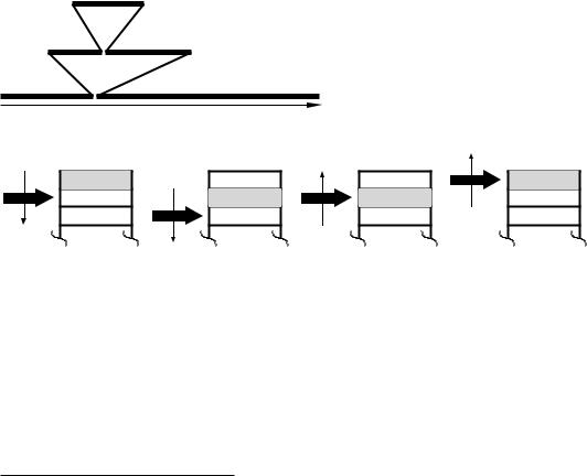
Fig. 6.4 Nested subroutines.
The beauty of the stack mechanism is its handling of nested subroutines. Consider the situation in Fig. 6.4 where the main program calls the first-level subroutine SR1 which in turn calls the second-level subroutine SR2. In order eventually to get back to the main program, the outward progression sequence must be exactly matched by the inward
5The 12-bit core PICs have only this retlw variant.
6. Subroutines and Modules 143
path. This pattern is matched by the last-in first-out (LIFO) structure of the stack mechanism, which can handle any arbitrary nesting sequence to any depth of eight subroutines automatically. It can even handle the (painful) situation where a subroutine calls itself! Such a subroutine is known as recursive. As we shall see in the next Chapter 7, the stack mechanism is also used to handle interrupts. Thus, in a system using both subroutines and interrupts the nesting depth will be somewhat less. The technique is so useful that virtually all MPU/MCUs support subroutines in this manner.
As the stack-Stack Pointer mechanism is part of the PICs hardware and requires no initialization, from the programmer’s perspective only the following points are relevant:
•The subroutine should be invoked using the call instruction.
•The entry point to a subroutine should be labelled, and this label is then the name of that subroutine.
•The exit point from the subroutine should be either return or retlw, with the latter being used when a known constant is to be in the Working register on return – see Program 6.4.
As an example, let us code the 0.1 second (100 ms) delay subroutine of Fig. 6.2. Creating a delay in software is simply a matter of doing nothing for the appropriate duration. A common way of doing this is to count down an initial constant to zero. By choosing an appropriate constant, the delay can be tailored to the desired value. Obviously, this delay will depend on the PIC’s oscillator rate. For the examples in this chapter we will assume a clock rate of 4 MHz, giving a bus cycle of 1 µs.
Consider the single-byte count code fragment:
D_LOOP decfsz |
COUNT,f |
; |
[(N-1)*1] |
+ 2 cycles |
goto |
D_LOOP |
; |
[(N-1)*2] |
cycles |
|
|
|
|
|
This continually decrements the initial setting N of the register file labelled COUNT, dropping out when it reaches zero. The total delay is contributed by both instructions as:
1.The decfsz takes one cycle to execute, except when N reaches zero, in which case two cycles are needed as the pipeline needs to be flushed
– see page 127. This gives a total execution time of [(N −1) ×1] +2.
2.As the loop exits by skipping over the goto instruction, this is only executed N − 1 times; each time taking two bus cycles. This contribution is thus (N − 1) × 2.
The total delay is thus: |
|
[(N − 1) × 1] + 2 + (N − 1) × 2 = |
[(N − 1) × 3] + 2 |
= |
(N × 3) − 1 |

144 The Quintessential PIC Microcontroller
The maximum delay is when COUNT is initialized to zero which gives an e ective value for N of 256.6 In this situation the number of cycles in this code fragment is 767, plus the few cycles calling the subroutine (2˜), clearing COUNT (1˜) and returning from the subroutine (2˜), giving a total of 772˜. With a clock rate of 4 MHz, each cycle takes 1 µs (see Fig. 4.4 on page 87) giving a total ceiling 772 µs delay.
Program 6.1 A 100 ms delay subroutine.
; ************************************************************
; * |
FUNCTION: |
Delays for around 100ms with a 4MHz crystal |
* |
||
; |
* |
ENTRY |
: |
None |
* |
; |
* |
EXIT |
: |
Flags and W altered; Files 30:1h zero |
* |
; ************************************************************
COUNT_H |
equ |
30h |
; |
2-byte counter |
COUNT_L |
equ |
31h |
; |
at File 30:1h |
Nequ d’130’ ; Delay parameter
DELAY_100MS |
|
|
|
|
movlw |
N |
; Set up high count to 130, 1˜ |
|
movwf |
COUNT_H |
; 1˜ |
|
clrf |
COUNT_L |
; and low count to 256, 1˜ |
D_LOOP |
|
|
|
|
decfsz |
COUNT_L,f |
; Decrement LS count to zero |
|
goto |
D_LOOP |
; taking in all H*[(256*3)-1]˜ |
|
decfsz |
COUNT_H,f |
; Repeat for the MS byte |
|
goto |
D_LOOP |
; taking in all (H*3)-1˜ |
FINI |
return |
|
|
|
|
|
|
Program 6.1 uses two register files to extend this count. Whenever COUNT_L has decremented to zero, COUNT_H is decremented. This inner loop takes (256 × 3) − 1 cycles in the normal way and is repeated H times, where H is the initial setting of COUNT_H. Only when this second byte reaches zero is the outer loop exited and execution returned to the caller. This second count contributes (H × 3) − 1 cycles to the total. We thus need to determine the unknown value of H to give a total of 100, 000 − 7 cycles, taking into account the call, return and the three setting up instructions.
H × [(256 × 3) − 1] + (H × 3) − 1 |
= 100, 000 − 7 |
|
767H + 3H − 1 |
= |
99, 993 |
H |
≈ |
130 |
This gives an actual delay of 100.107 ms; an error of less than 0.11%. Each incremental change in H gives an alteration of ±770 µs.
The maximum delay available with this structure is 197 ms; however, adding one or more nop instructions at the beginning of the inner loop
6If N is zero then it will decrement 00 → FF → FE → · · · 01 → 00 and exit.
6. Subroutines and Modules 145
will increase the total delay by H × 256 cycles and the same technique used in the inner loop adds H cycles for fine tuning. Example 6.3 gives an example of a very long triple count delay subroutine.
Our 100 ms delay program is an example of a double-void subroutine, in that no parameters (cf. signals in our hardware analog) are sent to it and nothing is returned – just the side e ect of a delay (and the alteration of two register files, W and some Status register flags). Most subroutines process parameters made available at entry time and provide data at return time.
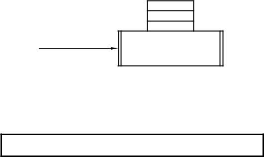
As a simple example, consider the extension of Program 6.1 to give a delay of K × 100 ms, where K is a byte parameter ‘sent’ by the caller. The system view of this function is shown in Fig. 6.5 as a single input signal of range 1– 256, with no output signal – that is with a void output. This diagram also documents the location of all local variables used internally by the subroutine. This latter attribute is useful in checking for multiple usage of a file register between di erent subroutines and callers. Notice the double line vertical borders commonly used in flow diagrams to denote modules or subroutines.
Internal workspace
COUNT_H
COUNT_L
K
File 30h
File 31h
File 32h
K (1 -- 256) in W |
DELAY_K100MS |
|
Fig. 6.5 System view of K × 100 ms delay subroutine.
As there is only one input byte-sized parameter, the most convenient place to place K is in the Working register. Thus to call up a 5-second delay, the caller could use the sequence:
movlw |
50 |
; |
50 |
x 0.1s |
gives 5 seconds |
call |
DELAY_K100MS |
; |
Go |
to it! |
|
The actual subroutine itself in Program 6.2 implements the task list:
1.DO:
(a)Delay 100ms.
(b)Decrement K.
2.WHILE (K > 0).
3.End.
The actual coding simply copies the parameter from W into File 32h before entering the following delineated coding, which is identical to Program 6.1 and gives a single 100 ms delay. On completion of the delay K

146 The Quintessential PIC Microcontroller
Program 6.2 A K × 100 ms delay subroutine.
; ************************************************************
; * |
FUNCTION: |
Delays for around |
K x 100 ms @ 4MHz |
* |
||||
; * |
EXAMPLE |
: |
K |
= 100, delays |
10 seconds |
* |
||
; |
* |
ENTRY |
: |
K |
in W, range 1 |
- |
256 |
* |
; |
* |
EXIT |
: |
Flags and W altered; Files 30:1:2h zero |
* |
|||
; ************************************************************
COUNT_H |
equ |
30h |
; 2-byte counter |
COUNT_L |
equ |
31h |
; at File 20:1h |
K |
equ |
32h |
; Temporary storage for K |
Nequ d’130’ ; Delay parameter
DELAY_K100MS |
|
|
|
|
movwf |
K |
; Put K away in a register file |
; Task 1: DO 100ms delay |
|
||
|
movlw |
N |
; Set up high count to 130 |
|
movwf |
COUNT_H |
|
|
clrf |
COUNT_L |
; and low count to 256 |
DK_LOOP |
|
|
|
|
decfsz |
COUNT_L,f |
; Decrement LS count to zero |
|
goto |
DK_LOOP |
; taking in all H*[(256*3)-1]˜ |
|
decfsz |
COUNT_H,f |
; Repeat for the MS byte |
|
goto |
DK_LOOP |
; taking in all (H*3)-1˜ |
; Task 2: Decrement K |
|
||
|
decfsz |
K,f |
|
; Task 3: WHILE |
K > 0 |
|
|
|
goto |
DK_LOOP |
; REPEAT WHILE K > 0 |
FINI |
return |
|
|
|
|
|
|
is decremented in situ and the delay block repeated until K reaches zero. Thus the 100 ms block is repeated K times.
As K is tested for zero after the 100 ms delay is executed7 an initial value of K = 0 will be treated as K = 256, giving a delay range of 00.1– 25.6 s. Testing before the loop8 would give a range 0–25.5 s. Actually, the delay will be a few µs longer than the plain 100 ms delay subroutine, due to the three additional instructions outside the delineated code block.
As W is needed to set up COUNT_H it could not be used directly to hold K during the subroutine. In fact, if the caller had known that File 32h was used by the subroutine to hold K then it could have been passed directly through this register file. However, the less the caller has to know about the ‘innards’ of its subroutines the better it will be, on the basis
7Known to C programmers as a DO-WHILE loop. 8Known to C programmers as a WHILE loop.
6. Subroutines and Modules 147
that a subroutine should disturb its environment as little as possible. DELAY_K100MS is not very good in this respect, using three file registers for its internal use and altering the Working register. As an example of what could go wrong, Program 6.3 shows an implementation of the task list but calling the 100 ms block as the existing Program 6.1 subroutine; that is a nested subroutine. Here File 30h is used as a store for K oblivious to the fact the this register file is used by subroutine DELAY_100MS as one of its counters. The e ect of this interaction is to make K zero on return from DELAY_100MS, which when decremented at Task 2 will always give a non-zero outcome. Thus the delay is infinite and the system locks up! Simply changing K equ 30h to K equ 32h fixes the problem; but if another member of the team with responsibility for the DELAY_100MS subroutine alters its internal storage map without communicating this to other team members then catastrophe may occur! Thus even though each subroutine could have been passed when tested on its own, certain combinations of calling sequences could cause failure. We will return to this problem later.
Program 6.2 is still void in that no data was returned to the caller on exit. For our next example we will code a subroutine that will activate a decimal readout. Many numeric electronic displays are based on a selective activation of seven segments in the manner shown in Fig. 6.6.
Program 6.3 An alternative K × 100 ms delay subroutine.
; ************************************************************
; * |
FUNCTION: |
Delays for around |
K x 100 ms @ 4MHz |
* |
|||||
; * |
EXAMPLE : |
K |
= 100, delays |
10 |
seconds |
* |
|||
; * |
RESOURCE: |
DELAY_100MS |
called |
|
* |
||||
; |
* |
ENTRY |
: |
K |
in W, range 1 |
- |
256 |
* |
|
; |
* |
EXIT |
: |
Flags and W |
altered; Files 30:1h zero |
* |
|||
; |
************************************************************ |
||
K |
equ |
30h |
; Temporary storage for K |
DELAY_K100MS |
|
|
|
|
movwf |
K |
; Put K away in a register file |
; Task 1: DO 100ms delay DK_LOOP call DELAY_100MS
; Task 2: Decrement K
|
decfsz |
K,f |
|
; Decrement K |
; Task 3: WHILE |
K > |
0 |
|
|
|
goto |
DK_LOOP |
; REPEAT WHILE K > 0 |
|
FINI |
return |
|
|
|
|
|
|
|
|

148 The Quintessential PIC Microcontroller
These segments are typically implemented using light-emitting diodes (see Fig. 11.13 on page 298) or electrodes in a liquid-crystal cell.
N (0 -- 9) in W
S (7-segment) in W
SVN_SEG
(a) System view
a
f b
g
e c
d
1000000 1111011 10100100 0110000 0011001 0010010 0000010 1111000 0000000 0010000
gfedcba
(b) The 7-segment font
Fig. 6.6 The 7-segment display.
The system description of our subroutine is shown in Fig. 6.6(a). Here the input signal is a 4-bit binary code representing the ten decimal digits as 0000 – 1001b in the Working register. The output, also in W, is the corresponding 7-segment code to activate the digit as listed in Table 6.2. This code assumes that a segment is lit/opaque on a binary 0 and unlit/clear on a binary 1.
Most MPU/MCUs deal with look-up tables by storing the codes as part of the program memory and copying the Nth byte out of the table as the mapping function. In the 12and 14-bit core PICs the Havard structure makes code in the Program store inaccessible to the program – but see Fig. 15.6 on page 445 for an exception. Instead, look-up tables are implemented as a series of retlw instructions, each returning a constant byte. This structure is shown in Table 6.2. As each retlw places an 8-bit code in W, I have arbitrarily made the unused bit 7 a logic 1.
In developing a coding based on this table structure, the mechanism for element N extraction is to execute the Nth retlw instruction. This will place the instruction literal in the Working register and then do a normal return form subroutine back to the caller. In the example shown, if N is seven then the 7th retlw is executed returning with the code
11111000b for 
 in W.
in W.
The coding shown in Program 6.4 implements this selection mechanism by simply adding N, which is in W, to the lower byte of the Program Counter – that is PCL in File 2. PC then points to the Nth retlw as desired.

6. Subroutines and Modules 149
Table 6.2: The 7-segment lookup table showing byte[N] being extracted.
0 |
retlw b’11000000’ |
; |
|
|
1 |
retlw b’11111001’ |
; |
|
|
|
|
|||
2 |
retlw b’10100100’ |
; |
|
|
|
|
|||
3 |
retlw b’10110000’ |
; |
|
|
|
|
|||
4 |
retlw b’10011001’ |
; |
|
|
|
|
|||
5 |
retlw b’10010010’ |
; |
|
|
|
|
|||
6 |
retlw b’10000010’ |
; |
|
|
|
|
|||
N 7 |
|
|
|
|
retlw b’11111000’ |
; |
|
= Table[N] |
|
8 |
retlw b’10000000’ |
; |
|
|
|
|
|||
9 |
retlw b’10010000’ |
; |
|
|
|
|
Although this approach does work, there are limitations. Any alteration of the PCL register will cause both these eight bits together with the lowermost five bits of the PCLATH to be moved into the 13-bit PC
– as described in Fig. 4.3 on page 86. This means that if the instruction addwf PCL,f causes the 8-bit PCL to overflow or if the contents of the PCLATH does not match the upper bits in the full PC, then the outcome stored into the PC will not be as the programmer wished – see Example 6.7. This is not easy to check, as the programmer is unlikely to know in advance where the subroutine is located in memory, that is what value the PC will have at the beginning of the subroutine. Even if he/she checks the assembler listing file (see Table 8.1 on page 206) for the value of SVN_SEG, this can change if subsequent alterations are made to other parts of the
Program 6.4 The software 7-segment decoder.
PCL |
equ |
2 |
; Low byte of PC is at File 2 |
SVN_SEG addwf |
PCL,f |
; Add N to PCL giving PC + N |
|
; |
|
xgfedcba |
|
|
retlw |
b’11000000’ |
; Code for 0 |
|
retlw |
b’11111001’ |
; Code for 1 |
|
retlw |
b’10100100’ |
; Code for 2 |
|
retlw |
b’10110000’ |
; Code for 3 |
|
retlw |
b’10011001’ |
; Code for 4 |
|
retlw |
b’10010010’ |
; Code for 5 |
|
retlw |
b’10000010’ |
; Code for 6 |
|
retlw |
b’11111000’ |
; Code for 7 |
|
retlw |
b’10000000’ |
; Code for 8 |
|
retlw |
b’10010000’ |
; Code for 9 |
|
|
|
|

150 The Quintessential PIC Microcontroller
program. It is possible to devise code to allow this address boundary to be crossed, but at the expense of complexity – see Example 6.7. The Microchip application note AN556 Implementing a Table Read gives techniques for dealing with these problems.
The code in Program 6.4 takes no account of the possibility that the datum in W is greater than 09h. Of course it shouldn’t be, but robust code should cope with all contingencies even if it is technically erroneous. This is especially true if the code module is to be reusable for general-purpose applications. What would happen if this situation arose and how could you add to the code to gracefully return an error code, say −1, in this eventuality?
Using W to transfer information to and fro a subroutine is limited to a single byte datum each way. Where several pieces of information of byte or greater sizes are to be passed, then file registers must be pressed into service for this conduit. An example of this is shown in Program 6.5 where two byte datums, labelled MULTIPLICAND and MULTIPLIER are to be multiplied giving a 16-bit outcome labelled PRODUCT_L:PRODUCT_H.
|
|
|
|
|
|
|
Internal workspace |
|
|
||
|
|
|
|
|
|
|
|
|
|
||
|
|
|
|
|
|
|
MULTIPLICAND_H |
File 30h |
|||
MULTIPLIER |
(0 -- 255) in |
File 20h |
|
|
|
|
|
PRODUCT_L:PRODUCT_H |
|
||
|
|
|
|
|
|
|
MUL |
|
|||
MULTIPLICAND |
(0 -- 255) in |
File 21h |
|
|
|
||||||
|
|
|
(0 -- 65,535) in File 2E:Fh |
||||||||
|
|
|
|
|
|
|
|
|
|
||
|
|
|
|
|
|
|
|
|
|
|
|
Fig. 6.7 System diagram for the byte multiplication subroutine.
The principle of the multiplication algorithm coded in Program 6.5 is a generalized version of that used by previous multiplication routines, such as Program 5.11 on page 133. Here the multiplier ten was decomposed to ×2+×8 which could be implemented by shifting once and three times respectively. In the more general case the multiplicand is shifted left and the nth shifted word added to the product if bit n of the multiplier is 1. Doing this eight times gives:
7
Product = (multiplicand<<n) × bit n
n=0
where the << operator denotes shift left.
Using this shift and add algorithm gives the task list:
1.Zero double-byte product.
2.Extend Multiplicand to 16 bits.
3.DO
(a)Shift Multiplier right once.
6. Subroutines and Modules 151
(b)IF Carry bit is one THEN and Multiplicand to subproduct.
(c)Shift Multiplicand right once.
(d)Repeat WHILE product not zero.
4.End with 16-bit Product.
Program 6.5 declares the variables that are passed to and from the subroutine at the of the main program. Keeping all these global declarations in one part of the program and using a di erent file register for each overall global variable reduces the possibility of interaction but at the expense of rather extravagant use of scarce Data memory resources. Temporary local storage is declared within each subroutine as its need will be ‘thrown away’ after the subroutine is terminated. However, interaction can still occur in local storage where nested subroutine structures are used.
The coding follows the task list closely. The decision whether to add the left-shifted multiplicand to the subproduct is dependent on the state of the Carry flag when the multiplier is shifted right. This implements the conditional addition
product = product + (multiplicand<<n) × bit n
Rather than implementing this shift and conditional add process eights times, the summation loop is terminated whenever the multiplier residue is zero. This means that the execution time of the subroutine is variable, depending on the bit pattern of the multiplier. The worst-case scenario is when the multiplier is 255 (11111111b). This takes 142 cycles including the two cycle call.
In order to use this subroutine, the caller copies the multiplicand into File 20h and multiplier into File 21h. On return, the 16-bit product can be read at File 2E:Fh. As an example, consider that the bytes located at File 42h and File 46h are to be multiplied.
movf |
42h,w |
; Get Number 1 |
|
movwf |
20h |
; and copy into |
MULTIPLIER |
movf |
46h,w |
; Get Number 2 |
|
movwf |
21h |
; and copy into |
MULTIPLICAND |
call |
MULT |
; Go to it! |
|
|
|
; On return the |
product is now in File 2E:Fh |
|
|
|
|
Most MPU/MCUs have software stacks which in addition to saving subroutine return addresses allow the programmer to push and pull data to and from memory to pass information between caller and subroutine. As the stack is a dynamic storage entity, growing where necessary to accommodate these passed and temporary variables and shrinking again when the subroutine terminates, this clearly is an e cient method of memory allocation. Furthermore, each call outwards in a nested structure opens a new stack frame for this dynamic storage as an extension to the

152 The Quintessential PIC Microcontroller
Program 6.5 The byte multiplication subroutine.
; Global declarations |
|
||
STATUS |
equ |
3 |
; Status register is File 3 |
C |
equ |
0 |
; Carry flag is bit0 |
Z |
equ |
2 |
; and the Zero flag is bit2 |
MULTIPLIER |
equ |
20h |
; Multiplier byte |
MULTIPLICAND |
equ |
21h |
; Multiplicand byte |
PRODUCT_L |
equ |
2Eh |
; Low byte of the product |
PRODUCT_H |
equ |
2Fh |
; High byte of the product |
;The MULT subroutine
;************************************************************
; * FUNCTION: |
Multiplies two bytes to give a 2-byte |
product |
* |
|
; * EXAMPLE : |
MULTIPLICAND = 10h, MULTIPLIER = FFh |
|
* |
|
; * EXAMPLE |
: |
PRODUCT_H:PRODUCT_L = 0FF0h (16 x 255 |
= 4080d |
* |
; * ENTRY |
: |
MULTIPLIER = File 20h, MULTIPLICAND = |
File 21h * |
|
; * EXIT |
: |
PRODUCT_H = File 2Eh, PRODUCT_L = 2Fh |
|
* |
; * EXIT |
: |
MULTIPLIER, MULTIPLICAND altered |
|
* |
; * EXIT |
: |
W, Status and MULTIPLICAND_H = File 30h altered* |
||
;************************************************************
;Local declarations
MULTIPLICAND_H equ 30h
; Task 1: Zero double-byte product MUL clrf PRODUCT_L
clrf PRODUCT_H
; Task 2: Extend multiplicand to 16 bits clrf MULTIPLICAND_H
;Task 3: DO
;Task 3A: Shift multiplier right once
MUL_LOOP bcf |
STATUS,C |
; |
Clear carry |
|
rrf |
MULTIPLIER,f |
|
|
|
; Task 3B: |
IF Carry == 1 THEN |
add multiplicand to product |
||
btfss |
STATUS,C |
; |
IF C == 1 THEN do addition |
|
goto |
MUL_CONT |
; |
ELSE skip this task |
|
movf |
MULTIPLICAND,w |
; |
DO addition |
|
addwf |
PRODUCT_L,f |
; |
First the low bytes |
|
btfsc |
STATUS,C |
; |
IF no carry THEN do high bytes |
|
incf |
PRODUCT_H,f |
; |
ELSE add carry |
|
movf |
MULTIPLICAND_H,w ; |
Next the high bytes |
||
addwf |
PRODUCT_H,f |
|
|
|
; Task 3C: |
Shift multiplicand |
right once |
||
MUL_CONT bcf |
STATUS,C |
; |
Zero Carry-in |
|
rlf |
MULTIPLICAND,f |
|
|
|
rlf |
MULTIPLICAND_H,f |
|
|
|
; WHILE multiplier not zero |
|
|
|
|
movf MULTIPLIER,f |
; |
Test multiplier for zero |
||
btfss |
STATUS,Z |
|
|
|
goto |
MUL_LOOP |
; |
IF not THEN go again |
|
return |
|
; |
ELSE finished |
|
|
|
|
|
|
6. Subroutines and Modules 153
stack. in this way the possibility of overlap between variable storage when using nested subroutines is virtually eliminated.
High-level languages, such as C (see Chapter 9) are based around this stack model, which allows the creation and passing of variables only restricted by the amount of data memory that can be allocated to this stack.
The downside to this approach is the extra CPU resources necessary to support the creation and maintenance of the stack. One or more dedicated address registers or stack pointers are normally provided and address modes that facilitate access to variables in these stack frames are needed for e cient working. Even then, the outcome is normally slower and coding is longer than models based on fixed memory allocations.
The PIC CPU does not explicitly support a software stack. However, it is possible to simulate such a structure using Indirect addressing with the File Select Register (FSR = File 4) and INDirect File (INDF = File 0) – see page 109. As there is no stack pointer register per se, in the code fragment below the main routine has allocated File 0Ch as a Pseudo Stack Pointer, which we call PSP.
; Global declarations |
|
|
||
PSP |
equ |
0Ch |
; Holds the Pseudo Stack Pointer |
|
TOS |
equ |
2Fh |
; File 2Fh is the initial Top Of Stack |
|
INDF |
equ |
0 |
; INDirect File |
|
FSR |
equ |
04 |
; File Select Register |
|
STATUS |
equ |
3 |
; Status register is File 3 |
|
C |
equ |
0 |
; Carry flag is bit0 |
|
Z |
equ |
2 |
; and the Zero flag is bit2 |
|
MULTIPLIER |
equ |
46h |
; Multiplier byte |
|
MULTIPLICAND equ |
42h |
; Multiplicand byte |
|
|
MAIN |
|
|
|
|
; In the beginning |
set up Top Of Stack |
|
||
movlw |
TOS |
|
|
|
;movwf |
PSP |
|
; which is stored in File 0Ch |
|
; |
|
|
|
|
; Sometime later when ready to call subroutine |
|
|||
movf |
PSP,w |
|
; Point FSR to top of stack frame |
|
movwf |
FSR |
|
; which is held in the PSP |
|
movf |
MULTIPLICAND,w |
; Push multiplicand out into stack |
|
|
movwf |
INDF |
|
|
|
decf |
FSR,f |
|
|
|
movf |
MULTIPLIER,w |
; Likewise for the multiplier |
|
|
movwf |
INDF |
|
|
|
decf |
FSR,f |
|
|
|
call |
MUL |
|
; Go to it |
|
; Continue on with |
the product available at FSR-3:FSR-4 |
|
||
|
|
|
|
|
The programmer also has to set aside a block of Data memory to hold the various stack frames. Here we are specifying that the Top Of Stack

154 The Quintessential PIC Microcontroller
(TOS) address is File 2Fh. If the range File 2fh–0Dh is kept clear of absolute allocations then a total of 35 bytes is available for the stack. As the hardware stack holds the subroutine return address, all locations in the simulated software stack can be used for variable passing and local storage. However, if an 8-deep subroutine nest is going to be implemented then a bigger slice of available storage may well be necessary. The software stack is initialized by moving the literal 2Fh, named TOS, into the file holding the Pseudo Stack Pointer.
As an example, consider a stack-oriented version of the multiplication subroutine of Program 6.5. A view of the software stack from the perspective of this new coding is shown in Fig. 6.8. Based on this diagram, in order to call up this subroutine the following procedure has to be implemented:
1.Push the Multiplicand and then Multiplier into the stack frame and call the subroutine.
2.Push zero into the next byte in the frame, which is being used for local storage.
3.Push zero out twice more to create an initialized hole for the two bytes to return the product.
The following code fragment shows how item 1 above is coded.
(a)Transfer the contents of the Pseudo Stack Register to the FSR. This means that the FSR now points to the top of the new stack frame. If the subroutine is a first-level call (that is not nested from another subroutine) then this will be 2Fh in our example.
Entry PSP |
Top Of Frame |
1: Before call
FSR
2: After call
FSR
3: Core of subroutine
FSR
4: New PSP
Multiplicand
Multiplier
Multiplicand_H
Product_L
Product_H
TOF
TOF-1
TOF-2
TOF-3
TOF-4
Fig. 6.8 The stack frame viewed from the perspective of subroutine MUL_S.
6. Subroutines and Modules 155
(b)Copy the Multiplicand from memory (we assume it is at File 46h as in our last example) into W and then indirectly into the frame using INDF as the target. Decrementing the FSR completes the push action.
(c)In a similar manner, the Multiplicand is pushed into the stack.
(d)Call the subroutine.
; (a) |
|
|
|
movf |
PSP,w |
; Copy current top of stack frame address |
|
movwf |
FSR |
; into the File Select register |
|
; (b) |
|
|
|
movf |
MULTIPLICAND,w |
; Push the Multiplicand into the stack |
|
movwf |
INDF |
; by copying the datum out |
|
decf |
FSR,f |
; and decrementing the FSR |
|
; (c) |
|
|
|
movf |
MULTIPLIER,w |
; Push the Multiplier into the stack |
|
movwf |
INDF |
; by copying the datum out |
|
decf |
FSR,f |
; and decrementing the FSR |
|
; (d) |
|
|
|
call |
MUL_S |
; Call the subroutine |
|
|
|
|
|
Coding of the subroutine MUL_S is given in Program 6.6. This implements items 2–4 of Fig. 6.8. Firstly, MULTIPLICAND_H, the temporary storage of the multiplicand overflow, is zeroed and then zero is pushed into the next two locations to create the initial value for the product. In item 4 the Pseudo Stack Pointer is reset to point to the next free byte below the frame. In this way, should the subroutine wish to call another, then there will be a new frame available for that next-level storage with the new TOF beginning just below the old frame. These two instructions may be omitted in this case as there are no further nested call outs, although Task 3C will have to be altered. This is done in Example 6.6.
The core of the subroutine, that is Task 3, is similar to Program 6.5 but the FSR has to be moved up and down the frame to access the appropriate level. The only non-obvious use of the FSR is at Task 3C. As there are two ways into this routine, depending on whether the shifted multiplicand is added to the product or not, the state of the FSR is unknown. It can however be reset from the PSP which is pointing to just below the frame at this point. By adding five to this PSR value, the FSR will always point to MULTIPLICAND.
Finally the subroutine ‘cleans up’ the stack by updating the Pseudo Stack Pointer to its previous value. In this case this is done by adding five, but in general by adding the frame depth n.
Program 6.6 requires 45 instructions as compared to 20 in Program 6.5. Its worst-case execution time of 274 cycles also compares unfavorably

156 The Quintessential PIC Microcontroller
with 142 cycles. Thus in all respects except reusability and robustness this stack-based model is clearly inferior. It may be more economical in
Program 6.6 Implementing a byte multiply using a stack model. (continued next page).
; ************************************************************
; * FUNCTION: |
Multiplies two |
bytes to give a |
2-byte product |
* |
|
; * EXAMPLE : |
MULTIPLICAND = |
10h, MULTIPLIER |
= FFh |
* |
|
; * EXAMPLE |
: |
PRODUCT_H:PRODUCT_L = 0FF0h (16 x 255 = 4080d |
* |
||
; * ENTRY |
: |
MULTIPLICAND = |
PSP, MULTIPLIER = PSP-1 |
* |
|
; * ENTRY |
: |
FSR points to one below MULTIPLIER |
* |
||
; * EXIT |
: |
PRODUCT_H = PSP-3, PRODUCT_L = PSP-4 |
* |
||
; * EXIT |
: |
W, Status |
|
|
* |
;************************************************************
;Tasks 1 & 2: Extend multiplicand and zero double-byte product
MUL |
clrf |
0 |
|
|
decf |
FSR,f |
; FSR ---> PRODUCT_L |
|
clrf |
0 |
|
|
decf |
FSR,f |
; FSR ---> PRODUCT_H |
|
clrf |
0 |
|
|
decf |
FSR,w |
; Now reset Pseudo Stack Pointer |
|
movwf |
PSP |
; to Bottom Of Frame |
;Task 3: DO
;Task 3A: Shift multiplier right once
incf |
FSR,f |
|
incf |
FSR,f |
|
incf |
FSR,f |
; FSR ---> MULTIPLIER |
MUL_LOOP bcf |
STATUS,C |
; Clear carry |
rrf |
0,f |
|
; Task 3B: IF Carry == 1 THEN add multiplicand to product btfss STATUS,C ; IF C == 1 THEN do addition
goto MUL_CONT ; ELSE skip this task
incf |
FSR,f |
; FSR ---> MULTIPLICAND |
movf |
0,w |
; DO addition |
decf |
FSR,f |
|
decf |
FSR,f |
|
decf |
FSR,f |
; FSR ---> PRODUCT_L |
addwf |
0,f |
; First the low bytes |
decf |
FSR,f |
; FSR ---> PRODUCT_H |
btfsc |
STATUS,C |
; IF no carry THEN do high bytes |
incf |
0,f |
; ELSE add carry |
incf |
FSR,f |
|
incf |
FSR,f |
; FSR ---> MULTIPLICAND_H |
movf |
0,w |
; Next the high bytes |
decf |
FSR,f |
|
decf |
FSR,f |
; FSR ---> PRODUCT_H |
addwf |
0,f |
|
|
|
|
6. Subroutines and Modules 157
Program 6.6 (continued.) Implementing a byte multiply using a stack model.
; Task 3C: |
Shift multiplicand right once |
|
MUL_CONT movf |
PSP,w |
; Reset FSR to the bottom of frame |
addlw |
5 |
|
movwf |
FSR |
; FSR ---> MULTIPLICAND |
bcf |
STATUS,C |
; Zero Carry-in |
rlf |
0,f |
|
decf |
FSR,f |
|
decf |
FSR,f |
; FSR ---> MULTIPLICAND_H |
rlf |
0,f |
|
; Task 3D: |
WHILE multiplier not zero |
|
incf |
FSR,f |
; FSR ---> MULTIPLIER |
movf |
0,f |
; Test multiplier for zero |
btfss |
STATUS,Z |
|
goto |
MUL_LOOP |
; IF not THEN go again |
; Task 4: End and clean up stack |
||
incf |
FSR,f |
; FSR ---> Top Of Frame |
movf |
FSR,w |
; Now reset Pseudo Stack Pointer |
movwf |
PSP |
; To TOF |
return |
|
; Finished |
|
|
|
its use of scarce data memory in large software systems. However, in programs running on low and mid-range PICs are often not very complex. Furthermore the small Program memory (1024 instructions for the PIC16F84) may further restrict the use of this relatively extravagant technique. Where real-time execution time is critical the additional burden of stack handling is unlikely to be worthwhile.
Examples
Example 6.1
The binary series approximation to the fraction 13 is:
1 1 1 1 1 1 1 1 3 = 2 − 4 + 8 − 16 + 32 − 64 + 128 · · ·
Using this series, write a subroutine that will divide a byte in the Working register by three with the quotient being returned in the same W register. The actual value of the summation up to 1281 is 0.3359375, which is within 0.78% of the exact value. With an 8-bit datum there is no point in including any further elements in the series, but where 16-bit operands are being processed then further elements up to the desired accuracy can be summed in the same manner.

158 The Quintessential PIC Microcontroller
Solution
The fractions 12 , 14 , 18 etc. can be easily generated by shifting right. The coding listed in Program 6.7 simply repetitively shifts the number as copied to a temporary location in register file File 33h right. Notice that it is necessary to clear the Carry flag before each shift as both the previous Rotate and Subtract instructions can alter its state. As the subwf instruction subtracts the contents of W (the sub quotient) from the datum in the specified file register then the outcome being built up in W will oscillate in sign as desired. In situations where the series element signs
Program 6.7 Dividing by three
; ************************************************************
; * |
FUNCTION: |
Divides a 16-bit word by three |
* |
||||
; * |
EXAMPLE |
: |
Dividend = FFh (255d), Quotient = 55h (85d) |
* |
|||
; * |
ENTRY |
: |
Dividend N |
in W |
* |
||
; |
* |
EXIT |
: |
Quotient |
Q |
= N in W |
* |
; |
* |
EXIT |
: |
File 33h |
altered |
* |
|
;************************************************************
;Local declarations
DIV_TEMP equ 33h |
; |
Temporary work byte |
|
DIV_3 movwf |
DIV_TEMP |
; |
Copy N into memory |
movlw |
0 |
; |
Clear quotient |
bcf |
STATUS,C |
; |
Clear Carry flag |
rrf |
DIV_TEMP,f ; |
N/2 |
|
movf |
DIV_TEMP,w |
; |
Q = N(1/2) |
bcf |
STATUS,C |
; |
Clear Carry flag |
rrf |
DIV_TEMP,f ; |
N/4 |
|
subwf |
DIV_TEMP,w |
; |
Q = N/4-Q = N(+1/4-1/2) |
bcf |
STATUS,C |
; |
Clear Carry flag |
rrf |
DIV_TEMP,f ; |
N/8 |
|
subwf |
DIV_TEMP,w |
; |
Q = N/8-Q = N(1/8-1/4+1/2) |
bcf |
STATUS,C |
; |
Clear Carry flag |
rrf |
DIV_TEMP,f ; |
N/16 |
|
subwf |
DIV_TEMP,w |
; |
Q = N/16-Q = N(1/16-1/8+1/4-1/2) |
bcf |
STATUS,C |
; |
Clear Carry flag |
rrf |
DIV_TEMP,f ; |
N/32 |
|
subwf |
DIV_TEMP,w |
; |
Q = N/32-Q = N(1/32-1/16+1/8-1/4+1/2) |
bcf |
STATUS,C |
; |
Clear Carry flag |
rrf |
DIV_TEMP,f ; |
N/64 |
|
subwf |
DIV_TEMP,w |
; |
Q = N(1/64-1/32+1/16-1/8+1/4-1/2) |
bcf |
STATUS,C |
; |
Clear Carry flag |
rrf |
DIV_TEMP,f ; |
N/128 |
|
subwf |
DIV_TEMP,w ; |
Q = N(1/128-1/64+1/32-1/16+1/8-1/4+1/2) |
|
return |
|
; |
Return with quotient in W |
|
|
|
|

6. Subroutines and Modules 159
are not so regular then a further file register must be used to build up the quotient. The coding in Program 6.7 can be considered as the shift and subtract analog of the shift and add process outlined in Program 6.5 above. Execution takes 27 cycles including call and return. It can easily be extended to generate the fraction 23 by omitting the first shift right, thereby e ectively multiplying the series by two. The rest of the program remains the same.
Example 6.2
Write a subroutine to give a fixed 208 µs delay. Assume a 4 MHz processor clock rate.
Solution
For a short time period like this the code fragment of page 143 provides adequate delay. The solution shown in Program 6.8 is identical to this coding terminated by a return instruction.
Program 6.8 Coding a 208 µs delay.
COUNT |
equ |
34h |
; Temp location to hold count down |
|
N |
equ |
d’67’ |
; The delay parameter is decimal 67 |
|
DELAY_208 movlw |
N |
; The delay parameter, 1˜ |
||
|
movwf |
COUNT |
; Stored in File 34h , 1˜ |
|
D_LOOP |
decfsz |
COUNT,f |
; [(N-1)*1] + 2 cycles |
|
|
goto |
D_LOOP |
; [(N-1)*2] cycles |
|
|
return |
|
; Finish |
, 2˜ |
|
|
|
|
|
In order to calculate the parameter the time equation is:
2(call) + 1 + 1 + (N × 3 − 1) + 2 |
= |
208 µs |
N × 3 |
= |
203 |
N |
= |
67 |
This gives a total delay of 206 µs. Adding two nop instructions just before the return instruction will add the two extra µs.
See Program 12.10 on page 338.
Example 6.3
At the other end of the spectrum write a subroutine to give a delay of one second.

160 The Quintessential PIC Microcontroller
Solution
For a delay as long as this we need to extend Program 6.1 to use a larger count. In the coding of Program 6.9 three file registers are used to give a triple loop.
File register COUNT2 is initialized to the value H whilst the other two file registers are cleared giving an e ective count range of 256. The outer loop exits the program when COUNT2 reaches zero. This single pass therefore contributes (H × 3) − 1 cycles to the total delay. Each pass through the COUNT1 loop takes (256 ×3) −1 cycles and there are H passes giving a contribution of H × [(256 × 3) − 1] cycles. In the same manner the inner loop based on decrementing COUNT0 runs H × 256 times each pass contributing (256 × 3) − 1 cycles to the total. Thus we have a total delay of:
(H × 3) − 1 + H × [(256 × 3) − 1] + H × 256 × [(256 × 3) − 1] + 6
Equating this to 106 ( µs per second) gives H ≈ 5. The actual delay with an H of 5 is 0.985615 s which is accurate to 1.4%. If desired the shortfall of 14,385 cycles can be made up by adding nop instructions to the middle count loop. Each such instruction gives an extra 1280 cycles. The
Program 6.9 A 1-second delay program.
COUNT0 |
equ |
34h |
; 3-byte counter at F 34h |
|||
COUNT1 |
equ |
35h |
; and |
F |
35h |
|
COUNT2 |
equ |
36h |
; |
and |
F |
36h |
H |
equ |
5 |
; |
The |
delay constant |
|
; *************************************************************
; * |
FUNCTION: |
Delays |
for approx |
one second |
for a |
4 MHz XTAL |
* |
||
; |
* |
ENTRY |
: |
None |
|
|
|
|
* |
; |
* |
EXIT |
: |
Status |
altered. W |
destroyed, |
Files |
34:5:6h zero * |
|
; *************************************************************
DELAY_1_S movlw movwf clrf clrf
D_LOOP
decfsz goto decfsz goto decfsz goto return

6. Subroutines and Modules 161
maximum delay possible with this program is 50.46 s for H = 0 (e ectively 256).
Example 6.4
Design a subroutine to convert a binary byte passed in W to a 3-digit BCD equivalent in HUNDREDS (File 30h), TENS (File 31h) and UNITS (File 32h).
Solution
We have already coded a routine to implement this mapping in Example 5.3 on page 129. However this was restricted to a range 0–99, that is two digits. Nevertheless we can extend the technique used there by first subtracting and counting hundreds from the original binary byte. After this has been computed then the residue will be less than 100 and the rest of the coding will be the same, as shown in Program 6.10. Thus a suitable task list would be:
1.Divide by 100; the remainder is the hundreds digit.
2.Divide the quotient by ten; the remainder is the tens digit.
3.The quotient is the units digit.
Program 6.10 Binary to 3-digit BCD conversion.
;************************************************************
;* FUNCTION: Converts a binary byte in W to three BCD digits*
; * |
EXAMPLE |
: Binary = FFh (255d), HUNDREDS = 02h |
* |
||
; * |
EXAMPLE |
: TENS = 02h, UNITS = 05h |
* |
||
; * |
ENTRY |
: Binary in |
W |
* |
|
; |
* |
EXIT |
: HUNDREDS = |
hundreds digits, TENS = tens digit |
* |
; |
* |
EXIT |
: UNITS = units digit. W holds units |
* |
|
;************************************************************
;First divide by a hundred
BIN_2_BCD |
clrf |
HUNDREDS |
; Zero the loop count |
|
LOOP100 |
incf |
HUNDREDS,f |
; Record one hundred subtracted |
|
|
addlw |
-d’100’ |
; Subtract decimal hundred |
|
|
btfsc |
STATUS,NB |
; IF a borrow (NB==0) THEN exit loop |
|
|
goto |
LOOP100 |
; ELSE do another subtract/count |
|
|
decf |
HUNDREDS,f |
; Compensate for one inc too many |
|
|
addlw |
d’100’ |
; Add a hundred to residue |
|
; Next divide by |
ten |
|
|
|
|
clrf |
TENS |
; Zero the loop count |
|
LOOP10 |
incf |
TENS,f |
; Record one ten subtracted |
|
|
addlw |
-d’10’ |
; Subtract decimal ten |
|
|
btfsc |
STATUS,NB |
; IF a borrow (NB==0) THEN exit loop |
|
|
goto |
LOOP10 |
; ELSE do another subtract/count |
|
|
decf |
TENS,f |
; Compensate for one inc too many |
|
|
addlw |
d’10’ |
; Add ten to residue |
|
|
movwf |
UNITS |
; which gives the remainder |
|
|
return |
|
; and return to caller |
|
|
|
|
|
|

162 The Quintessential PIC Microcontroller
Example 6.5
Write a subroutine to evaluate the square root of a 16-bit integer located in File 26:7h. The 8-bit outcome is to be returned in the Working register.
Solution
The crudest way of doing this is to try every possible integer k from 1 upwards, generating k2 by multiplication and checking that the outcome is no more than n. A slightly more sophisticated approach is based on the relationship:
k
k2 = (2 × i) + 1
i=0
On this basis a possible structure for this function is:
1.Zero the loop count
2.Set variable I (the magic number) to 1
3.DO forever:
(a)Take I from Number
(b)IF the outcome is under zero THEN BREAK out
(c)ELSE increment the loop count
(d) Add 2 to I |
√Number |
4. Return loop count as |
That is sequentially subtract the series 1, 3, 5, 7, 9, 11…from Number until underflow occurs; with the tally of successful passes being the square
number |
SQRT |
count = 0
|
65 |
count = 0 |
i = 0 |
- |
1 |
|
|
|
|
||
|
64 |
count = 1 |
LOOP: |
- |
3 |
|
61count = 2
-5
|
56 |
count = 3 |
count = count + 1 |
number = number - i |
||
- |
7 |
|
||||
|
|
|
|
|
||
|
49 |
count = 4 |
|
|
|
|
|
|
|
|
|
||
- |
9 |
|
|
|
|
|
|
40 |
count = 5 |
|
|
|
|
-11 |
|
|
|
no |
||
|
29 |
count = 6 |
i = i + 2 |
|
<0? |
|
|
|
|||||
-13 |
|
|
|
|
|
|
|
16 |
count = 7 |
|
|
|
yes |
-15 |
|
|
|
|
||
1count = 8
-17 |
|
Return |
|
count |
|
|
|||
-16 |
Terminate with square root = 8 |
|
|
|
(a) An example |
(b) Flowchart of the process |
|
||
Fig. 6.9 Finding the square root of an integer.

6. Subroutines and Modules 163
root. An example giving √65 = 8 is given in Fig. 6.9(a) using this series approach. A flowchart visualizing the task list is also given in Fig. 6.9(b).
Program 6.11 Coding the square root subroutine.
; Global declarations |
|
||
STATUS |
equ |
3 |
; Status register is File 3 |
C |
equ |
0 |
; Carry flag is bit0 |
NB |
equ |
0 |
; Alternative name Not Borrow |
NUM_H |
equ |
26h |
; Number low byte |
NUM_L |
equ |
27h |
; Number high byte |
;************************************************************
;* FUNCTION: Calculates the square root of a 16-bit integer *
; * |
EXAMPLE |
: Number |
= FFFFh |
(65,535d), Root = FFh (255d) |
* |
|
; |
* |
ENTRY |
: Number |
in File |
26:7h |
* |
; |
* |
EXIT |
: Root in W. Files 26:7h and 35:6:7h altered |
* |
||
;************************************************************
;Local declarations
COUNT |
equ |
35h |
; |
The loop count |
I_H |
equ |
36h |
; |
Magic number high |
I_L |
equ |
37h |
; |
Magic number low |
; Task 1: Zero loop |
count |
|
||
SQR_ROOT |
clrf |
COUNT |
|
|
; Task 2: Set magic |
number |
I to one |
||
|
clrf |
I_L |
|
|
|
clrf |
I_H |
|
|
|
incf |
I_L,f |
|
|
;Task 3: DO
;Task 3(a): Number - I
SQR_LOOP movf |
I_L,w |
; |
Get low byte magic number |
subwf |
NUM_L,f |
; |
Subtract from low byte Number |
movf |
I_H,w |
; |
Get high byte magic number |
btfss |
STATUS,NB |
; |
Skip if No Borrow out |
addlw |
1 |
; |
Return borrow |
subwf |
NUM_H,f |
; Subtract high bytes |
|
; Task 3(b): IF |
underflow |
THEN exit |
|
btfss |
STATUS,NB |
; IF No Borrow THEN continue |
|
goto |
SQR_END |
; ELSE the process is complete |
|
; Task 3(c): ELSE increment loop count |
|||
incf |
COUNT,f |
|
|
; Task 3(d): Add two to the magic number |
|||
movf |
I_L,w |
|
|
addlw |
2 |
; IF no carry THEN done |
|
btfsc |
STATUS,C |
||
incf |
I_H,f |
; ELSE add carry to upper byte I |
|
movwf |
I_L |
|
|
goto |
SQR_LOOP |
|
|
; Task 4: Return loop count as the square root
SQR_END movf COUNT,w ; Copy into W return

164 The Quintessential PIC Microcontroller
The coding in Program 6.11 follows the task list closely. The maximum value of the loop count is FFh, as √65535 = 255. Thus a single byte at File 35h is reserved for this local variable. Similarly the maximum possible value of the magic number is 511 (1FFh) and so the two registers File 36:7h are reserved for this local variable. This of course means that Task 3(a) entails a double-byte subtraction. The coding is somewhat simplified as the high byte of I, that is I_H, is never more than 01h and so a borrow from the lower byte can be added to a copy of I_H before the high-byte subtract to return the borrow without overflow. If a borrow is generated from this high-byte subtraction the outcome is under zero and the loop is exited. Otherwise COUNT is incremented and I augmented by two. Actually the latter is always twice COUNT plus one, so COUNT is not needed. Instead, on return the 16-bit value I can be shifted once right. This divides by 2 and by throwing away the one that pops out into the carry, e ectively subtracts by one – I is always odd and so its least significant bit is always 1. Try coding this alternative arrangement.
Example 6.6
Repeat Example 5.5, which multiplies a byte by ten, but using a software stack for data storage and parameter passing. You may assume that the multiplicand byte is in memory at File 46h.
Solution
The global declarations for the subroutine of Program 6.12 and calling procedure is:
PSP |
equ |
0Ch |
; Holds the Pseudo Stack Pointer |
TOS |
equ |
2Fh |
; File 2Fh is the initial Top Of Stack |
INDF |
equ |
0 |
; INDirect File |
FSR |
equ |
04 |
; File Select Register |
XCAND |
equ |
46h |
; Multiplicand byte |
STATUS |
equ |
3 |
; Status register is File 3 |
C |
equ |
0 |
; Carry flag is bit0 |
; The main routine |
sets up the Pseudo stack pointer (PSP) |
||
MAIN |
movlw TOS |
; Set up the PSP |
|
|
movwf PSP |
; to the initial Top Of Stack |
|
;..........................and so on
;Get ready to call up the X10 subroutine
movf PSP,w ; 1st point to current stack position
movwf FSR |
|
|
the stack |
|
; Now copy multiplicand onto |
||||
movf |
XCAND,w |
; Copy multiplicand into W |
||
movwf |
INDF |
; |
and onto the stack |
|
decf |
FSR,w |
; |
Point |
down one |
call X10 ; Now call subroutine
;On return PSP is returned to original position
;and product is at PSP+3:PSP+2
NEXT_MAIN ..... ... ; Continuation of main routine

6. Subroutines and Modules 165
Program 6.12 uses the same technique as the original routine. First the multiplicand is shifted left once to multiply by two and then two further shifts multiplies by eight. The two resulting 16-bit data are then added to give the product. In the same manner as Program 6.6, the File Select Register is moved up and down to point the the appropriate datum as the
Program 6.12 Using a software stack to pass parameters and to provide a workspace. (continued next page).
;************************************************************
;* FUNCTION: Xs byte XCAND by 10 giving double-byte product *
; * |
EXAMPLE |
: 64h x 0Ah = 3E8h (100d x 10d = 1000d) |
* |
||
; |
* |
ENTRY |
: Multiplicand |
pushed into software stack at PSP * |
|
; |
* |
EXIT |
: Product_H:_L |
in PSP-3:PSP-2 |
* |
; ************************************************************
X10 |
movf |
PSP,w |
; Point FSR at current stack position |
|
|
movwf |
FSR |
|
|
|
clrf |
INDF |
; Zero XCAND overflow |
|
; Now multiply by two by shifting |
16-bit XCAND left once |
|||
|
bcf |
STATUS,C |
; Clear |
Carry-in |
|
incf |
FSR,f |
; Point |
to the XCAND LSB |
|
rlf |
INDF,f |
; Shift |
left LSB |
|
decf |
FSR,f |
; Point |
to MSB |
|
rlf |
INDF,f |
; Shift left MSB |
|
; Add to 16-bit |
subproduct |
|
|
|
|
incf |
FSR,f |
; Point to XCANDx2_L |
|
|
movf |
INDF,w |
; Get it |
|
|
decf |
FSR,f |
; Point at PROD_L |
|
|
decf |
FSR,f |
|
|
|
movwf |
INDF |
; Update it with XCANDx2_L |
|
|
incf |
FSR,f |
; Point to XCANDx2_H |
|
|
movf |
INDF,w |
; Get it |
|
|
decf |
FSR,f |
; Point at PROD_H |
|
|
decf |
FSR,f |
|
|
|
movwf |
INDF |
; Update it with XCANDx2_H |
|
; Now shift left twice more to give x8 |
||||
|
incf |
FSR,f |
; Point to XCANDx2_L |
|
|
incf |
FSR,f |
|
|
|
incf |
FSR,f |
|
|
|
bcf |
STATUS,C |
; Clear Carry-in |
|
|
rlf |
INDF,f |
; Shift left LSB |
|
|
decf |
FSR,f |
; Point to MSB |
|
|
rlf |
INDF,f |
; Shift left MSB |
|
|
incf |
FSR,f |
|
|
|
rlf |
INDF,f |
; Shift left LSB |
|
|
decf |
FSR,f |
; Point to MSB |
|
|
rlf |
INDF,f |
; Shift left MSB |
|
|
|
|
|
|

166 The Quintessential PIC Microcontroller
Program 6.12 (continued.) Using a software stack to pass parameters and to provide a workspace.
; Add to 16-bit |
subproduct |
|
incf |
FSR,f |
; Point to XCANDx8_L |
movf |
INDF,w |
; Get it |
decf |
FSR,f |
; Point at PROD_L |
decf |
FSR,f |
|
addwf |
INDF,f |
; Update it with XCANDx8_L |
incf |
FSR,f |
; Point to XCANDx8_H |
btfsc |
STATUS,C |
; IF Carry set THEN inc XCANDx8_H |
incf |
INDF,f |
|
movf |
INDF,w |
; ELSE get it |
decf |
FSR,f |
; Point at PROD_H |
decf |
FSR,f |
|
addwf |
INDF,f |
; Update it with XCANDx8_H |
return
; ************************************************************
program progresses. The double-byte product can be accessed relative to the Pseudo Stack Pointer by the caller. Unlike Program 6.6 this PSP is not altered when pushing out the multiplicand nor in the subroutine. This is because the subroutine is a dead end in that it can never call another subroutine. Thus a new stack frame need not be formed.
Example 6.7
In order to ensure that the 7-segment decoder subroutine of Program 6.4 does not cause the PCL register to overflow when the o set is added, a programmer has used the directive org (ORiGin – see page 200) to tell the assembler to locate the subroutine at the absolute instruction address 700h – as shown in Program 6.13. When the subroutine is tested by calling from another part of the program in the store somewhere lower than 700h the system fails and performs unpredictably. What has gone wrong?
Program 6.13 The software 7-segment decoder revisited.
org |
700h |
; Start the subroutine at 700h |
SVN_SEG addwf |
PCL,f |
; Add N to PCL giving PC + N |
retlw |
b’11000000’ |
; Code for 0 |
retlw |
b’11111001’ |
; Code for 1 |
retlw |
b’10100100’ |
; Code for 2 |
retlw |
b’10110000’ |
; Code for 3 |
retlw |
b’10011001’ |
; Code for 4 |
retlw |
b’10010010’ |
; Code for 5 |
retlw |
b’10000010’ |
; Code for 6 |
retlw |
b’11111000’ |
; Code for 7 |
retlw |
b’10000000’ |
; Code for 8 |
retlw |
b’10010000’ |
; Code for 9 |
|
|
|
6. Subroutines and Modules 167
Solution
The system goes berserk because on reset the PCLATH register is zeroed. Summoning the subroutine using call 700h the value of the PC becomes 0700h but the value of the PCLATH register remains unaltered. Later when the addwf PCL,f instruction is executed the full 13-bit Program Counter is updated with the bottom eight bits from the PCL register and the top five bits from the PCLATH register – as described in Fig. 4.3 on page 86. Thus instead of the execution branching to one of the retlw instruction it will jump somewhere in Program memory in the area 0000
– 00FFh! This will happen even though adding the o set in W will not cause overflow of the PCL register, as was the original intention.
One way of avoiding this error would be to set the PCLATH to page 7 prior to the call, thus causing the Program Counter to be advanced to location 07NNh as desired instead of 00NNh.
movlw |
07h |
; Prepare |
to point PCL |
||
movwf |
PCLATH |
; to page7 of |
Program store |
||
movf |
NN,w |
; |
Get the |
decimal number NN into W |
|
call |
SVN_SEG |
; |
Call up |
the |
subroutine |
|
|
|
|
|
|
Even with this kludge the table is limited to 254 entries before the addition overflows the PCL register causing a malfunction. In any case it is considered bad practice for the programmer to specify the absolute location of sections of program code, as it is possible to overwrite code that the assembler places itself. Anyway with large programs it is error prone to try and keep tabs on the location of a myriad of modules. One way around the problems of both large tables and ensuring that the PCLATH register is correctly set, is for the caller to calculate the proper addition of the 13-bit value of the beginning of the subroutine SVN_SEG to the o set and place the top byte of the outcome in the PCLATH register. Of course the PIC is only capable of doing 8-bit arithmetic at a time and so we need to be able to find the values of both the bottom and top bytes of the label SVN_SEG. Fortunately the Microchip assembler has the directives high and low which can be used to dismember a 13-bit address to facilitate address arithmetic.
movlw |
high SVN_SEG+1 |
; Get hi byte of table start address |
|
movwf |
PCLATH |
; Which is the correct Program store page |
|
movlw |
low SVN_SEG+1 |
; Get the low byte of the table address |
|
addwf |
NN,w |
; Add the offset in File NN to it |
|
btfsc |
STATUS,C |
; Did this cause a Carry? |
|
incf |
PCLATH,f |
; IF so then means overflow boundary |
|
movf |
NN,w |
; Get the offset |
|
call |
SVN_SEG |
|
|
|
|
|
|
168 The Quintessential PIC Microcontroller
In the code segment above the address of the start of the table; that is SVN_SEG+1 is used, as this will be the value of the PC after the opening addwf PC,f instruction. Of course the org 700h instruction used in Program 6.13 can be dispensed with.
This code segment can easily be extended to deal with o sets which are greater than one byte by doing a double-byte addition to update PCL. As before only the lower byte of the o set is sent to the subroutine. In this way look-up tables of any size and located anywhere in Program memory can be implemented subject to the limited size of the Program store.
Self-assessment questions
6.1Improve the accuracy of the 1-second delay Program 6.9 to within 0.2% by inserting nop instructions into strategic parts of the coding.
6.2Create a subroutine that will read Port B every hour. You can base it on a 30-second version of Program 6.9. Say why this may not be a good use of the PIC’s resources.
6.3Code a subroutine with the following specification:
•To divide a double-byte dividend by a byte divisor.
•Input DIVIDEND_H:DIVIDEND_L to be passed in File 2E:Fh.
•Input Divisor to be passed in the Working register.
•Output QUOTIENT_H:QUOTIENT_L to be returned in File 29:Ah.
•Output Remainder to be returned in W.
Use the subtract until underflow algorithm of Example 3.3 on page 67. Comment on the problem of doing this division in this way.
6.4Extend Program 6.4 to display A through F. Your solution can use a combination of lower and upper-case glyphs and should be robust.
6.5Readings of the state of a mechanical switch can be erratic as the contacts will bounce for several milliseconds when closed, thus giving a series of 1s and 0s. Similar considerations apply to electronic devices such as phototransistors when passing through a shadow. Although this problem can be fixed with hardware, it is usually more cost e ective to use a software solution.
Devise a subroutine that will return with the stable state of a switch connected to Port B bit 7 as bit 7 of the Working register. Stability is defined as 5000 (1388h) reads all giving the same value. The other bits of W are undefined.

6. Subroutines and Modules 169
6.6An analog to digital converter is connected to Port B. Repeat SAQ 6.5 but this time defining stability as 1000 identical reads, and returning with the stable digitized analog voltage in W.
6.7The subroutine in SAQ 6.6 returns the stable value of a noisy digitized signal, assuming 1000 identical values. Using this subroutine, code a main routine that will generate how this stable reading di ers from a previous value previously stored in location File 40h. Each bit that di ers is to be logic 1. Generate the position of the rightmost change bit in File 41h.
6.8The subroutine of SAQ 6.6 will not return a value when relatively high-frequency noise is present on the analog signal, as the resulting digital jitter will ensure that 1000 identical readings rarely occur. As an alternative, noise reduction can be obtained by taking the average
of multiple readings. If the noise is random then n readings will give a noise improvement of √n. Devise a subroutine that will read Port B 256 times and return the 8-bit average in W for an increase in signal to noise ratio of 16.