

CHAPTER 3
Stored Program Processing
If we take the Arithmetic Logic Unit (ALU)/Working register pair depicted in Fig. 2.19 on page 35 and feed it with function codes, then we have in essence a programmable processing unit. These command codes may be stored in digital memory and constitute the system’s program. By fetching these instructions down one at a time we can execute this program. Memory can also hold data on which the ALU operates. This structure, together with its associated data paths, decoders and logic circuitry is known as a digital computer.
In Part 2 we will see that microcontroller architecture is modelled on that of the computer. As a prelude to this we will look at the architecture and operating rhythm of the computer structure and some characteristics of its programming. Although this computer is strictly hypothetical, it has been very much ‘designed’ with our book’s target microcontroller in mind.
After reading this chapter you will:
•Understand the Harvard structure with its separate program and data memories, and how it compares to the more common von Neumann architecture.
•Understand the parallel fetch and execute rhythm and its interaction with the Program and Data stores and the internal processor registers.
•Understand the concept of a File address as a pointer to where data is located in the Data store.
•Comprehend the structure of an instruction and appreciate that the string of instructions necessary to implement the task is known as a program.
•Have an understanding of a basic instruction set, covering data movement, arithmetic, logic and skipping categories.
•Understand how Literal, Register Direct, File Direct, File Indirect and Absolute address modes permit an instruction to target an operand for processing.
•To be able to write short programs using a symbolic assembly-level language and appreciate its one-to-one relationship to machine code.
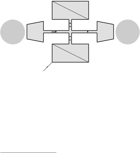
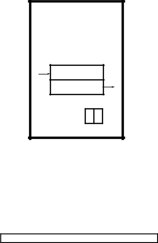
The architecture of the great majority of general-purpose computers and microprocessors is modelled after the von Neumann model shown in
42 The Quintessential PIC Microcontroller
Fig. 3.1.1 The few electronic computers in use up to the late 1940s either only ever ran one program (like the war time code breaking Colossus) or else needed partly rewired to change their behavior (for example the ENIAC). The web site entry for this chapter gives historical and technical details of these prehistorical machines.
Memory
The Input
outside interface world port
Clock
Data
Program code
|
|
|
Output |
The |
|
|
|
||
Data highway |
|
interface |
outside |
|
|
|
|
port |
world |
|
|
|
|
|
|
|
|
|
|
Processing
unit (ALU)
Control
Central Processing Unit
(CPU)
Fig. 3.1 An elementary von Neumann computer.
Von Neumann’s great leap forward was to recognise that the program could be stored in memory along with any data. The advantage of this approach is flexibility. To alter the program simply load the bit pattern into the appropriate area of memory. In essence, the von Neumann architecture comprises a Central Processing Unit (CPU), a memory and a common connecting highway carrying data back and forth. In practice the CPU must also communicate with the environment outside the computer. For this purpose data to and from suitable interface ports are also funnelled through the data highway.
Looking at these elements in a little more detail.
1Von Neumann was a Hungarian mathematician working for the American Manhattan nuclear weapons program during the 2nd World war. After the war he became a consultant for the Moore School of Electrical Engineering at the University of Pennsylvania’s EDVAC computer project, for which he was to employ his new concept where the program was to be stored in memory along with its data. He published his ideas in 1946 and EDVAC became operational in 1951. Ironically, a somewhat lower key project at Manchester University made use of this approach and the Mark 1 executed its first stored program in June 1948! This was closely followed by Cambridge University’s EDSAC which ran its program in May 1949, almost two years ahead of EDVAC.

3. Stored Program Processing 43
The Central Processing Unit
The CPU consists of the ALU/working register together with the associated control logic. Under the management of the control unit, program instructions are fetched from memory, decoded and executed. Data resulting from, or used by, the program is also accessed from memory. This fetch and execute cycle constitutes the operating rhythm of the computer and continues indefinitely, as long as the system is activated.
Memory
Memory holds the bit patterns which define the program. These sequences of instructions are known as the software. The word is a play on the term hardware; as such patterns do not correspond to any physical rearrangement of the circuitry. Memory holding software should ideally be as fast as the CPU, and normally uses semiconductor technologies, such as that described in the last chapter.2 This memory also holds data being processed by the program.
Program memories appear as an array of cells, each holding a bit pattern. As each cell ultimately feeds the single data highway, a decoding network is necessary to select only one cell at a time for interrogation. The computer must target its intended cell for connection by driving this decoder with the appropriate code or address. Thus if location 602Eh is
6 0 2 E
to be read, then the pattern 0110 0000 0010 1110b must be presented to the decoder. For simplicity, this address highway is not shown in Figs. 3.1 and 3.2.
This addressing technique is known as random access, as it takes the same time to access a cell regardless of where it is situated in memory. Most computers have large backup memories, usually magnetic or optical disk-based or magnetic tape, in which case access does depend on the cell’s physical position. Apart from this sequential access problem, such media are normally too slow to act as the main memory and are used for backup storage of large arrays of data (eg. student exam records) or programs that must be loaded into main memory before execution.
The Interface Ports
To be of any use, a computer must be able to interact with its environment. Although conventionally one thinks of a keyboard and screen, any of a range of physical devices may be read and controlled. Thus the flow of fuel injected into a cylinder together with engine speed may be used to alter the instant of spark ignition in the combustion chamber of a gas/petrol engine.
2This wasn’t always so; the earliest practical large high-speed program memories used miniature ferrite cores (donuts) that could be magnetized in any one of two directions. Core memories were in use from the 1950s to the early 1970s, and program memory is sometimes still referred to as core.
44 The Quintessential PIC Microcontroller
Data Highway
All the elements of the von Neumann computer are wired together with the one common data highway, or bus. With the CPU acting as the master controller, all information flow is back and forward along these shared wires. Although this is e cient, it does mean that only one thing can happen at any time. This phenomena is sometimes known as the von Neumann bottleneck.
Memory
Program code
Clock
Program |
|
highway |
|
||
|
Control
Processing
unit (ALU)
The Input
outside interface world port
Data highway
Output The
interface outside port world
Data
Memory
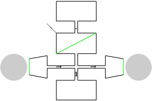
Fig. 3.2 An elementary Harvard architecture computer.
The Harvard architecture illustrated in Fig. 3.2 is an adaptation of the standard von Neumann structure, that separates the shared memory into entirely separate Program and Data stores. The diagram shows two physically distinct buses used to carry information to the CPU from these disjoint memories. Each memory has its own Address bus and thus there is no interaction between a Program cell and a Data cell’s address. The two memories are said to lie in separate memory spaces. The Data store is sometimes known as the File store, with each location n being described as File n.
The fetch instruction down – decode it – execute sequence, the so called fetch and execute cycle, is fundamental to the understanding of
3. Stored Program Processing 45
the operation of the computer. To illustrate this operating rhythm we look at a simple program that takes a variable called NUM_1, then adds 65h (101d) to it and finally assigns the resultant value to the variable called NUM_2. In the high-level language C this may be written as:3
NUM_2 = NUM_1 + 101;
Program memory |
Data memory |
(Code store) |
(File store) |
000 001 movf 05,w addlw 65h
0805 3E65
010 011
020 021
030 031
bus address Program
002 003 movwf 06
0086
012 013
022 023
032 033
00F
01F
02F NUM_1 NUM_2
03F
Program |
|
bus |
data |
|
|
|
address |
|
bus |
|
|
|
BASIC |
File |
|
|
00
01
02
03
04
DATA1 05 |
DATA2 06 |
07
File data bus
|
|
|
Central |
Processing Unit (CPU) |
|
|
||
|
PC |
|
addlw 65hIR1 |
|
|
FAR |
|
FDR |
|
001 |
|
3E65 |
|
|
05 |
|
DATA1 |
|
|
|
|
|
|
|
|
|
|
|
|
|
|
|
|
|
|
Program Counter |
Instruction Register 1 |
File Address |
File Data |
|||||
|
|
|
|
|
Register |
Register |
||
Fetch 
 Execute movf 05,wIR2 Unit Unit
0805
Instruction Register 2 |
|
|
|
|
|
|
ALU |
ID |
Control signals |
Pass |
through |
|
|
||
|
to |
Arithmetic Logic |
|
|
internal resources |
|
|
|
Unit |
|
|
|
|
|
|
Instruction Decoder |
|
|
|
|
|
|
W |
|
|
DATA1 |
|
|
|
Working |
|
|
|
Register |
|
Internal data transfer bus
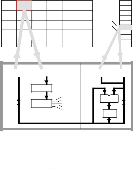
Fig. 3.3 A snapshot of the CPU executing the first instruction whilst fetching down the second instruction.
A rather more detailed close-up of our computer, which I have named BASIC (for Basic All-purpose Stored Instruction Computer) is shown in
3If you are more familiar with PASCAL or Modula-2, then this program statement would be expressed as NUM_2 := NUM_1 + 101
46 The Quintessential PIC Microcontroller
Fig. 3.3. This shows the CPU and memories, together with the two data highways (or buses) and corresponding address buses.
The CPU can broadly be partitioned into two sectors. The leftmost circuitry deals with fetching down the instruction codes and sequentially presenting them to the Instruction decoder. The rightmost sector executes each instruction, as controlled by this Instruction decoder.
Looking first at the fetch process:
Program Counter
Instructions are normally stored sequentially in Program memory, and the PC is the counter register that keeps track of the current instruction word. This up-counter (see Fig. 2.22 on page 37) is sometimes called (perhaps more sensibly) an Instruction Pointer.
As the PC is connected to the Execution unit – via the internal data bus
– the ALU can be used to manipulate this register and disrupt the orderly execution sequence. In this way various Goto and Skip to another part of the program operations can be implemented.
Instruction Register 1
The contents of the Program store cell pointed to by the PC, that is instruction word n, is latched into IR1 and held for processing during the next cycle.
Instruction Register 2
During the same cycle as instruction word n is being fetched, the previously fetched instruction word n − 1 in IR1 is moved into IR2 and feeds the Instruction decoder.
Instruction Decoder
The ID is the ‘brains’ of the CPU, deciphering the instruction word in IR2 and sending out the appropriate sequence of signals to the execution unit as necessary to locate the operand in the Data store (if any) and to configure the ALU to its appropriate mode. In the diagram the instruction shown is movf 5,w (MOVe File 5 to the Working register).
The Execution sector deals with accesses to the Data store and configuring the ALU. Execution circuitry is controlled from the Instruction Decoder, which is in turn commanded by Instruction word n − 1 in IR2.
File Address Register
When the CPU wishes to access a cell (or file) in the Data store, it places the file address in the FAR. This directly addresses the memory via the File address bus. As shown in the diagram, File 5 is being read from the Data store and the resulting datum is latched into the CPU’s File Data Register.
File Data Register
This is a bi-directional register which either:
3. Stored Program Processing 47
• Holds the contents of an addressed file if the CPU is executing a Read cycle. This is the case for instruction 1 (movf 5,w) that moves (reads) a datum from File 5 into the Working register.
•Holds the datum that a CPU wishes to send out (Write) to an addressed file. This Write cycle is implemented for instruction 3 (movwf 6) that moves (writes) out the contents of the Working register to File 6.
Arithmetic Logic Unit
The ALU carries out an arithmetic or logic operation as commanded by its function code (see Fig. 2.9 on page 25) as generated by the Instruction Decoder.
Working Register
W is the ALU’s working register, generally holding one of an instruction’s operands, either source or destination. For example, subwf 20,w subtracts the contents of the Working register from the contents of File 20 and places the di erence back in W. Some computers call this a Data register or Accumulator register.
In our BASIC computer, each instruction word in the Program store is 14 bits long. Some of these bits code the operation, for example 000111b for Add and 000110b for Exclusive-OR. This portion of the Instruction word is called the operation code or op-code (see Chapter 5). The rest of the instruction word bits generally relate to where in the Data store the operand is or sometimes a literal (constant) operand, such as in addlw 6 (ADD Literal 6 to W). For example the instruction word for SUBtract File from W (subfw) is structured as op-code d f, where:
•The op-code for Subtract is 000010b or 02h.
•d is the destination for the di erence, with 0 for W and 1 for a file, as specified below.
•f is the 7-bit address of the subtrahend file (and destination if d is 1), from 00h through to 7Fh.
For example subwf 20h,w is coded as 000010  0
0  0100000 b or 0220h. As the Program and Data stores are separate entities, their cell size need not be the same. In our case each file holds an 8-bit byte datum. In consequence both the ALU and Working register are also byte sized. Generally the ALU size defines the size of the computer, and so BASIC could be described as an 8-bit machine. Real computers range in size from one bit up to 64 bits. From the previous example we see that seven bits of the instruction code are reserved for the file address, and thus the Data store has a maximum capacity for direct access limited to 128 (27)
8-bit files.
The Program memory capacity is a function of the Program Counter. If this were 10 bits wide, then the Program store could directly hold 1024 (210) 14-bit instructions. OK. We have got our CPU with its Program and Data stores. Let us look at the program itself. There are three instructions

48 The Quintessential PIC Microcontroller
in our illustrative software, and as we have already observed the task is to copy the value of a byte-sized variable NUM_1 plus 101d (65h) into a variable called NUM_2. This is symbolized as:
NUM_2 = NUM_1 + 101;
We see from our diagram that the variable named NUM_1 is simply a symbolic representation for “the contents of File 5” (which is shown as DATA1), and similarly NUM_2 is a much prettier way of saying “the contents of
File 6” (shown as DATA2).
Now as far as the computer is concerned, starting at location 000h our program is:
00100000000101
11111001100101
00000010000110
Unless you are a CPU this is not much fun!4
Using hexadecimal5 is a little better.
0805
3E65
0086
but is still instantly forgettable. Furthermore, the CPU still only understands binary, so you are likely to have to use a translator program running on, say a PC, to translate from hexadecimal to binary.
If you are going to use a computer as an aid to translate your program, known as source code, to binary machine code, known as object code, then it makes sense to go the whole hog and express the program symbolically. Here the various instructions are represented by mnemonics (eg. clrf for CLeaR File, subwf for SUBtract File from W) and variables’ addresses are given names. Doing this our program becomes:
movf |
NUM_1,w |
; Copy the variable NUM_1 to W |
|
|
addlw |
101 |
; |
Add the literal constant 101 |
decimal to it |
movwf |
NUM_2 |
; |
Copy NUM_1+101 into NUM_2 |
|
|
|
|
|
|
where the text after a semicolon is comment, which makes the program
easier to understand by the tame human programmer.
Chapter 8 is completely devoted to the process of translation from this assembly-level source code to machine-readable binary. Here it is only necessary to look at the general symbolic form of an instruction, which is:
instruction mnemonic <operand A>,<operand B>
4I know; I have programmed this way back in the primitive middle 1970s.
5Remember that we are only using hexadecimal notation as a human convenience. If you took an electron microscope and looked inside these cells you would only ‘see’ the binary patterns indicated.
3. Stored Program Processing 49
A few instructions have no explicit operand, such as return (RETURN from subroutine) and nop (No OPeration); however, the majority have one, two or even three operands. For instance, the operation Clear on its own does not make sense. Clear what? Thus we need to say “clear the destination file”; for example clrf 20h to clear File 20h. Here Operand A is the file address 20h. This could be written as (f) <- 00, where the brackets mean “contents of” and <- means “becomes”. This notation is called register transfer language (rtl).
Many instructions have two operands. Thus the instruction incf f,d takes a copy of the contents of the specified file plus one and places this in either the Working register (d = w) or back in the file itself (d = f). For example, incf 20h,w means “deposit the contents of File 20h plus one in the Working register”. In rtl this is W <- (f20) + 1.
Three-operand instructions are common. For example, addwf f,d adds the W register’s contents to the specified file’s contents and deposits the result either in W or in the file itself. Thus addwf 20h,f means “add the contents of W to that of File 20h and put the outcome in File 20h” or (f20) <- W + (f20). Of course this is not a true 3-operand instruction as the destination must be one of the two source locations; that is W or File 20h. It is more accurately described as a 212 -operand instruction!
All three instructions in our exemplar program have two operands, of which the Working register is either the source or/and destination. Where an instruction has a choice of destination d – as in movf f,d – then this is indicated appropriately as Operand B. Thus in our program movf 5,w. Where the source or destination is fixed as the Working register then this is indicated in the mnemonic itself, as in addlw (ADD Literal to W) and movwf (MOVe W to File).
The first and last instructions specify an absolute file, which is an actual location in the Data store. In a large program it is easier for us humans to give these variables symbolic names, such as NUM_1 for File 5 and NUM_2 for File 6. Of course we must somewhere tell the assembler (the program that does the translation) that NUM_1 and NUM_2 equate to addresses File 5 and File 6 respectively.
The middle instruction addlw 101 adds a constant number or literal (that is 101d or 65h) to W rather than a variable in memory. This literal is actually stored as part of the instruction word bit pattern (see page 107). In rtl this instruction implements the function W <- W + 65. In some cases it may be desirable to give a literal a symbolic name.
In writing programs using assembly-level symbolic representation, it is important to remember that each instruction has a one to one correspondence to the underlying machine instructions and its binary code. In Chapter 9 we will see that high-level languages loose that 1:1 relationship.
The essence of computer operation is the rhythm of the fetch and execute cycles. Here each instruction is successively brought down from

50 The Quintessential PIC Microcontroller
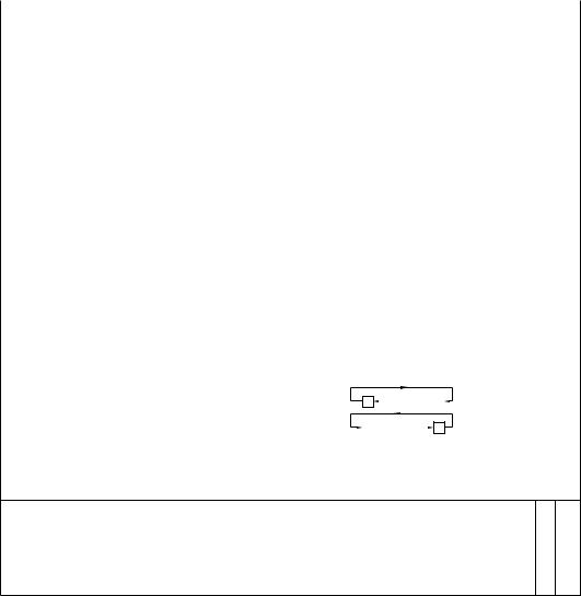
the Program store (fetched), interpreted and then executed. As any execution memory access will be on the Data store and as each store has its own busses, then the fetch and execution processes can progress in parallel. Thus while instruction n is being fetched, instruction n−1 is being executed. In Fig. 3.3 the instruction codes for both the imminent and current instructions are held in the two Instruction registers IR1 and IR2 respectively. This structure is known as a pipeline, with instructions being fetched into one end and ‘popping out’ into the Instruction decoder at the other end. Figure 3.4 below shows the time line of our 3-instruction exemplar program, quantized in clock cycles. During each clock cycle, except for the first, both a fetch and an execution is proceeding simultaneously.
|
|
Cycle 1 |
|
|
Cycle 2 |
Cycle 3 |
|
|
Cycle 4 |
|||
|
|
|
|
|
|
|
|
|
|
|
|
|
Fetch stream , IR1 |
|
Fetch movf 5,w |
|
|
Fetch addlw 65h |
|
|
Fetch movwf 6 |
|
|
Fetch next instr |
|
|
|
|
|
|
|
|
|
|
|
|
|
|
Execute stream, IR2
|
Execute movf 5,w |
|
|
Execute addlw 65h |
|
|
Execute movwf 6 |
|
|
|
|
|
|
|
|
|
|
 Time
Time
Fig. 3.4 Parallel fetch and execute streams.
In order to illustrate the sequence in a little more detail, let us trace through our specimen program. We assume that our computer (that is the Program Counter) has been reset to 000h and has just finished the Cycle 1 fetch.
Fetch (Fig. 3.3) . . . . . . . . . . . . . . . . . . . . . . . . . . . . . . . . . . . . . . . . . . . . . . . . . . . . . . Cycle 2
•Increment the Program Counter to point to instruction 2.
•Simultaneously move the instruction word 1 down the pipeline (from Instruction register 1 to Instruction register 2).
•Program Counter (001h) to Program address bus.
•The instruction word 2 then appears on the Program data bus and is loaded into Instruction register 1.
Execute (Fig. 3.3) . . . . . . . . . . . . . . . . . . . . . . . . . . . . . . . . . . . . . . . . . . . . . . . . . . . .Cycle 2
•The operand address 05h (i.e. NUM_1) to the File Address register and out onto the File address bus.
•The resulting datum at NUM_1 is read onto the File data bus and loaded into the File Data register.

3. Stored Program Processing 51
•The ALU is configured to the Pass Through mode, which feeds the datum through to the Working register.
Fetch . . . . . . . . . . . . . . . . . . . . . . . . . . . . . . . . . . . . . . . . . . . . . . . . . . . . . . . . . . . . . . . . Cycle 3
•Increment the Program Counter to point to instruction 3.
•Simultaneously move the instruction word 2 down the pipeline (from Instruction register 1 to Instruction register 2).
•Program Counter (002h) to Program address bus.
•The instruction word 3 then appears on the Program data bus and is loaded into the pipeline at Instruction register 1.
Execute . . . . . . . . . . . . . . . . . . . . . . . . . . . . . . . . . . . . . . . . . . . . . . . . . . . . . . . . . . . . . .Cycle 3
•The ALU is configured to the Add mode and the literal (which is part of instruction word 2) is added to the datum in W.
•The ALU output, NUM_1 + 65h, is placed in W.
Fetch . . . . . . . . . . . . . . . . . . . . . . . . . . . . . . . . . . . . . . . . . . . . . . . . . . . . . . . . . . . . . . . . Cycle 4
•Increment the Program Counter to point to instruction 4.
•Simultaneously move instruction word 3 down the pipeline to IR2.
•Program Counter (003h) to Program address bus.
•The instruction word 4 then appears on the Program data bus and is loaded into the pipeline at IR1.
Execute . . . . . . . . . . . . . . . . . . . . . . . . . . . . . . . . . . . . . . . . . . . . . . . . . . . . . . . . . . . . . .Cycle 4
•The operand address (i.e. NUM_2) 06h to the File Address register and out onto the File address bus.
•The ALU is configured to the Pass Through mode, which feeds the contents of W through to the File Data register and onto the File data bus.
•The datum in the File Data register is written into the Data store at the address on the File address bus and becomes the new datum in NUM_2.
Notice how the Program Counter is automatically advanced during each fetch cycle. This sequential advance will continue indefinitely unless an instruction to modify the PC occurs, such as goto 200h. This would place the address 200h into the PC, overwriting the normal incrementing process, and e ectively causing the CPU to jump to whatever instruction was located at 200h. Thereafter, the linear progression would continue.
Although our program doesn’t do very much, it only takes around 1 µs to implement each instruction. A million unimpressive operations each second can amount to a great deal! Nevertheless, it hardly rates highly in

52 The Quintessential PIC Microcontroller
the annals of software, so we will wrap up our introduction to computing by looking at some slightly more sophisticated examples.
Writing a program is somewhat akin to building a house. Given a known range of building materials, the builder simply puts these together in the right order. Of course there are tremendous skills in all this; poor building techniques lead to houses that leak, are drafty and eventually may fall down!
It is possible to design a house at the same time as it is being built. Whilst this may be quite feasible for a log cabin, it is likely that the final result will not remain rain proof very long, nor will it be economical, maintainable, ergonomic or very pretty. It is rather better to employ an architect to design the edifice before building commences. Such a design is at an abstract level, although it is better if the designer is aware of the technical and economic properties of the available building materials.
Unfortunately much programming is of the ‘on the hoof’ variety, with little thought of any higher-level design. In the software arena this means devising strategies and designing data structures in memory. Again, it is better if the design algorithms keep in mind the materials of which the program will be built; in our case the machine instructions.
At the level of our examples in this chapter, it will be this coding (building) task we will be mostly concerned with. Later chapters will cover more advanced structures which will help this process, and we will get more practice at devising strategies and data structures.
In order to code software we must have a knowledge of the register architecture of the computer/microcontroller and of the individual instructions. Figure 3.5 shows the programming model we will use for our exercises. This shows all registers that can be ‘got at’ by the programmer.
I have added three registers to the previous complement that actually are part of the Data store rather than the CPU but have a special significance for the programmer. File 0 and File 4 are a pair of Address registers working in tandem to point to an object in memory, as described further on in Fig. 3.6. The Status Register6 STATUS comprises two bits in File 3 that are used to tell the software something about the outcome from an instruction. Thus the C flag (bit 0 in File 3) primarily holds the Carry out from the last Addition operation. For instance (in decimal) 5 + 2 = 7C0; 5 +9 = 4C1. It also functions as the complement of the Borrow out from a Subtraction operation. For example 5 − 2 = 3B1; 5 − 9 = 6B0. The Z flag (bit 2 in File 3) is set if the result of the last operation is zero.
Table 3.1 shows all the instructions supported by the BASIC computer. Before looking at these, let us discuss the concept of the address mode. Most instructions act on data, which may be in internal CPU registers or out in the Data store. Thus the location of such operands must be part of the instruction. It isn’t su cient to simply state clr – Clear what? There
6Some processors use the term Code Condition register.
3. Stored Program Processing 53
Table 3.1: Our BASIC computer’s instruction set.
Instruction |
Mnemonic |
|
|
Operation |
Flags |
||||||||
|
|
|
|
|
|
|
|
|
|
|
|
|
|
|
|
|
|
|
|
|
|
|
|
|
|
Z |
C |
|
|
|
|
|
|
|
|
|
|
|
|
|
|
|
|
|
|
|
|
|
|
|
|
|
|
|
|
Arithmetic |
|
|
|
|
|
|
|
|
|
|
|
|
|
|
|
|
|
|
|
|
|
|
|
|
|
||
Add W and F |
addwf |
f,d |
(d) <- W + (f) |
√ |
√ |
||||||||
Add Literal and W |
addlw |
L |
W <- #L + W |
√ |
√ |
||||||||
Clear F |
clrf |
f |
(f) <- 00 |
|
|
|
|
√ |
• |
||||
Clear W |
clrw |
f,d |
(f) <- 00 |
|
|
|
|
√ |
|||||
Increment F |
incf |
(d) <- (f) + 1 |
√ |
• |
|||||||||
Decrement F |
|
|
|
|
|
|
|
|
|
|
|
√ |
• |
decf |
f |
(d) <- (f) - 1 |
• |
||||||||||
Subtract W from F |
subwf |
f,d |
(d) <- (f) - W |
√ |
√ |
||||||||
Subtract W from L |
sublw |
L |
W <- #L - W |
√ |
√ |
||||||||
Movement |
|
|
|
|
|
|
|
|
|
|
|
|
|
|
|
|
|
|
|
|
|
|
|
|
|
|
|
Move F |
movf |
f,d |
(d) <- (f) |
√ |
• |
||||||||
Move W to F |
movwf |
f |
W <- (f) |
|
|
|
|
|
|
• |
• |
||
Move Literal to W |
movlw |
L |
W <- #L |
|
|
|
|
|
|
• |
• |
||
Logic |
|
|
|
|
|
|
|
|
|
|
|
|
|
|
|
|
|
|
|
|
|
|
|
|
|
|
|
AND W and F |
andwf |
f,d |
(d) <- W |
|
|
(f) |
√ |
• |
|||||
AND Literal and W |
andlw |
L |
W <- #L |
· |
·W |
√ |
|||||||
Complement F |
|
|
|
|
|
|
|
|
|
√ |
• |
||
comf |
f |
(f) <- (f) |
• |
||||||||||
Inclusive OR W and F |
iorwf |
f,d |
(d) <- W + (f) |
√ |
|||||||||
Inclusive OR Literal and W |
|
|
|
|
|
|
|
|
|
|
|
√ |
• |
iorlw |
L |
W <- #L + W |
• |
||||||||||
Rotate left F |
rlf |
f,d |
(d) <- |
C |
|
|
|
|
|
|
|
• |
√ |
|
|
|
f |
|
|||||||||
Rotate right F |
rlr |
f,d |
(d) <- |
|
|
|
|
|
C |
• |
√ |
||
|
|
f |
|
|
|||||||||
eXclusive OR W and F |
xorwf |
f,d |
(d) <- W |
|
|
|
(f) |
√ |
• |
||||
eXclusive OR Literal and W |
xorlw |
L |
W <- #L |
|
√ |
||||||||
|
|
W |
• |
||||||||||
Skip and Jump
Bit Test F, Skip if Clear |
btfsc |
f,b |
b |
== |
0 ? |
|
PC++ : |
PC |
||
Bit Test F, Skip if Set |
btfss |
f,b |
b |
== |
1 ? |
|
PC++ : |
PC |
||
Decrement F, Skip if Zero |
decfsz |
f |
--(f) == |
0 ? |
PC++ : |
|||||
Go to address |
goto |
<ea> |
PC <- |
<ea> |
|
|
|
|||
Increment F, Skip if Zero |
incfsz |
f |
++(f) |
== |
0 |
? |
PC++ : |
|||
|
|
|
|
|
|
|
|
|
|
|
• •
• •
PC √ •
• •
PC √ •
√ |
: Flag operates normally |
• |
: Flag not a ected |
||
<ea> |
: E ective address |
b |
: Bit b (0–7) in file |
||
C |
: Carry or |
|
bit 0 in F3 |
Z |
: Zero, bit 2 in F3 |
Borrow, |
|||||
d |
: Destination; 0 = W, 1 = file |
W |
: Working register |
||
L |
: 8-bit Literal |
== |
: Equivalent to |
||
++ |
: Increment |
-- : Decrement |
|||
A?S1:S2 |
: IF A is True THEN DO S1 ELSE DO S2 |
|
|
||
54 The Quintessential PIC Microcontroller
7 |
0 |
|||
|
|
Working |
register |
|
|
|
|
|
|
9 |
|
|
0 |
|
|
|
|
F2 |
|
|
|
Program Counter |
|
|
|
|
|
|
|
7 |
0 |
|||
F0
Indirect Pointer register
F4
File Select register
Address register pair
2 0
Z C
Status register (F3)
Fig. 3.5 Programmer’s model.
are di erent ways of specifying the operand location. These are known as address modes.
Inherent
A few instructions, not shown in Table 3.1, do not explicitly refer to any location. For example return for RETURN from subroutine..
Register Direct
Here the operand is specified to be in the Working register. For example:
clrw |
; Clear the Working register |
|
|
Most instructions specify at least one operand should be in W. In many cases W can be both a source and the destination operand. For instance:
addwf f,w ; Add W to a file and put the answer in W
where W initially holds one of the two source datum bytes, and ends up holding the outcome datum.

3. Stored Program Processing 55
Literal
This address mode is used to specify an operand which is constant data rather than a location. For example:
addlw 120 ; Add the constant 120 (#120) decimal to W
Only special literal instructions are used with this type of data, such as movlw and sublw. The destination of this type of instruction is always W. The sublw instruction sometimes causes confusion as it actually takes away the contents of W from the literal byte and not vice versa. Thus sublw 1 does not subtract one from the contents of W (i.e. decrement W) but 1 − W. To decrement the contents of W use addlw -1 (i.e. addlw 0FFh). Note the use of the # symbol in the rtl description to denote that the following number is constant data.
A few instructions can test or modify a single bit in a File. For instance:
btfsc 3Fh,6 ; Test File 3Fh bit 6; skip next instr. IF Clear
in which Operand B is the fixed literal 6, specifying the bit position in Operand A’s specified File.
In both kinds of literal instruction the constant is encoded as part of the instruction word. In the former, eight bits of the 14-bit word is used, and in the latter three bits (see Appendix A).
File Direct
Here the totally fixed file address of the operand, either source or/and destination is directly specified. For example:
clrf 20h ; Clear the byte at File store address 20h
clears the byte out at File 20h.
In many cases the same file can be both source and destination. Thus:
incf 20h,f ; Put the contents of File 20h plus 1 into File 20h
as opposed to the Working register:
incf 20h,w ; Put the contents of File 20h plus one into W
which uses File Direct addressing for Operand A and Register Direct for Operand B.
The main characteristic of this address mode is that the location of the operand is fixed as an integral part of the program, and thus cannot be changed as execution progresses. Although directly specifying its address may seem to be the obvious way to locate an object in the Data store, in some situations this technique is rather inflexible.
Suppose we wished to clear all file registers from 0Ch through to 3Fh in the File store, say to hold an array of 52 byte elements. The obvious

56 The Quintessential PIC Microcontroller
Program 3.1 Clearing a block of files the linear way.
CLEAR_ARRAY |
clrf |
0Ch ; Clear File 12 |
|
|
clrf |
0Dh ; and File 13 |
|
|
clrf |
0Eh ; Each clrf |
|
|
clrf |
0Fh ; uses one instruction word |
|
|
clrf |
10h |
; in the Program store |
|
clrf |
11h |
; File 17 cleared |
|
clrf |
12h |
; and so on |
|
.... ... |
|
|
|
.... ... |
|
|
|
clrf |
3Eh ; Clear File 62; nearly there |
|
|
clrf |
3Fh ; Clear File 63; Phew! |
|
|
|
|
|
way to do this is shown in Program 3.1, which uses a clrf instruction for each byte. Although it works, it is rather ine cient, and the mind boggles if you wanted to clear, say, a 1 Kbyte File store. There has got to be a better way!
File Indirect
Indirect addressing uses an address register to hold the address of an operand. This address register thus acts as a pointer into the Program store. The term indirect is used as this address register does not hold the operand datum itself, only a pointer address to it. The advantage of this seemingly perverse way of accessing data in the Data store, is that the e ective address (ea) is a variable and this can be altered by the program as it progresses. This ea is the contents of this special pointer address register.
In our BASIC computer the File Select Register (FSR) is implemented as File 4 in the File store. The indirect mechanism is evoked when the dummy address File 0 (there is no physical file at location 0 in the Data store) is used for the operand address, as shown in Fig. 3.6.7 Thus, for example, if the contents of File 4 happened to be 20h then:
movwf 0 ; Store datum in W out to place pointed to by File 4
will e ectively copy the contents of W out to File 20h.
This seems rather an obscure way of doing things, but by way of a justification let us revisit our array clearing example of Program 3.1. Repeating the same thing 52 times on successive file locations is a dubious way of doing this. Why not use a pointer into the array, and increment this pointer each time we do a Clear? That is, rather than using a constant address for the destination operand use a variable e ective address.
Program 3.2 follows the scheme by folding the linear structure of the previous program into a loop, shown shaded. The execution path keeps
7Although this all seems rather complicated, I have kept in mind the microcontroller that we will be examining in the following chapters.
referencing Instruction
|
|
|
|
3. Stored Program Processing 57 |
|||||||||
|
|
|
|
|
|
|
|
|
|
|
|
File |
store |
|
|
|
|
|
|
|
|
|
|
|
the |
|
|
|
|
|
|
|
|
|
|
|
|
to |
|
|
|
|
|
|
|
|
|
|
|
|
out |
|
|
|
|
|
|
|
actually |
|
|
|
|
|
|
|
|
|
|
|
F0 |
|
|
|
|
F4 |
|
|
|
|
|
||
|
|
|
|
|
|
this |
address |
|
|
|
|
|
|
|
|
|
sends |
|
|
|
|
|
|
|
|
|
|
|
|
|
|
|
|
|
|
|
|
|
|
|
|
Fig. 3.6 The indirect mechanism.
circulating around the clrf instruction, which is ‘walked’ through the array of files by advancing the pointer in File 4, the FSR, on each pass through the loop. Eventually the pointer moves beyond the desired range and the program then exits the loop and continues onto the next section of code.
Program 3.2 has many new features, especially as we haven’t yet reviewed the instruction set.
Program 3.2 Clearing a block of files using a repeating loop.
; Name |
the |
various |
registers & bits for |
readibility |
|||
FSR |
equ |
4 |
; Give |
File |
4 |
the name FSR (File Select Reg.) |
|
SR |
equ |
3 |
; Give |
File |
3 |
the name SR (Status Register) |
|
Z |
equ |
2 |
; The Z flag is bit 2 of the |
SR |
|||
Go here if FSR
; Now for |
the program |
proper |
CLEAR_ARRAY |
movlw 0Ch |
; Put start address in W |
30h |
movwf FSR |
; and into the FSR as a pointer |
|
|
to |
|
CLOOP |
|
|
|||
equal |
|
; Now |
|
|
|
||
not |
|
|
|
is |
|
|
|
|
|
clrf |
0 |
; |
Clear byte pointed to by |
FSR |
||
|
|
incf |
FSR,f |
; |
Increment pointer in FSR |
|
||
check, is |
pointer |
at top |
yet? |
|
|
|||
|
|
movf |
FSR,w |
; |
Copy the pointer |
address |
into W |
|
|
|
sublw |
40h |
; |
Compare |
with the |
end address (40h) |
|
|
|
btfss |
SR,Z |
; |
IF Zero |
flag in SR is set THEN fini |
||
|
|
|||||||
|
|
goto |
CLOOP |
; |
ELSE do |
the next |
pass thru the loop |
|
|
.... |
.... |
; |
Next part of the |
program |
|
||

58 The Quintessential PIC Microcontroller
Phase 1
From the point of view of readability, variables, registers and individual status and control bits should be given a relevant name. For example, btfss STATUS,Z (Bit Test File Skip if Set) which checks the Z flag (bit 2 in File 3) and skips the following instruction if set (that is the outcome of the previous instruction is zero) can be written in two ways; both of which are functionally identical:
btfss 3,2 ; IF bit 2 of File 3 is set THEN finished btfss STATUS,Z ; IF Zero flag in STATUS is set THEN finished
Obviously the latter is preferable. Although this might seem to be a cosmetic exercise, clarity reduces the chance of error and makes debugging and subsequent alteration easier. Realistic programs, rather than the code fragment illustrated here, use many variables and register bits, so lucidity is all the more important.
The three header lines of our program illustrate the means whereby the programmer tells the assembler translator program to substitute numbers for names. For example the line:
FSR equ 4
states that when the programmer uses the name FSR as an operand, it is to be substituted by the number 4 (that is File 4). The equ directive means “equivalent to”. A directive is a pseudo instruction in that it does not usually produce actual machine code but rather is a means of passing information from the programmer to the assembler program.
Phase 2
The first two proper instructions initialize the File Select Register to point to the first byte to be cleared, by moving the constant 0Ch into the Working register and then out to File 4. Nearly all loop instructions involve some setting up before entry.
Phase 3
The key Clear instruction uses the File Indirect address mode by specifying the phantom File 0 as the destination address. This line has a label associated with it called CLOOP. The assembler knows that this is a label and not an instruction as it appears in the leftmost column of the source file. Lines without labels should begin with an indent of at least one space.
Each pass around the loop involves an incrementation of the pointer. This is done by using the incf FSR,f instruction to increment the FSR file. Notice that the destination here is specified as a file and not the W register.
Phase 4
Unless you wish to go round the loop forever, we need a mechanism to eventually exit. In our case this is done by comparing the contents of the
3. Stored Program Processing 59
FSR pointer file with the constant 40h, that is with one over the top target file 3Fh. The comparison mechanism is to copy the contents of the FSR pointer into W and then subtract W from the literal 40h using sublw 40h. If they are equal then the Z flag will be set and in this event the next btfss instruction will skip over the following goto LOOP instruction, out of the loop. Until this happens, the goto instruction will move the execution back up to the beginning of the loop and the process is repeated with the FSR advanced to point to the next file to be cleared.
All together our loop version takes eight machine instructions against the 52 of the linear equivalent. However, it does take longer to execute as the six instructions in the loop are repeated 52 times!
Absolute
The goto instruction forces the execution to directly transfer to the specified address by simply overwriting the Program Counter with the e ective address – for example goto 145h puts 145h into the PC. It contrasts with the various Skip instructions (see page 61) which simply branch over the following instruction, wherever they are encountered. This latter type of branch is called relative, as opposed to the absolute transfer of execution used by the goto instruction.
Having covered the address modes, let us look briefly at the instruction set in Table 3.1. Instructions have been divided into four groups as follows.
Arithmetic
This covers the Addition, Subtraction, Incrementation, Decrementation and Clearing operations. Addition is possible between data in W and out in the File store, with the sum being placed either in the same file or in W. Similarly subtraction of W from a file is implemented, with the di erence being placed in the same file or W. Both instructions come in a literal version, where W is added to/subtracted from an 8-bit constant, with the outcome remaining in the Working register. Notice that in the latter case the variable in W is subtracted from the literal rather than the more obvious subtraction of the literal from W.
The contents of any file can be incremented or decremented using incf and decf respectively. The outcome is usually put back into the file but the Working register can alternatively be specified as the destination.
Any file can be cleared with clrf, for instance clrf 20h. In the same manner the Working register can be zeroed with clrw.
Movement
This category of instructions copy a datum from source to destination. In all cases the contents of the source remains unaltered. movf reads (loads) a byte from the File store, usually into the Working register; eg. movf 20h,w. It is possible to specify the seemingly useless operation of copying a file’s datum on top of itself, such as in move 20h,f. However,
60 The Quintessential PIC Microcontroller
this does have the side e ect of setting the Z flag if the datum is zero but in any case not altering a file’s contents. This can be used to implement a Test for Zero operation.
Other instructions in this category write (store) the contents of W out into the File store (eg. movwf 20h copies W into File 20h) or a literal into W (eg. movlw 6 puts the constant 06h into W).
Logic
The comf instruction inverts (complements or NOTs) all bits in the specified file (see Fig. 1.1 on page 12). For example:
10001110 |
|
|
comf 20h |
01110001 |
|
|
||
|
|
|
||||||
|
|
|
F 20h |
|
|
|
|
F 20h |
|
|
|
|
|
|
|||
|
|
|
|
|
||||
The andwf instruction bitwize ANDs (see Fig. 1.2 on page 13) the contents of the Working register to that of a specified file, with the outcome being either in W or in the file. For example:
00001111 |
|
|
andwf 20h,f |
10010111 |
|
|
00000111 |
|
|
|||
|
|
|
|
|
||||||||
|
|
|
W |
|
|
|
|
F 20h |
|
|
|
F 20h |
|
|
|
|
|
|
|
|
|
||||
|
|
|
|
|
|
|
||||||
It is also possible to AND a constant to W by using the andlw variant. Whilst the AND operation can be used to zero (mask) any bit or bits in
the specified file, the Inclusive-OR equivalent instructions can set to one any bit or bits in the destination. For example, ORing W with the literal
10000000b (80h):
00001110 |
|
|
iorlw 80h |
10001110 |
|
|
||
|
|
|
||||||
|
|
|
W |
|
|
|
|
W |
|
|
|
|
|
|
|||
|
|
|
|
|
||||
remembering from Fig. 1.3 on page 13 that ORing with a logic 1 always results in a logic 1 outcome and ORing with zero does not alter the original data, leads to the outcome that the most significant bit position of W is set and the other bits remain unaltered.
The xorwf and xorlw instructions provide for the eXclusive-OR operation. You will recall from page 14 that XORing with a 0 leaves a data bit unchanged, whilst XORing with a 1 inverts (or toggles) that bit. Thus, for example if we wished to invert both bits 0 and 7 of W:
10001110 |
|
|
xorlw 81h |
00001111 |
|
|
||
|
|
|
||||||
|
|
|
W |
|
|
|
|
W |
|
|
|
|
|
|
|||
|
|
|
|
|
||||
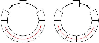
Two instructions are provided that can shift the contents of any file once left or right, with the outcome either remaining in the file or appearing in the W register. As shown in Fig. 3.7 the outgoing bit (bit 7 for rlf f,d and bit 0 for rrf f,d) is placed in the C flag, whilst the incoming bit at the opposite end is the previous value of C. Because of this ‘circular’ action these instructions are said to implement a Rotate data through the Carry operation.
3. Stored Program Processing 61
7 Bit
Bit 0, File 3
C 
rrf
Bit
0
7 Bit
Bit 0, File 3
 C
C
rlf
Bit
0
(a) Rotate Right File |
(b) Rotate Left File |
Fig. 3.7 Circular shifts.
Skip and Jump
These instructions alter the state of the Program Counter, e ectively interrupting the progressive flow of the program and causing processing to branch to another point in the code. The simplest of these instructions is goto. This overwrites the PC with the absolute destination address. For instance, goto 200h will change the PC to 200h and cause the program flow to ‘jump’ to whatever instruction is located at this address. Another example is instruction 8 in Program 3.2 where execution jumps back up to the beginning of the loop at address CLOOP.
The goto instruction causes an unconditional absolute jump in the program flow, implementing a ‘Jump Always’ operation. The remaining four instructions are conditional in that the smooth program progression is interrupted only if the outcome matches the specified state. For instance decfsz decrements the specified file contents and if and only if the outcome is zero the following instruction is skipped over.
Four instructions in our set come into this category, in that they increment the PC if some condition is fulfilled. Remembering that each instruction occupies one word in Program memory, incrementing the PC is equivalent to skipping over the following instruction. This relative skipover action is in contrast with the absolute always jump to the specified address action of the goto instruction.
The four relative instructions are:
btfsc
Bit Test File & Skip if Clear by-passes the next instruction if the specified bit in the file in question is zero. For example btfsc 3,02h skips if bit 2 in File 3 is clear.
btfss
Bit Test File & Skip if Set by-passes the next instruction if the specified bit in the file in question is one. For example btfss 3,02h skips if bit 2 in File 3 is one.

62 The Quintessential PIC Microcontroller
decfsz
DECrement File & Skip if outcome is Zero subtracts one from the specified file and by-passes the next instruction if the outcome is zero. For example decfsz 30h,f skips if the content of 30h once decremented is zero. The decremented value is placed back in the file in this example but W is an alternative destination, as in decfsz 30h,w.
incfsz
INCrement File & Skip if outcome is Zero adds one to the specified file and by-passes the next instruction if the outcome is zero. For example incfsz 30h,f skips if the content of 30h once incremented is zero. The incremented value is placed back in the file in this example but W is an alternative destination, as in incfsz 30h,w.
Actually the Program Counter is located in the Data store as File 2. Thus manipulating this file can implement a computed relative skip. For example:
movf |
2,w |
; Bring the current value of the PC into W |
addlw |
6 |
; Add six to it |
movwf |
2 |
; Update PC, that is hop forward six places |
|
|
|
More details of this technique are given on page 86.
As more sophisticated example of the use of conditional Skip instructions and the absolute goto instructions, consider the problem of repeating a sequence 16 times. The most e cient approach to the coding is to construct a program loop and keep track of the number of times the processor executes the encapsulated instructions. In the following listing File 22h is used as the counter, initialised to 16 before the loop is entered. At the end of the sequence the count is decremented using decfsz and normally the next instruction, which transfers the PC back up to the start of the loop, is executed. However, eventually the count reaches zero and the goto LOOP instruction is skipped over, with execution consequently exiting the loop. Traditionally the potentially skipped over instruction is shown indented as a matter of style.
movlw 16 ; Set up constant #16
movwf 22h ; and put in File 22h for use as a counter
;Now for the sequence of instructions to be repeated 16 times LOOP ..... ... ; DO this
..... ... ; DO that
..... ... ; DO the other
;Count mechanism
decfsz |
22h |
; |
Decrement count. |
IF zero THEN exit loop -- |
goto |
LOOP |
; |
ELSE repeat loop |
| |
|
|
|
|
| |
..... ... |
|
|
<-- |
|

3. Stored Program Processing 63
The incfsz instruction works in a similar manner, but for an up count, skipping when the target file overflows FF → 00h. As an exercise, repeat the example but using incfsz in place of decfsz.The ++(f) and --(f) rtl symbology used to describe the incfsz and decfsz instructions indicate that the contents of the designated file is augmented or decremented before testing for zero.
The other set of skip instructions uses the state of any bit b in any file to force a conditional skip. Thus if it is desired that the program transfers to an instruction located at label REAL_TIME if bit 2 of File 0Bh is logic 1, then we can use the btfsc (Bit Test File & Skip on Clear) instruction thus:
btfsc 0Bh,2 ; Bit Test File 0Bh bit 2. IF==0 THEN skip goto REAL_TIME ; ELSE == 1, GOTO REAL_TIME
In Table 3.1 the rtl language description of this instruction is given as b==0?PC++:PC, which can be read as:
1.Is the specified bit (b) equivalent to (==) zero (?).
2.If true then increment the PC (PC++), that is skip.
3.Else it is false, so leave the PC alone.
Similarly the -- rtl operator is used to indicate decrementation.
Examples
Example 3.1
Write a program to add the byte contents in File memory called NUM1 (File 20h) to NUM2 (File 21h). The outcome is to be in SUM_H and SUM_L (File 22h and File 23h respectively) in the order high:low byte.
Solution
This is similar to our load-add-store program on page 48 but the second operand is a byte variable in memory rather than a constant. The three instructions to implement this are shown in Program 3.3. The variable NUM1 is simply fetched down into the Working register and then added to variable NUM2. The outcome of this is then copied into the sum byte
SUM_L.
Of course this will only work if the outcome of the addition can fit into a single byte; that is no more than FFh (255d). If, for example, both NUM1 and NUM2 were FFh, then the outcome would be 1 FFh. Thus we need to reserve two bytes for the sum; an upper byte and a lower byte; named SUM_H and SUM_L in Program 3.4 in File 22h and File 23h respectively. In this implementation we simply zero the upper byte of the sum in advance, and after the addition skip around the Increment of instruction 6 if the

64 The Quintessential PIC Microcontroller
Program 3.3 Simple single-precision addition of two byte variables.
NUM1 |
equ |
0020h |
|
NUM2 |
equ |
0021h |
|
SUM_L |
equ |
0022h |
|
SP_ADD |
movf |
NUM1,w |
; Get the first memory byte |
|
addwf |
NUM2,w |
; Add to it the second byte and put the |
|
movwf |
SUM_L |
; outcome in memory as the lower sum byte |
Program 3.4 A more accurate single-precision addition of two byte variables.
NUM1 |
equ |
0020h |
|
|
|
NUM2 |
equ |
0021h |
|
|
|
SUM_L |
equ |
0022h |
|
|
|
SUM_H |
equ |
0023h |
|
|
|
STATUS |
equ |
03 |
|
|
|
SP_ADD |
clrf SUM_H |
|
; Prepare the upper sum byte by zeroing it |
||
|
movf |
NUM1,w |
|
; Get the first memory byte |
|
|
addwf |
NUM2,w |
|
; Add to it the second byte and put the |
|
|
movwf |
SUM_L |
|
; outcome in memory as the lower sum byte |
|
|
btfsc |
STATUS,0 |
; IF carry is clear (SR bit 0) THEN finish |
||
|
incf |
SUM_H,f |
|
; ELSE increment higher sum byte |
|
EXIT |
... |
..... |
; |
Next part of the program |
|
Carry flag (bit 0 in File register 3) is Clear (Bit Test File and Skip on Clear). The upper sum byte can only ever be either 00h or 01h.
Example 3.2
Write a program routine that will add two 16-bit numbers giving a 17bit sum. The augend is located in the two memory locations F20h:F21h
F20h F21h
in the order high:low byte thus AUGEND_H AUGEND_L . The addend is similarly
|
F22h |
F23h |
|
|
|
|
|
situated |
ADDEND_H |
ADDEND_L |
. |
The sum is stored as three bytes in the order |
|||
|
|
||||||
|
|
|
|
F24h |
F25h |
F26h |
|
high:middle:low thus |
SUM_H |
SUM_M |
SUM_L |
. |
|||
|
|
|
|||||
Solution
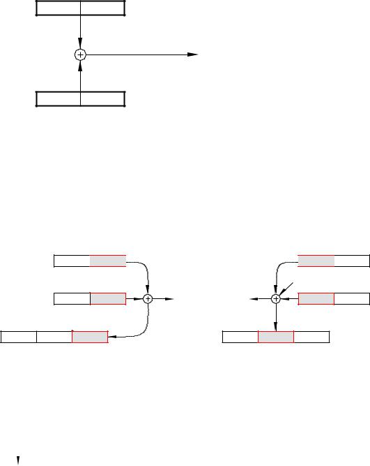
Although BASIC is only capable of directly implementing 8-bit arithmetic, operations of any length are possible by breaking down the process into byte-sized chunks. In the case of addition, this involves a sequence of byte operations from the least to the most significant digits with any carry from the nth digit byte being added into the n+1th summation. The least significant addition has a presumed carry-in of 0 and the carry-out from
3. Stored Program Processing 65
the most significant addition becomes the highest bit of the outcome. For example FF FFh + FF FFh = 1 FF FFh (65, 535d + 65, 635d = 131, 070d).
F20h F21h
AUGEND_H AUGEND_L
F24h |
F25h |
F26h |
SUM_H |
SUM_M |
SUM_L |
F22h F23h
ADDEND_H ADDEND_L
Fig. 3.8 The process.
The overall process is diagrammatically shown in Fig. 3.8. However, given that we need to implement the process as a sequence of steps executable by the byte-sized instructions of Table 3.1 then the next step is to produce a task listing.
1.Add the low bytes of the augend and addend, generating the low byte of the sum and carry C1.
F20h F21h
AUGEND_H  AUGEND_L
F20h F21h
 AUGEND_H
 AUGEND_L
|
|
|
|
|
|
C1 |
|
|
|
|
F22h |
F23h |
|
|
|
F22h |
F23h |
|
ADDEND_H ADDEND_L |
C1 |
C2 |
|
ADDEND_H ADDEND_L |
|||
F24h |
F25h |
F26h |
|
|
F24h |
F25h |
F26h |
|
SUM_H |
SUM_M |
SUM_L |
|
|
SUM_H |
SUM_M |
SUM_L |
|
(a) Adding the least-significant bytes |
(b) |
And the most-significant bytes |
|
|||||
|
|
|
|
F20h |
|
F21h |
|
|
|
AUGEND_H |
AUGEND_L |
||
|
|
|
|
|
|
|
C2 |
|
|
F22h |
|
F23h |
|
|
ADDEND_H |
ADDEND_L |
||||
|
|
|
||||
|
F24h |
|
F25h |
|
F26h |
|
SUM_H |
SUM_M |
SUM_L |
|
|||
|
|
|
|
|
|
|
(c) The most-significant sum byte is the last carry-out
Fig. 3.9 Visualization of the task process.

66The Quintessential PIC Microcontroller
2.Add the high bytes of the augend and addend plus the last carry-out C1 to give the middle byte of the sum and a new carry-out C2.
3.The high byte of the sum is the last carry-out C2, either 0 or 1.
Given that this is our first program of any substance, a detailed visualization of this task list will be useful. For most instances detail at this level is not helpful and subsequently we will use a more abstract visualization known as a flow chart (see Example 3.3).
Once a task list has been established then the next step is to implement this as a sequence of instructions, that is the program. One possible is shown in Program 3.5.
In the listing the three tasks are identified by an appropriate comment.
Task 1
This comprises a Load-Add-Store sequence to add the lower byte of the addend to that of the similarly significant augend. The outcome byte is
Program 3.5 The double-precision add program.
AUGEND_H |
equ 020h |
|
|
AUGEND_L |
equ 021h |
|
|
ADDEND_H |
equ 022h |
|
|
ADDEND_L |
equ 023h |
|
|
SUM_H |
equ 024h |
|
|
SUM_M |
equ 025h |
|
|
SUM_L |
equ 026h |
|
|
STATUS |
equ |
03 |
; STATUS flag register |
C |
equ |
0 |
; The C flag |
DP_ADD |
clrf |
SUM_M |
; Zero the 2 upper bytes of the sum |
|
clrf |
SUM_H |
|
; Task 1 |
|
|
|
|
movf |
AUGEND_L,w |
; Get LSB of the augend |
|
addwf |
ADDEND_L,w |
; Add LSB of addend |
|
movwf |
SUM_L |
; and put it away |
; Tasks 2 and 3 |
|
|
|
|
btfsc |
STATUS,C |
; Was there a carry C1? |
|
incf |
SUM_M |
; IF yes THEN add to middle sum byte |
|
movf |
AUGEND_H,w |
; Get MSB of the augend |
|
addwf |
ADDEND_H,w |
; Now add to MSB of the addend |
|
btfsc |
STATUS,C |
; Was there a carry C2? |
|
incf |
SUM_H |
; IF so THEN add to high byte sum |
|
addwf |
SUM_M,f |
; Add the outcome to mid sum byte |
|
btfsc |
STATUS,C |
; Was there a carry C2 from this? |
|
incf |
SUM_H |
; IF so THEN add to high sum byte |
|
.... |
..... |
; Next program |
|
|
|
|
3. Stored Program Processing 67
stored in memory at File 26h (SUM_L) and the Carry flag bit (bit 0 in File 3) is set as appropriate to C1.
Task 2
If there was a carry-out from Task 1 then the precleared middle byte of the sum is incremented as the carry-in C1. Then the upper bytes of the addend and augend are added. The final outcome of SUM_M (in File 25h) is determined by adding its current state (00h or 01h) to the outcome of this addition.
Task 3
Either of the two additions in Task 2 can result in a carry-out. The C flag in the STATUS register can be tested after each addition and if set, the upper byte of the sum SUM_H (File 26h) is incremented to add C2, as shown in Fig. 3.8(c). There will not be a carry-out generated by both the Task 2 additions.
Example 3.3
Write a program to divide the byte in the Working register by ten. The quotient is to be in File 20h and the remainder in W.
Solution
Division is the process in finding how many times the divisor (ten in our case) can be subtracted from the dividend without underflowing, that is producing a borrow.
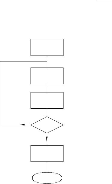
The flow chart shown in Fig. 3.10 outlines the task list to implement our algorithm. Initializing the quotient to −1 means that the subtract and increment loop can begin by incrementing, and this process will continue until a borrow is produced after the subtraction by ten process. A
Program 3.6 Dividing by ten.
QUOTIENT |
equ |
020h |
; Where the quotient will be stored |
|
STATUS |
equ |
03 |
; Where STATUS reg. flags are located |
|
DIV_10 |
clrf |
QUOTIENT |
; 1: Zero quotient |
|
|
decf |
QUOTIENT,f |
; 1: Initial value is -1 |
|
DIV_LOOP |
incf |
QUOTIENT,f |
; 2: Increment quotient |
|
|
addlw |
-10 |
; 3: Subtract ten from dividend |
|
|
btfsc |
STATUS,0 |
; 4: Leave loop if borrow (bit 0 = 0) |
|
|
goto |
DIV_LOOP |
; 4: ELSE repeat increment and subtract |
|
|
addlw |
10 |
; 5: Add ten to give remainder |
|
|
.... ..... |
; Next program |
||
|
|
|
|
|
68 The Quintessential PIC Microcontroller
borrow-out indicates that the last subtraction was not successful in that the divisor (i.e. ten) was larger than the residue it was subtracted from. That is the outcome is negative. The loop count on exit represents the number of successful subtractions and thus the quotient.
The coding in Program 3.6 closely follows the flow chart, with comment numbers referring to the statement boxes. The actual subtract constant ten is implemented by adding minus ten! This is because the more obvious sublw 10 instruction actually subtracts W from ten and not ten from W. Notice the mechanism for exiting the loop by testing and skipping if bit 0 in STATUS is clear after this subtraction.
Remembering that bit 0 in File 3 is the Carry flag doubling as the Borrow flag, then a borrow out is indicated if this bit is zero after the subtraction. On exit ten is added back on to compensate for the last unsuccessful subtraction and the outcome then gives the remainder.
Quotient = |
-1 |
LOOP |
|
Increment |
|
quotient |
|
Subtract ten |
|
from dividend |
|
No |
|
Borrow? |
|
Yes |
|
Add ten to give remainder
End
Fig. 3.10 Division by repetitive subtracting.

3. Stored Program Processing 69
Example 3.4
As part of a program to convert degrees Celsius to Fahrenheit it is necessary to multiply the byte in W by nine. Devise a suitable coding.
Solution
There are two ways of multiplying. The fundamental definition of multiplication is repetitive addition, thus we could add the datum nine times to implement our specified function. An alternative approach is the shift and add technique outlined on page 11. Thus the ×9 function is implemented as ×8 +×1. The former is carried out by shifting left three times (i.e. 23). Thus we have:
W × 9 = W × 8 + W × 1 = (W << 3) + W
No matter what technique is used, the outcome by definition will be larger than either the multiplier or multiplicand. In this case we need two bytes. In the coding of Program 3.7 the two memory locations File 20h and File 21h are used to hold the high byte and the low byte respectively of the final 2-byte product. By copying the multiplicand from W to the low byte and clearing the upper byte we make an extended 2-byte version of the multiplicand in Data memory. Shifting left is implemented by using
Program 3.7 Multiplying by nine.
STATUS |
equ |
3 |
; STATUS register flags |
C |
equ |
0 |
; Carry flag is bit0 |
PRODUCT_H equ 020h |
; High byte of the product |
||
PRODUCT_L equ 021h |
; Low byte |
||
MUL_9 |
movwf |
PRODUCT_L |
; Move the multiplicand to memory |
|
clrf |
PRODUCT_H |
; Extend it to 2 bytes |
; Now shift the double byte multplicand three times to give x8
bcf |
STATUS,C |
; |
Clear carry |
|
rlf |
PRODUCT_L,f ; |
Shift left low byte of product |
||
rlf |
PRODUCT_H,f ; |
and |
the high byte |
|
bcf |
STATUS,C |
; |
Clear carry |
|
rlf |
PRODUCT_L,f ; |
Shift left low byte of product |
||
rlf |
PRODUCT_H,f ; |
and |
the high byte |
|
bcf |
STATUS,C |
; |
Clear carry |
|
rlf |
PRODUCT_L,f ; |
Shift left low byte of product |
||
rlf |
PRODUCT_H,f ; |
and |
the high byte |
|
; Now add the original value giving |
x8 + x1 = x9 |
|||
addwf |
PRODUCT_L,f ; |
Add |
to lower byte |
|
btfsc |
STATUS,C |
; |
and |
any carry to the upper byte |
incf |
PRODUCT_H,f |
|
|
|
end |
|
|
|
|
|
|
|
|
|
70 The Quintessential PIC Microcontroller
C
0
PRODUCT_L
1 bcf CCR,C
C
2 rlf PRODUCT_L,f
PRODUCT_H
3 rlf PRODUCT_H,f
Fig. 3.11 Double-precision shifting.
the rlf (Rotate Left File) instruction twice, beginning with the lower byte. As well as shifting the byte PRODUCT_L left once, the most significant bit is moved into the Carry flag. Subsequently rotating the contents of the high byte PRODUCT_H moves this Carry in as the new least significant bit and shifts the high byte left as shown in Fig. 3.11. Of course the Carry flag needs to be cleared prior to this process. This 3-instruction double-precision routine is repeated three times to give the required ×8 function. Adding the original multiplicand, which is still in W gives the final ×9 function.
Example 3.5
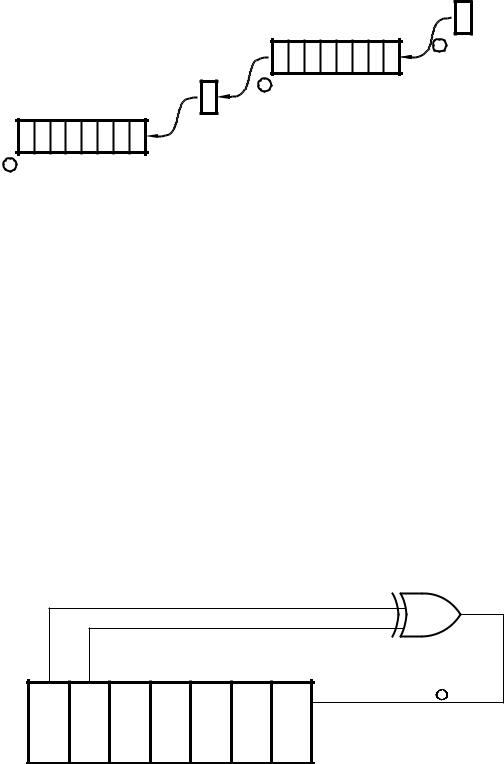
The circuit diagram of Fig. 3.12 shows a 7-bit pseudo-random number generator (PRNG) based on a shift register with an Exclusive-OR gate feedback. Devise a routine to continually send these 127 binary random numbers to a port located at File 06. The routine must initialize the PRN to any non-zero value.
1D |
Data in = B5 + B6 |
|
B6 B5 B4 B3 B2 B1 B0
C1 Sample rate
Fig. 3.12 A 7-bit pseudo-random number generator.

3. Stored Program Processing 71
Solution
A suitable task list is:
1.Initialize the number to 01.
2.DO forever.
(a)Rotate shift a copy of the number once left so that bits 5 & 6 are aligned.
(b)Bitwise XOR the number and its shifted copy.
(c)Rotate the outcome twice left to pop out bit 6 into the C flag, which will be B6 B5.
(d)Rotate the original number once left with C becoming the new bit 0.
Program 3.8 A 7-bit pseudo-random number generator.
PORTB |
equ |
6 |
|
|
NUMBER |
equ |
0x20 |
|
|
TEMP |
equ |
0x21 |
|
|
PRNG |
movlw |
1 |
; Initial value of random number is 01 |
|
P_LOOP |
movwf |
NUMBER |
; Make a copy in memory |
|
|
rlf |
NUMBER,f |
; Shift number to align bits 5 & 6 |
|
|
xorwf |
NUMBER,f |
; Bitwize XOR them |
|
|
rlf |
NUMBER,f |
; Shift twice left to put 5XOR6 in Carry |
|
|
rlf |
NUMBER,f |
|
|
|
movwf |
TEMP,f |
; Put original number in memory |
|
|
rlf |
TEMP,w |
; >> with carry coming in, and put in W |
|
|
movwf |
PORTB |
; and send this new random number out |
|
|
goto |
P_LOOP |
; and repeat |
|
|
|
|
|
|
The listing in Program 3.8 follows the task list fairly closely. The value of the number is temporarily saved in memory so that it can be processed without altering the original number down in W. This is done by specifying the destination to be the file, eg. rlf NUMBER,f. After rotating left once left, bit 5 in the shifted copy in NUMBER is aligned with the original bit 6 in W. After exclusive ORing the two, with the destination again being in File memory (xorwf NUMBER,f), bit 6 in NUMBER is now B5 B6. Shifting twice left puts this bit in the Carry flag. Finally rotating the original pseudo-random number in W moves that pattern once left with the new least-significant bit being the Carry flag, that is B5 B6 as specified in the diagram. The first 32 hexadecimal values output are:
02 04 08 10 20 41 83 06 0C 18 30 61 C2 85 0A 14

72 The Quintessential PIC Microcontroller
28 51 A3 47 8F 1E 3C 79 F2 E4 C8 91 22 45 8B 16 …
The sequence will repeat after 127 output values.
What would happen if the initial value of the random number was zero?
Self-assessment questions
3.1How could you simply with one instruction toggle bit 0 of any file register?
3.2As part of a Data memory testing procedure each file in the range File 0Ch through File 2Fh is to be set to the pattern 01010101b (55h). Using Program 3.2 as a model, write a suitable coding to implement this task.
3.3Write a program to subtract the double-byte datum which is located in File 22:23h, called NUM_2, from NUM_1 in File 20:21h. The doublebyte di erence is to be in File 24:25h. Remember, if there is a borrow from the lower byte subtraction then an additional one must be subtracted from NUM_1 in the upper byte subtraction. Assume that NUM_2 is smaller or equal to NUM_1. If this were not so how could you determine this situation after the routine has been completed?
3.4Write a routine that will determine how many hundreds there are
in a byte in Data memory at File 20h. The outcome, which is to be in W, will either be 02h, 01h or 00h. For example if the contents of File 20 are FFh (decimal 255) then the outcome will be two. Hint: Try subtracting the number 200 from that in W and examining the Carry/borrow flag. If no borrow then try 100. Again if no borrow then the number must be less than 100.
3.5 The binary approximation to the fraction 13 is:
1 1 1 1 1 1 1 1 3 = 2 − 4 + 8 − 16 + 32 − 64 + 128 · · ·
Using this series, write a program that will divide a byte in the Working register by three, with the quotient being in the same register at the end. You can use File 20h and File 21h as temporary storage for the quotient and shifting number respectively. The outcome up to 1281 is 0.3359375, which is within 0.78% of the exact value. With an 8-bit datum there is no point in including any further elements in the series.
3. Stored Program Processing 73
3.6Write a routine that will count the number of ones in the Working register. For example if W were 01110011b then the outcome in File 20h would be 05h. Hint: Continually shift the number, while incrementing the count when the shifted-out bit in the Carry flag is one. Either do this eight times or else exit when the residue is zero. Remember if taking the latter approach that the Carry flag must be cleared before rotating the number! You may use File 21h as a temporary store for the shifting number.
3.7Data from an array of data memory between File 30h and File 4Fh is to be transmitted byte by byte to a distant computer over the internet. In order to allow the receiver to examine the data and check for transmission errors it is proposed to append a single byte which is the 2’s complement (i.e. the negative value, see page 9) of the 8-bit sum of all the data bytes together. If all the received data bytes plus this checksum byte are similarly added then the outcome should be zero if no error has occurred. Code a routine to scan through this data, placing this checksum in File 20h. See Example 3.2 for a template.
3.8One simple way of encrypting a data byte is to reverse the order of bits. For example 10111100b → 00111101b. Write a routine to implement this reversal on a data byte in File 20h. The encrypted outcome is to be in the Working register. You can use location File 21h as a temporary workspace and W as a loop counter. Hint: Use the Rotate Right and Rotate Left File instruction eight times. If you use W as the loop register then use the instruction addlw -1 as a decrement W operation.
3.9Parity is a simple technique to protect digital data from corruption by noise. Odd parity adds a single bit to a word in such a way as to ensure the overall packet has an odd number of 1s. Write a routine that takes an 8-bit byte stored at File 20h and alters its most significant bit to comply with this specification. You can assume that bit 7 is always 0 before the routine begins. Hint: Determine if a binary number is odd or even by counting the number of bits as in SAQ 3.6 and then
examining its least significant bit. All powers of two are even except 20 = 1. Thus if this bit is 1 then the number is odd.