


CHAPTER 16
A Case Study
Up to this point our microcontroller material has been presented piecemeal. To complete our study we are going to put much of what we have learnt to good use and design both the hardware and software of an actual widget (gadget). This is not an easy task to do in a single short chapter. However, very little new material needs to be presented at this point, rather a process of coalescence.
We begin with our specification. Students invariably talk too long during their oral presentations. It is proposed that a dedicated embedded microcontroller-based system be designed to act as a time monitor. This monitor should default to a time-out of 10 minutes, but will have the provision to vary the allotted time from 1 to 99 minutes.
Once triggered, the monitor should perform the following sequence of operations:
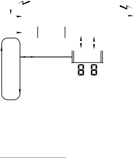
1.When the GO switch is closed, a green lamp will illuminate and a
dual seven-segment display will show a count-down from the timeout value to 

 at one-minute intervals.
2.After a further minute, an amber lamp only will illuminate, the count of 

 will be displayed and a buzzer will sound for nominally one second.
3.After a further minute, a red lamp only will illuminate together with a display of 

 . The buzzer will sound for two seconds.
4.Finally, after another minute the display will show 

 , the red lamp will continue to be illuminated and the buzzer will sound continuously until the STOP switch is pressed. This will halt the timer and turn o all displays, lamps and buzzer. Indeed, closing the STOP switch at any time during the sequence above will cause the system to permanently halt. The system may be restarted from the time-out value by resetting the processor.
5.At any time the sequence can be frozen by toggling the PAUSE switch. When toggled again, the sequence will continue on from where it left o .
6.In order to alter the time-out from the default value of 

 , the SET switch must be closed when the system is reset. The display will then show

 and will count down slowly. The value showing when the

16. A Case Study 457
Switches
The five switches S2…S6 implementing the functions GO, SET, STOP, DIAG, PAUSE are read from Port B at RB[4:0]. By using this port’s internal pull-up resistors (see Fig 11.7 on page 280) no external resistors are required.
S1 with R1 provides a Manual reset in order to restart the count. This MCLR signal also provides a Reset signal feed for external circuitry.
All six switches can be conveniently implemented as momentary contact keyboard switches.
Lamps
Three suitably colored 10 mm (0.4") high-brightness LEDs D3…D1 driven from RB[7:5] provide the light signals. 330Ω series resistors limit the current to nominally 10 mA.
Buzzer
The buzzer should be a miniature solid-state device. A typical piezoelectric implementation will operate over a wide d.c. voltage range of typically 3–16 V and require little more than 1 mA at 5 V.1
The buzzer is driven via RA2.
Numerical display
Two 7-segment displays give the required 2-digit read-out, facilitating the maximum specified period of 99 minutes. As only four port pins remain, a serial interface is implemented. This is similar to that shown in Fig. 12.2 on page 307 but each SIPO shift register has a separate data feed, with RA0 being used for the ten’s digit and RA3 for the units digit. Both digits can therefore be simultaneously updated with eight shifts.
The common-anode seven-segment display pinning shown in the diagram is that of the 16-pin Dual In Line (DIL) footprint with both left and right decimal points – lhdp and rhdp. Only the latter is used here (to indicate that the system has paused) in conjunction with the 8-bit 74HC164 shift register. Alternative 16and 14-pinouts are commonly available and even dual-digit packages. However, even the 16-pin footprint pinout is not standardized.
Smaller-sized displays, typically below 0.8 /20 mm, use a single LED for each bar, with a conducting voltage drop of around 2 V.2 The DIL 330 Ω series resistors R5 and R6 limit the current to around 10 mA. The common anodes are connected directly back to the normal +5 V power supply to avoid current surges a ecting the logic circuits, and should be decoupled by small tantalum capacitors. Although the displays are normally rated for 20 mA, restricting the current to this value gives suf-
1If you want to put paid to any possibility of the speaker continuing, a piezo-electric sound bomb producing 110 dB at 1 m distance needs a 12 V d.c. supply at 200 mA.
2Larger displays, e.g. 2.24 /56 mm, have typically two or four LEDs in series. In the latter case a separate 12 V supply would be needed and current bu ering.
 STOP
STOP
16. A Case Study 459
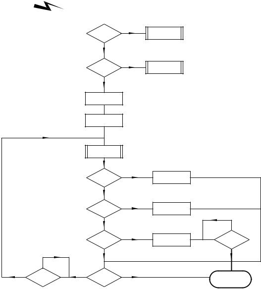
Timebase task
All processes are time related. Timekeeping is implemented in hardware by generating an interrupt 50 times each second. By keeping a Ji y count, seconds and minute tasks are updated and are used to sequence the appropriate process.
By monitoring the PAUSE switch this decrementing time chain can be by-passed, hence freezing the countdown for as long as necessary.
Display task
All processes need to output the state of the count or status information to the two 7-segment displays. As this involves parallel to serial conversion and shifting, the task is better gathered into one module.
Main process
The Main process is a loop displaying the Minute count until it reaches zero, with a premature break if the STOP switch is closed.
Set-time process
If the SET switch is closed when the PIC is reset then the SET_TIME subroutine quickly decrements the display count until the switch is released. This displayed value is then written into Data EEPROM and is used by all subsequent Main processes as the starting value for the Minute count.
Diagnostic process
If the DIAG switch is closed on reset, the system enters a diagnostic subroutine. The essentially exercises each peripheral device in a manner calculated to ease hardware fault finding.
All processes are dependent on the Timebase task to pass basic realtime clock information back. As shown in Program 16.1 this is interrupt driven and is based on the Timer 0:Prescaler dividing down the 3.2763 MHz crystal-driven oscillator to give overflow every 501 s. As can be seen in Program 16.3, the Timer 0 interrupt is enabled and thus the PIC will enter ISR whenever the timer overflows – every 256 outputs from the Prescaler. Remembering that the crystal oscillator runs at 14 of the crystal frequency, a prescale ratio of 1:64 will give a timebase rate of 50
per second – 3.2763×106 = 50.
4×64×256
The task list for this function is:
1.IF PAUSE switch open THEN
(a)Decrement the time chain by one Ji y.
(b)IF new second THEN flag it.
2.ELSE
(a)Toggle the Pause flag.
(b)IF set THEN tell the world that the system is paused.
(c)ELSE display time to indicate normal running.
(d)Wait until PAUSE switch is released.
3.Return from interrupt.

460 The Quintessential PIC Microcontroller
Program 16.1 The timebase software. (continued next page).
; *************************************************************
; * |
The ISR to decrement the real-time clock |
* |
|
; |
* |
Adding a 20ms Jiffy on each entry |
* |
; |
* |
Sets NEW_SEC to a non-zero value each Minute update |
* |
;*************************************************************
;First save context in usual way
ISR |
movwf |
_work |
; |
Put |
away W |
|
swapf |
STATUS,w |
; |
and |
the Status register |
|
movwf |
_status |
|
|
|
;*************************************************************
;The core code
btfss |
INTCON,T0IF |
; Was it a Timer0 time-out? |
goto |
ISR_EXIT |
; IF no THEN false alarm |
btfsc |
Pause,0 |
; Check the Pause flag |
goto |
ISR_EXIT |
; IF closed THEN don’t increment |
bcf |
INTCON,T0IF |
; Clear interrupt flag |
incf |
JIFFY,f |
; Record one more 1/50 second |
movlw |
d’50’ |
; Has Jiffy count reached 50? |
subwf |
JIFFY,w |
|
btfss |
STATUS,Z |
|
goto |
ISR_EXIT |
; IF not THEN finished |
clrf |
JIFFY |
; ELSE zero Jiffy count |
movf |
SECOND,f |
; Test for Seconds count = 00? |
btfsc |
STATUS,Z |
|
goto |
NEW_MIN |
; IF it is THEN a NEW_SEC minute |
decf |
SECOND,f |
; ELSE decrement Seconds count and |
incf |
NEW_SEC,f |
; tell background prog new second |
goto |
ISR_EXIT |
; and exit |
NEW_MIN movlw |
d’59’ |
; Reset Seconds to 59 seconds |
movwf |
SECOND |
|
movf |
MINUTE,f |
; Test for Minutes count = 00? |
btfsc |
STATUS,Z |
|
goto |
ISR_EXIT |
; IF it is THEN no more decrement |
decf |
MINUTE,f |
; ELSE decrement Minutes |
; ************************************************************
ISR_EXIT btfss |
PORTB,PAUSE |
; Check the PAUSE |
switch |
call |
FREEZE |
; IF closed THEN update Pause flag |
|
swapf |
_status,w |
; Untwist the original Status reg |
|
movwf |
STATUS |
|
|
swapf |
_work,f |
; Get the original |
W reg back |
swapf |
_work,w |
; leaving STATUS unchanged |
|
retfie |
|
; and return from |
interrupt |
|
|
|
|

16. A Case Study 461
Program 16.1 (continued.) The timebase software.
; *************************************************************
; * FUNCTION: |
Increments the Pause |
flag. |
* |
||
; * FUNCTION: |
IF = 1 |
THEN displays |
the decimal points |
* |
|
; * FUNCTION: |
IF = 0 |
THEN displays |
the normal count |
* |
|
; * RESOURCE: |
Subroutine SPI_WRITE. Var Pause |
* |
|||
; * ENTRY |
: |
PAUSE switch closed |
|
* |
|
; * EXIT |
: |
Pause switch open; appropriate display |
* |
||
; *************************************************************
FREEZE incf |
Pause,f |
; Update Pause flag, bit 0 |
btfss |
Pause,0 |
; Check status of Pause flag |
goto |
UNFREEZE |
; Change 1 -> 0, unfreeze |
; Display freeze |
|
|
movlw |
b’01111111’ ; Code for display decimal point |
|
movwf |
DATA_OUT_L |
|
movwf |
DATA_OUT_H |
|
call |
SPI_WRITE |
|
goto |
FREEZE_EXIT |
|
UNFREEZE ; Land |
here if Pause 0 -> 1. |
|
movf |
MINUTE,w |
; Display the normal Minute count |
call |
OUTPUT |
|
FREEZE_EXIT
btfss PORTB,PAUSE ; Wait til switch is opened again goto FREEZE_EXIT
return
From Program 16.1 we see that time is kept as a 3-byte count chain using file registers MINUTE, SECOND and JIFFY to hold the total. Assuming that the state of bit 0 of file register Pause is 0, then one is added to the Ji y count. Normally the ISR then exits but when Ji y reaches 50 it is reset to zero and the Seconds count decremented. The file register NEW_SEC is also made non zero to indicate to background software that a second has elapsed. In the situation where the Second count reaches zero then it is reset to 59 and the Minute count decremented. The procedure is similar to the incrementing count of Example 7.4.
The Timebase task also handles the Pause function. The simplest approach would be to skip over the time decrement code if the PAUSE switch is closed. However, the necessity to keep the switch closed could be irksome if the period was more than a few minutes.
Implementing a push-on push-o scenario is ergonomically superior and can be more economically implemented in software rather than using a di erent type of switch compared to the others. In Program 16.1 the Pause handling code is located in the separate subroutine FREEZE. It is permissible to call a subroutine from an ISR in the same manner as calling one subroutine from another; that is nesting. The 8-deep hardware stack

462 The Quintessential PIC Microcontroller
allows nesting up to eight deep. In our situation only two of the stack locations are used, allowing up to six calls deeper into the stack.
Subroutine FREEZE is only entered if the PAUSE switch is closed. On each entry the value of bit 0 of the file register Pause is toggled. This is implemented by simply incrementing file register Pause.
Once Pause[0] is toggled, its state is tested and if 1 the pattern to only illuminate the two decimal points is sent to the SPI_WRITE subroutine. This is an arbitrary indicator display, another possibility would be 

 . If Pause[0] is 0 then the state of the Minute count is sent to the OUTPUT subroutine and indicates to the user that the Pause function has ended.
Finally, the subroutine does not exit until the user releases the PAUSE switch. This is important, as on exit the ISR will be re-entered again at the next Timer 0 overflow, and this would cause Pause to be repeatedly retoggled. Some measure of switch debounce is obtained by zeroing Timer 0 and the Prescaler when the switch is released. This means that the switch will not be retested for a whole 501 second. It is for this reason that T0IF is cleared on exit from the ISR rather than at the more conventional entry point.
The task displaying the contents of the Working register in decimal is handled by the subroutine OUTPUT in Program 16.2. The task list for this function is:
1.Convert the binary datum to 2-digit BCD.
2.Convert both digits to 7-segment.
3.Serially shift out both bytes to the appropriate display.
Program 16.2 The data display function. (continued next page).
; *************************************************************
; * |
FUNCTION: |
Displays |
datum as a 2-digit decimal output |
* |
||||
; * |
RESOURCE: |
Subroutines |
BIN_2_BCD, SPI_WRITE, SVN_SEG |
* |
||||
; * |
RESOURCE: |
Vars |
DATA_OUT_L, DATA_OUT_H, NEW_SEC, NUMBER |
* |
||||
; |
* |
ENTRY |
: |
Datum in |
W, |
<100d |
* |
|
; |
* |
EXIT |
: |
Data |
displayed, NEW_SEC zeroed |
* |
||
; *************************************************************
OUTPUT bcf |
PORTA,SCK |
; Initialize the clock line |
|
call |
BIN_2_BCD |
; Convert to BCD |
|
movwf |
NUMBER |
; Put BCD MINUTE version in NUMBER |
|
movf |
NUMBER,w |
; Get number count for display |
|
andlw |
b’00001111’ |
; Get Units nybble |
|
call |
SVN_SEG |
; Convert to 7-segment code |
|
movwf |
DATA_OUT_L |
; Copy into the serial low register |
|
swapf |
NUMBER,w |
; Put ten’s digit into lower nybble |
|
andlw |
b’00001111’ |
; Isolate ten’s digit |
|
call |
SVN_SEG |
; Convert to 7-segment code |
|
movwf |
DATA_OUT_H |
; Copy into the serial high register |
|
call |
SPI_WRITE |
; Shift both digits out |
|
clrf |
NEW_SEC |
; Reset NEW_SEC flag |
|
|
|
|
|

16. A Case Study 463
Program 16.2 (continued.) The data display function.
; *******************************************************
; * |
FUNCTION: |
Clocks out a two |
byte |
in parallel/series |
* |
||||
; * |
ENTRY |
: |
Data in DATA_OUT_L and DATA_OUT_H |
* |
|||||
; |
* |
ENTRY |
: |
The former |
to be |
LSD, |
the |
latter MSD |
* |
; |
* |
EXIT |
: |
DATA_OUT_L |
and DATA_OUT_H |
altered |
* |
||
; *******************************************************
SPI_WRITE |
|
|
|
|
bcf |
PORTA,SCK |
; Make sure clock starts at low |
|
movlw |
8 |
; Initialize loop counter to 8 |
|
movwf |
COUNT |
|
LOOP |
bcf |
PORTA,SDOH |
; Zero data bit for MSD |
|
rlf |
DATA_OUT_H,f |
; Shift datum left into Carry |
|
btfsc |
STATUS,C |
; Skip if Carry is 0 |
|
bsf |
PORTA,SDOH |
; ELSE make data bit 1 |
|
bcf |
PORTA,SDOL |
; Zero data bit for LSD |
|
rlf |
DATA_OUT_L,f |
; Shift datum left into Carry |
|
btfsc |
STATUS,C |
; Skip if Carry is 0 |
|
bsf |
PORTA,SDOL |
; ELSE make data bit 1 |
|
bsf |
PORTA,SCK |
; Pulse clock |
|
bcf |
PORTA,SCK |
|
|
decfsz |
COUNT,f |
; Decrement count |
|
goto |
LOOP |
; and repeat until zero |
return SVN_SEG addwf PCL,f
retlw b’11000000’ retlw b’11111001’ retlw b’10100100’ retlw b’10110000’ retlw b’10011001’ retlw b’10010010’ retlw b’10000010’ retlw b’11111000’ retlw b’10000000’ retlw b’10010000’
; *************************************************************
; * |
FUNCTION: |
Converts a |
binary byte |
to |
a |
packed |
BCD byte |
* |
|||
; * |
RESOURCE: |
TEMP byte |
|
|
|
|
|
* |
|||
; |
* |
ENTRY |
: |
Binary |
byte in W range |
00 |
- |
63h (0 |
- 99d) |
* |
|
; |
* |
EXIT |
: |
Packed |
BCD |
byte in W |
|
|
|
|
* |
;*************************************************************
;Divide by ten
BIN_2_BCD clrf |
TEMP |
; Zero the loop count |
|
LOOP10 |
incf |
TEMP,f |
; Record one ten subtracted |
|
addlw |
-d’10’ |
; Subtract decimal ten |
|
btfsc |
STATUS,C |
; IF a borrow (C==0) THEN exit loop |
|
goto |
LOOP10 |
; ELSE do another subtract/count |
|
decf |
TEMP,f |
; Compensate for one inc too many |
|
addlw |
d’10’ |
; Add ten to residue to give units |
|
swapf |
TEMP,f |
; Put ten’s digit in upper nybble |
|
addwf |
TEMP,w |
; Add units nybble right justified |
|
return |
|
; and return to caller |
|
|
|
|

16. A Case Study 465
|
|
Program 16.3 The initialization code. |
||
|
|
|
|
|
|
include |
"p16f84.inc" |
|
|
SDOH |
equ 0 |
|
|
|
SCK |
equ 1 |
|
|
|
BUZ |
equ 2 |
|
|
|
SDOL |
equ 3 |
|
|
|
GREEN |
equ 5 |
|
|
|
YELLOW |
equ 6 |
|
|
|
RED |
equ 7 |
|
|
|
PAUSE |
equ 0 |
|
|
|
DIAG |
equ 1 |
|
|
|
STOP |
equ 2 |
|
|
|
SETT |
equ 3 |
|
|
|
GO |
equ 4 |
|
|
|
|
cblock |
20h |
|
JIFFY:1, NUMBER:1, NEW_SEC:1 |
|
MINUTE:1, SECOND:1, |
|||
|
DATA_OUT_L:1, DATA_OUT_H, COUNT:1, TEMP:1, TIME_OUT:1 |
|||
|
Pause:1, _work:1, _status:1 |
|||
|
endc |
|
|
|
|
__config _XT_OSC & _WDT_OFF & _PWRTE_ON & _CP_OFF |
|||
|
org |
2100h |
; |
The EEPROM Data module |
|
de |
d’10’ |
; |
Default value is 10 minutes |
RESET |
org |
0 |
; |
Reset vector |
|
goto |
MAIN |
|
|
|
org |
4 |
; |
Interrupt vector |
|
goto |
ISR |
|
|
MAIN |
bsf |
STATUS,RP0 |
; |
Change to Bank 1 |
|
movlw |
b’11100000’ ; |
RA4:0 outputs |
|
|
movwf |
TRISA |
|
RB7:5 outputs; RB4:0 inputs |
|
movlw |
b’00011111’ ; |
||
|
movwf |
TRISB |
|
Clock TMR0 internally; assigned PS |
|
movlw |
b’00000101’ ; |
||
|
movwf |
OPTION_REG |
; |
Set to 1:64. Enable PORTB pull-ups |
|
bcf |
STATUS,RP0 |
; |
Back to Bank 0 |
|
clrf |
Pause |
; |
The PAUSE switch toggle |
|
clrf |
NEW_SEC |
; |
Reset NEW_SEC second flag |
|
clrf |
TMR0 |
|
|
|
bcf |
INTCON,T0IF |
|
|
|
bsf |
INTCON,T0IE ; |
Enable Timer0 interrupts |
|
|
bsf |
INTCON,GIE |
; |
Enable all interrupts |
|
btfss |
PORTB,SETT |
; |
Check the Set switch |
|
call |
SET_TIME |
; |
IF closed THEN set total time |
|
btfss |
PORTB,DIAG |
; |
Check the Diagnostic switch |
|
call |
DIAGNOSTIC |
; |
IF closed THEN set total time |
|
|
|
|
|
If the DIAG switch is closed when the PIC comes out of reset then the code transfers to the subroutine DIAGNOSTIC.
The Diagnostic process aims to exercise the various peripheral devices interfaced to the process in order to verify in a reproducible manner the status of the interconnection and the devices themselves.

466 The Quintessential PIC Microcontroller
Switches
Five switches are input via Port B. By checking each switch in turn and if closed lighting one of the LEDs or sounding the buzzer both switches and the listed output devices are tested. The DIAG switch is of course verified by moving the system into this process and the Reset switch is tested by initiating the startup process.
If there were more switches than output devices then either combinations of the latter could be activated or else one or more segments in the numerical display pushed into service.
Program 16.4 The Diagnostic process.
;*************************************************************
;* FUNCTION: Checks each switch and activates a corresponding*
; * FUNCTION: |
LED or buzzer. Continually activates a unary |
* |
|
; * FUNCTION: |
pattern to both 7-segment displays |
* |
|
; * RESOURCE: |
Subroutines SPI_WRITE |
* |
|
; * RESOURCE: |
Vars TEMP, DATA_OUT_H, DATA_OUT_L |
* |
|
; * ENTRY |
: |
DIAG switch closed |
* |
; * EXIT |
: |
DIAG switch open |
* |
; *************************************************************
DIAGNOSTIC |
b’11111110’ |
; |
The initial 7-segment pattern |
|
|
movlw |
|||
|
movwf |
TEMP |
; |
in memory |
D_LOOP |
movlw |
b’11111111’ |
; |
Turn off all LEDs and buzzer |
|
movwf |
PORTB |
|
|
|
bsf |
PORTA,BUZ |
|
|
; Now scan switches |
|
|
||
|
btfss |
PORTB,PAUSE |
; |
IF Pause switch closed |
|
bcf |
PORTB,GREEN |
; |
THEN Green LED |
|
btfss |
PORTB,STOP |
; |
IF Stop switch closed |
|
bcf |
PORTB,YELLOW |
; |
THEN Yellow LED |
|
btfss |
PORTB,SETT |
; |
IF Set switch closed |
|
bcf |
PORTB,RED |
; |
THEN Red LED |
|
btfss |
PORTB,GO |
; |
IF Go switch closed |
|
bcf |
PORTA,BUZ |
; |
THEN Buzzer |
; Now turn on each segment in turn of both displays |
||||
|
movf |
TEMP,w |
; |
Get pattern |
|
movwf |
DATA_OUT_L ; |
Put in output file regs |
|
|
movwf |
DATA_OUT_H |
|
|
|
call |
SPI_WRITE |
; |
Display it |
|
btfsc |
PORTB,DIAG |
; |
IF Diagnostic switch open |
|
return |
|
; |
THEN exit the diag subroutine |
|
clrf |
NEW_SEC |
; |
Reset the New Second flag |
; Now move the display pattern |
on one and wait for a second |
|||
|
bcf |
STATUS,C |
; |
Clear Carry |
|
btfsc |
TEMP,7 |
; |
Check MSB of pattern |
|
bsf |
STATUS,C |
; |
IF 1 THEN Carry = 1 |
|
rlf |
TEMP,f |
; |
Shift it in << |
D_LOOP2 |
movf |
NEW_SEC,f |
; |
ELSE wait for the new second |
|
btfsc |
STATUS,Z |
; |
IF non zero THEN skip |
|
goto |
D_LOOP2 |
; |
ELSE try again |
|
goto |
D_LOOP |
; |
Repeat routine |
|
|
|
|
|
16. A Case Study 467
LEDs and buzzer
The static output devices are tested in conjunction with the switch test listed above. Of course the failure of a LED to light or buzzer to sound may be due to either the input or output device circuit. Determining which is easily accomplished by using a voltmeter or logic probe. Also all LEDs are illuminated during the Set-time process.
Display
Each of the display devices is exercised by lighting one segment moving on once each second in an endless loop. This is implemented by generating a walking unary pattern 11111110 → 11111101 → · · · 01111111 sent out to the output subroutine SPI_WRITE once each time the file register NEW_SEC is non zero. NEW_SEC is incremented in the Timer 0 interrupt-handling routine each time the Seconds count is incremented and cleared in the Diagnostic procedure code. This acts as a ratchet giving only one new display each second.
The Set-time process is entered when the SETT switch is closed whenever the processor comes out of reset. Its function is to allow the operator to change the contents of the EEPROM Data module location 00h to any value up to 99. This location holds the initial count-down value used by the Main process to determine the length of the procedure.
The strategy behind the coding shown in Program 16.5 is to initialize the Second count to 99 and let it decrement at a 1-second rate as
Program 16.5 The Set-time process.
; *************************************************************
; * |
FUNCTION: |
Slowly |
counts down |
from 99-00. When Set switch |
* |
|||
; * |
FUNCTION: |
released EEPROM is |
Written with NEW_SEC time-out* |
|||||
; * |
RESOURCE: |
Subroutines |
DISPLAY, EE_PUT, ISR; Var TIME_OUT |
* |
||||
; |
* |
ENTRY |
: |
Set switch is closed |
* |
|||
; |
* |
EXIT |
: |
EEPROM |
Data |
address 00 is updated |
* |
|
; *************************************************************
SET_TIME |
movlw |
d’99’ |
; Start count at 99 seconds |
|
|
movwf |
SECOND |
; All LEDs on |
|
|
movlw |
b’00000000’ |
||
|
movwf |
PORTB |
|
|
SET_LOOP |
movf |
SECOND,w |
; Get Second count |
|
|
call |
OUTPUT |
; Display it and clear NEW_SEC |
|
|
btfsc |
PORTB,SETT |
; Check; does the user want to stop? |
|
|
goto |
UPDATE |
; IF yes THEN update EEPROM and exit |
|
|
movf |
SECOND,w |
; Get displayed count |
|
|
movwf |
TIME_OUT |
; Make a temporary copy |
|
S_LOOP |
movf |
NEW_SEC,f |
; Check NEW_SEC status |
|
|
btfsc |
STATUS,Z |
; IF non zero THEN skip |
|
|
goto |
S_LOOP |
; ELSE try again |
|
|
goto |
SET_LOOP |
; Repeat display |
|
UPDATE |
movf |
TIME_OUT,w |
; Get the value |
|
|
movwf |
EEDATA |
; Set up EEPROM |
|
|
clrf |
EEADR |
; Program EEPROM |
|
|
call |
EE_PUT |
||
|
return |
|
; and return to main program |
|
|
|
|
|
|

16. A Case Study 469
the Main process. Although this looks rather complex, it may be broken down into five phases with corresponding coding shown in Program 16.6.
Preamble
On reset if neither SETT or DIAG switches are closed the Main procedure code is entered at MAIN_PROC. This reads the initial value of the countdown period from EEPROM location 00h and initializes the count chain. The green lamp is illuminated and other lamps and buzzer are turned o .
Countdown
The Countdown phase continually displays the Minute count – updated behind the scenes by the ISR. The green lamp remains illuminated as long as this display does not drop below 

 . This phase is complete whenever the count drops below 3 minutes or else the STOP switch is closed. In the latter case all displays are blanked and the PIC is put into its Sleep state.
In all situations except where the STOP command is issued the Minute count is displayed at 1-minute intervals. The routine at REPEAT checks the Second count and if zero the loop is repeated – that is once per minute. The simpler alternative of continually refreshing the 7-segment readouts gives an inferior display as the data being serially shifted at frequent rate may partially illuminate segments which are nominally o . In addition, repeating the loop each minute eases the task of sounding the buzzer once only when the Minute count drops to two and one.
Two minutes to go
When the display is 

 the amber lamp is illuminated This is timed using the NEW_SEC variable. Again the loop can be prematurely exited if the STOP switch has been closed.
One minute to go
When the display is 

 the loop diverts to illuminate the red lamp. The buzzer is sounded for two seconds; implemented in code as two 1-second buzzes.
Timed out
When the Minute count reaches zero, not only is 

 displayed but also the buzzer sounds continually. This cacophony can only be silenced by pressing the Stop switch – or by resetting and starting again. As in previous situations when the Stop switch is closed, all displays are blanked out and the PIC is placed in its Sleep state.
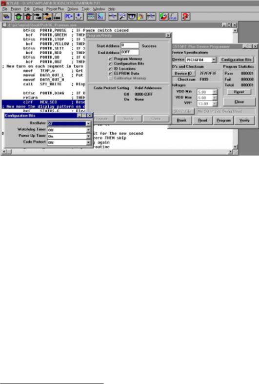
Once the source code has been assembled and where possible simulated (see Fig. 8.7 on page 222) it can then be burnt into the PIC’s Program store. In the first instance only the diagnostic software and associated tasks need be programmed in order to check the target hardware. The precise details will depend somewhat on the PIC programmer being used and its associated software.

470 The Quintessential PIC Microcontroller
Program 16.6 The Main process. (continued next page).
movlw |
b’11000000’ |
; Green LED on |
movwf |
PORTB |
|
bsf |
PORTA,BUZ |
; Buzzer off |
; Get start value from EEPROM |
|
|
clrf |
EEADR |
; EEPROM address zero |
call |
EE_GET |
; Get the start value |
movwf |
MINUTE |
|
movlw |
d’59’ |
; Initial value for seconds |
movwf |
SECOND |
; is 59 |
clrf |
JIFFY |
|
DISPLAY movf |
MINUTE,w |
; Get Minute count |
call |
OUTPUT |
; Output to display |
;The 2-minutes-to-go phase ***********************************
;At a count of two sound the buzzer for one second and turn on
;the amber lamp
TWO |
movf |
MINUTE,w |
; Minute count = 2? |
|
addlw |
-2 |
|
|
btfss |
STATUS,Z |
|
|
goto |
ONE |
; IF not THEN try for one minute |
|
movlw |
b’10100000’ |
; Amber LED on |
|
movwf |
PORTB |
|
|
bcf |
PORTA,BUZ |
; Buzzer on |
TWO_LOOP movf |
NEW_SEC,f |
; Check NEW_SEC status |
|
|
btfsc STATUS,Z |
; IF non zero THEN skip |
|
|
goto |
TWO_LOOP |
; ELSE try again |
|
bsf |
PORTA,BUZ |
; Turn off buzzer after one second |
|
goto |
REPEAT |
; repeat display |
;The 1-minute-to-go phase ************************************
;At a count of one sound the buzzer for two second and turn on
;the red lamp
ONE |
movf |
MINUTE,w |
; Minute count = 1? |
|
addlw |
-1 |
|
|
btfss |
STATUS,Z |
|
|
goto |
ZERO |
; IF not THEN try for zero minutes |
|
movlw |
b’01100000’ |
; Red LED on |
|
movwf |
PORTB |
|
|
bcf |
PORTA,BUZ |
; Buzzer on |
ONE_LOOP |
movf |
NEW_SEC,f |
; Check NEW_SEC status |
|
btfsc STATUS,Z |
; IF non zero THEN skip |
|
|
goto |
ONE_LOOP |
; ELSE try again |
|
clrf |
NEW_SEC |
; Again clear NEW_SEC flag |
UN_LOOP |
movf |
NEW_SEC,f |
; Again check NEW_SEC status |
|
btfsc STATUS,Z |
; IF non zero THEN skip |
|
|
goto |
UN_LOOP |
; ELSE try again |
|
bsf |
PORTA,BUZ |
; Turn off buzzer after two seconds |
|
goto |
REPEAT |
; Repeat display |
|
|
|
|

472 The Quintessential PIC Microcontroller
Fig. 16.4 Programming the PIC from MPLAB.
minute for the PIC16F84 and the 252 program words that this case study software generates.5
With F series PICs, the programming process may be repeated without any preparation of the Program store up to 100 times without any deterioration of the Flash EEPROM. C series PICS,6 such as the PIC16C74, have EPROM Program stores. Where the target has a quartz window it must be erased using a suitable UV-based EPROM eraser for approximately 20 minutes before programming, unless code is being added to previously unprogrammed memory. Although quartz windowed devices are necessary for development purposes, they are relatively expensive. Thus cheaper windowless version are used for production purposes, and are called One-Time Programmable (OTP) since they cannot subsequently be erased. Part numbers which are windowed are usually identified by JW postfix; for example, PIC16C74B-20/JW is a 20 MHz ceramic windowed PIC16C74B part and and the PIC16C74B-4/P is a 4 MHz OTP version in a 40-pin plastic DIL package. Ensure that you obtain the correct device!
The hardware and software circuits have been presented here as a simple illustrative case study to integrate many of the techniques described in the body of the text. If you decide to build your own version,files, C coding, PCB, comparison with a Motorola 68000 MPU version and other ideas
5With 772 instructions left unused, the PIC18F83 with a Program store of 512 words could be used as the target process with a small reduction in cost.
6The exception being the obsolete PIC16C83/4 which also has an EEPROM Program store.
16. A Case Study 473
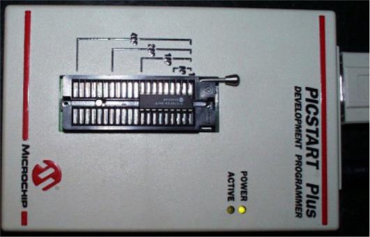
Fig. 16.5 The Microchip PICSTART Plus programmer.
for experimentation, which you are welcome to contribute are given on the associated Web site detailed in the Introduction. Good luck!
474 The Quintessential PIC Microcontroller