


FLEX 6000 Programmable Logic Device Family Data Sheet
Figure 8. LE Clear & Preset Modes
Asynchronous Clear |
|
Asynchronous Preset |
|
|
|
||||||||
|
|
|
|
|
labctrl1 or |
|
|
|
|||||
|
|
|
|
|
labctrl2 |
|
|
|
|
|
|
|
|
|
|
|
D |
Q |
Chip-Wide Reset |
|
|
|
|
|
|
|
|
|
|
|
|
||||||||||
|
|
|
|
|
|
|
|
|
|
|
|
|
|
|
|
|
|
|
|
|
|
|
|
|
|
|
|
|
|
|
|
|
|
|
|
|
|
|
PRN |
|
|
|
|
|
CLRN |
|
|
|
|
|
D |
|
Q |
|
|
|
|
|
|
|
|||||||||
labctrl1 or |
|
|
|
|
|
|
|
|
|
|
|||
labctrl2 |
|
|
|
|
|
|
|
|
|
|
|
|
|
|
|
|
|
|
|
|
|
|
|
|
|||
Chip-Wide Reset |
|
|
|
|
|
|
|
|
|
|
|
|
|
|
|
|
|
|
|
|
|
|
|
|
|||
|
|
|
|
|
|
|
|
|
|
|
|
|
|
|
|
|
|
|
|
|
|
|
|
|
|
|
|
Asynchronous Clear
The flipflop can be cleared by either LABCTRL1 or LABCTRL2.
Asynchronous Preset
An asynchronous preset is implemented with an asynchronous clear. The Altera software provides preset control by using the clear and inverting the input and output of the register. Inversion control is available for the inputs to both LEs and IOEs. Therefore, this technique can be used when a register drives logic or drives a pin.
In addition to the two clear and preset modes, FLEX 6000 devices provide a chip-wide reset pin (DEV_CLRn) that can reset all registers in the device. The option to use this pin is set in the Altera software before compilation. The chip-wide reset overrides all other control signals. Any register with an asynchronous preset will be preset when the chip-wide reset is asserted because of the inversion technique used to implement the asynchronous preset.
The Altera software can use a programmable NOT-gate push-back technique to emulate simultaneous preset and clear or asynchronous load. However, this technique uses an additional three LEs per register.
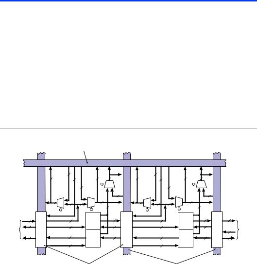
FastTrack Interconnect
In the FLEX 6000 OptiFLEX architecture, connections between LEs and device I/O pins are provided by the FastTrack Interconnect, a series of continuous horizontal and vertical routing channels that traverse the device. This global routing structure provides predictable performance, even for complex designs. In contrast, the segmented routing in FPGAs requires switch matrices to connect a variable number of routing paths, increasing the delays between logic resources and reducing performance.
Altera Corporation |
17 |
FLEX 6000 Programmable Logic Device Family Data Sheet
The FastTrack Interconnect consists of column and row interconnect channels that span the entire device. Each row of LABs is served by a dedicated row interconnect, which routes signals between LABs in the same row, and also routes signals from I/O pins to LABs. Additionally, the local interconnect routes signals between LEs in the same LAB and in adjacent LABs. The column interconnect routes signals between rows and routes signals from I/O pins to rows.
LEs 1 through 5 of an LAB drive the local interconnect to the right, while LEs 6 through 10 drive the local interconnect to the left. The DATA1 and DATA3 inputs of each LE are driven by the local interconnect to the left; DATA2 and DATA4 are driven by the local interconnect to the right. The local interconnect also routes signals from LEs to I/O pins. Figure 9 shows an overview of the FLEX 6000 interconnect architecture. LEs in the first and last columns have drivers on both sides so that all LEs in the LAB can drive I/O pins via the local interconnect.
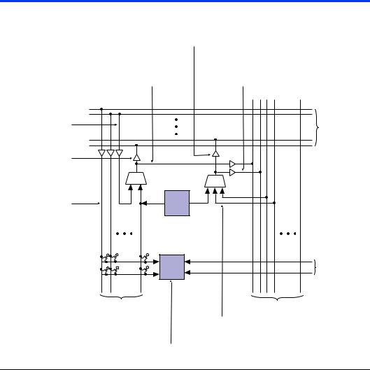
Figure 9. FastTrack Interconnect Architecture
Row Interconnect (n Channels) (1)
|
|
|
2 |
|
|
|
2 |
|
|
|
|
|
|
5 |
|
22 |
5 |
10 |
5 |
22 |
|
5 |
10 |
|
|
|
|
|
|
2 |
|
|
|
2 |
|
|
|
|
|
|
|
|
|
|
20 |
|
|
|
20 |
|
|
|
|
5 |
5 |
5 |
5 |
5 |
5 |
5 |
5 |
|
|
|
|
|
|
10 |
|
|
10 |
|
|
||||
|
|
|
|
|
|
|
|
|
|
|
||
|
5 |
|
10 |
LE 1 |
|
5 |
10 |
|
LE 1 |
5 |
10 |
|
|
|
through |
|
|
through |
|
||||||
To/From |
10 |
|
10 |
|
10 |
10 |
|
10 |
|
|
||
|
LE 5 |
|
|
LE 5 |
|
To/From |
||||||
Adjacent |
|
|
|
|
|
|
|
|
|
|
5 |
Adjacent |
LAB |
10 |
|
5 |
LE 6 |
|
10 |
5 |
|
LE 6 |
10 |
10 |
LAB |
|
|
through |
|
|
through |
|
||||||
|
|
|
|
|
|
|
|
|
|
|
||
|
|
|
10 |
LE 10 |
|
|
10 |
|
LE 10 |
|
|
|
Local Interconnect (32 Channels) |
Column Interconnect (m Channels) (1) |
Note:
(1)For EPF6010A, EPF6016, and EPF6016A devices, n = 144 channels and m = 20 channels; for EPF6024A devices, n = 186 channels and m = 30 channels.
18 |
Altera Corporation |

FLEX 6000 Programmable Logic Device Family Data Sheet
A row channel can be driven by an LE or by one of two column channels. These three signals feed a 3-to-1 multiplexer that connects to six specific row channels. Row channels drive into the local interconnect via multiplexers.
Each column of LABs is served by a dedicated column interconnect. The LEs in an LAB can drive the column interconnect. The LEs in an LAB, a column IOE, or a row interconnect can drive the column interconnect. The column interconnect can then drive another row’s interconnect to route the signals to other LABs in the device. A signal from the column interconnect must be routed to the row interconnect before it can enter an LAB.
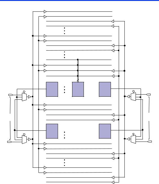
Each LE has a FastTrack Interconnect output and a local output. The FastTrack interconnect output can drive six row and two column lines directly; the local output drives the local interconnect. Each local interconnect channel driven by an LE can drive four row and two column channels. This feature provides additional flexibility, because each LE can drive any of ten row lines and four column lines.
In addition, LEs can drive global control signals. This feature is useful for distributing internally generated clock, asynchronous clear, and asynchronous preset signals. A pin-driven global signal can also drive data signals, which is useful for high-fan-out data signals.
Each LAB drives two groups of local interconnects, which allows an LE to drive two LABs, or 20 LEs, via the local interconnect. The row-to-local multiplexers are used more efficiently, because the multiplexers can now drive two LABs. Figure 10 shows how an LAB connects to row and column interconnects.
Altera Corporation |
19 |
FLEX 6000 Programmable Logic Device Family Data Sheet
Figure 10. LAB Connections to Row & Column Interconnects
Each LE FastTrack Interconnect output can drive six row channels.
At each intersection, four row channels can drive column channels.
Each local channel driven by an LE can drive four row channels.
Row interconnect drives the local interconnect.
Each local channel |
|
driven by an LE can |
Each LE output signal driving |
drive two column |
the FastTrack Interconnect can |
channels. |
drive two column channels. |
|
|
Row |
|
|
Interconnect |
|
LE |
|
|
LE |
From Adjacent |
|
Local Interconnect |
|
|
|
|
Local Interconnect |
|
Column Interconnect |
Any column channel can drive six row channels.
An LE can be driven by any signal from two local interconnect areas.
For improved routability, the row interconnect consists of full-length and half-length channels. The full-length channels connect to all LABs in a row; the half-length channels connect to the LABs in half of the row. In addition to providing a predictable, row-wide interconnect, this architecture provides increased routing resources. Two neighboring LABs can be connected using a half-length channel, which saves the other half of the channel for the other half of the row. One-third of the row channels are half-length channels.
20 |
Altera Corporation |
FLEX 6000 Programmable Logic Device Family Data Sheet
Table 5 summarizes the FastTrack Interconnect resources available in each FLEX 6000 device.
Table 5. FLEX 6000 FastTrack Interconnect Resources
Device |
Rows |
Channels per |
Columns |
Channels per |
|
|
Row |
|
Column |
|
|
|
|
|
EPF6010A |
4 |
144 |
22 |
20 |
|
|
|
|
|
EPF6016 |
6 |
144 |
22 |
20 |
EPF6016A |
|
|
|
|
|
|
|
|
|
EPF6024A |
7 |
186 |
28 |
30 |
|
|
|
|
|
In addition to general-purpose I/O pins, FLEX 6000 devices have four dedicated input pins that provide low-skew signal distribution across the device. These four inputs can be used for global clock and asynchronous clear control signals. These signals are available as control signals for all LEs in the device. The dedicated inputs can also be used as generalpurpose data inputs because they can feed the local interconnect of each LAB in the device. Using dedicated inputs to route data signals provides a fast path for high fan-out signals.
The local interconnect from LABs located at either end of two rows can drive a global control signal. For instance, in an EPF6016 device, LABs C1, D1, C22, and D22 can all drive global control signals. When an LE drives a global control signal, the dedicated input pin that drives that signal cannot be used. Any LE in the device can drive a global control signal by driving the FastTrack Interconnect into the appropriate LAB. To minimize delay, however, the Altera software places the driving LE in the appropriate LAB. The LE-driving-global signal feature is optimized for speed for control signals; regular data signals are better routed on the FastTrack Interconnect and do not receive any advantage from being routed on global signals. This LE-driving-global control signal feature is controlled by the designer and is not used automatically by the Altera software. See Figure 11.
Altera Corporation |
21 |
FLEX 6000 Programmable Logic Device Family Data Sheet
Figure 11. Global Clock & Clear Distribution |
Note (1) |
(2) |
4 |
(3) |
|
|
LAB |
||
LAB C1 |
(Repeated |
||
Across |
|||
|
|||
|
Device) |
||
Dedicated |
|
|
|
Inputs |
|
|
|
(2) |
|
|
|
LAB D1 |
|
|
|
(4) |
LAB C22 |
Dedicated |
Inputs |
(4) |
LAB D22 |
Notes:
(1)The global clock and clear distribution signals are shown for EPF6016 and EPF6016A devices. In EPF6010A devices, LABs in rows B and C drive global signals. In EPF6024A devices, LABs in rows C and E drive global signals.
(2)The local interconnect from LABs C1 and D1 can drive two global control signals on the left side.
(3)Global signals drive into every LAB as clock, asynchronous clear, preset, and data signals.
(4)The local interconnect from LABs C22 and D22 can drive two global control signals on the right side.
22 |
Altera Corporation |