

FLEX 6000 Programmable Logic Device Family Data Sheet
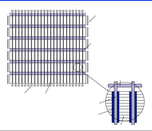
Figure 1. OptiFLEX Architecture Block Diagram
|
IOEs |
|
Row FastTrack |
|
Interconnect |
|
Row FastTrack |
|
Interconnect |
IOEs |
Column FastTrack |
|
Interconnect |
|
Column FastTrack |
|
Interconnect |
Local Interconnect (Each LAB accesses two local interconnect areas.)
Logic Elements
FLEX 6000 devices provide four dedicated, global inputs that drive the control inputs of the flipflops to ensure efficient distribution of highspeed, low-skew control signals. These inputs use dedicated routing channels that provide shorter delays and lower skews than the FastTrack Interconnect. These inputs can also be driven by internal logic, providing an ideal solution for a clock divider or an internally generated asynchronous clear signal that clears many registers in the device. The dedicated global routing structure is built into the device, eliminating the need to create a clock tree.
Logic Array Block
An LAB consists of ten LEs, their associated carry and cascade chains, the LAB control signals, and the LAB local interconnect. The LAB provides the coarse-grained structure of the FLEX 6000 architecture, and facilitates efficient routing with optimum device utilization and high performance.
6 |
Altera Corporation |

FLEX 6000 Programmable Logic Device Family Data Sheet
The interleaved LAB structure—an innovative feature of the FLEX 6000 architecture—allows each LAB to drive two local interconnects. This feature minimizes the use of the FastTrack Interconnect, providing higher performance. An LAB can drive 20 LEs in adjacent LABs via the local interconnect, which maximizes fitting flexibility while minimizing die size. See Figure 2.
Figure 2. Logic Array Block
The row interconnect is bidirectionally connected
Row Interconnect to the local interconnect.
LEs can directly drive the row and column interconnect.
To/From |
|
|
|
|
|
|
|
|
|
|
|
|
|
|
|
|
|
|
|
|
|
|
|
|
|
To/From |
||
|
|
|
|
|
|
|
|
|
|
|
|
|
|
|
|
|
|
|
|
|
|
|
|
|
||||
|
|
|
|
|
|
|
|
|
|
|
|
|
|
|
|
|
|
|
|
|
|
|
|
|
||||
|
|
|
|
|
|
|
|
|
|
|
|
|
|
|
|
|
|
|
|
|
|
|
|
|
||||
|
|
|
|
|
|
|
|
|
|
|
|
|
|
|
|
|
|
|
|
|
|
|
|
|
||||
|
|
|
|
|
|
|
|
|
|
|
|
|
|
|
|
|
|
|
|
|
|
|
|
|
||||
|
|
|
|
|
|
|
|
|
|
|
|
|
|
|
|
|
|
|
|
|
|
|
|
|
||||
|
|
|
|
|
|
|
|
|
|
|
|
|
|
|
|
|
|
|
|
|||||||||
|
|
|
|
|
|
|
|
|
|
|
|
|
|
|
||||||||||||||
Adjacent |
|
|
|
|
|
|
|
|
|
|
|
|
|
|
|
|
|
|
|
|
|
|
|
|
|
|
|
Adjacent |
|
|
|
|
|
|
|
|
|
|
|
|
|
|
|
|
|
|
|
|
|
|
|||||||
LAB or IOEs |
|
|
|
|
|
|
|
|
|
|
|
|
|
|
|
|
|
|
|
|
LAB or IOEs |
|||||||
|
|
|
|
|
|
|
|
|
|
|
|
|
|
|
||||||||||||||
|
|
|
|
|
|
|
|
|
|
|
|
|
|
|
|
|
|
|
|
|
|
|
|
|
|
|
|
|
|
|
|
|
|
|
|
|
|
|
|
|
|
|
|
|
|
|
|
|
|
|
|
|
|
|
|
|
|
|
|
|
|
|
|
|
|
|
|
|
|
|
|
|||||||||||||||
Local Interconnect The 10 LEs in the LAB are driven by two |
|
|
Column Interconnect |
|||||||||||||||||||||||||
|
|
|
|
local interconnect areas. The LAB can drive |
|
|
|
|
|
|
||||||||||||||||||
|
|
|
|
two local interconnect areas. |
|
|
|
|
|
|
||||||||||||||||||
|
|
|
|
|
|
|
|
|
|
|
|
|
|
|
|
|
|
|
|
|
|
|
|
|
|
|
|
|
In most designs, the registers only use global clock and clear signals. However, in some cases, other clock or asynchronous clear signals are needed. In addition, counters may also have synchronous clear or load signals. In a design that uses non-global clock and clear signals, inputs from the first LE in an LAB are re-routed to drive the control signals for that LAB. See Figure 3.
Altera Corporation |
7 |