

FLEX 6000 Programmable Logic Device Family Data Sheet
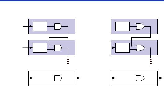
Figure 6. Cascade Chain Operation
AND Cascade Chain |
OR Cascade Chain |
|
LE 2 |
d[3..0] |
LUT |
|
LE 3 |
d[7..4] |
LUT |
LE 2
d[3..0]  LUT
LUT
LE 3
d[7..4] |
|
LUT |
|
|
|
|
|
|
|
|
|
|
|
|
|
|
|
|
|
|
|
|
|
|
|
|
|
|
|
|
|
|
|
|
|
|
|
|
|
|
|
|
|
|
|
|
|
|
|
d[(4n-1)..4(n-1)] |
|
|
|
|
|
|
|
LE n + 1 |
|
d[(4n-1)..4(n-1)] |
|
|
|
|
|
|
|
LE n + 1 |
|
|
||
|
|
|
LUT |
|
|
|
|
|
|
|
|
|
LUT |
|
|
|
|
|
|
|
||
|
|
|
|
|
|
|
|
|
|
|
|
|
|
|
|
|
||||||
|
|
|
|
|
|
|
||||||||||||||||
|
|
|
|
|
|
|
|
|
|
|
|
|
|
|
|
|
|
|
|
|
|
|
|
|
|
|
|
|
|
|
|
|
|
|
|
|
|
|
|
|
|
|
|
|
|
|
|
|
|
|
|
|
|
|
|
|
|
|
|
|
|
|
|
|
|
|
|
|
LE Operating Modes
The FLEX 6000 LE can operate in one of the following three modes:
■Normal mode
■Arithmetic mode
■Counter mode
Each of these modes uses LE resources differently. In each mode, seven available inputs to the LE—the four data inputs from the LAB local interconnect, the feedback from the programmable register, and the carry-in and cascade-in from the previous LE—are directed to different destinations to implement the desired logic function. LAB-wide signals provide clock, asynchronous clear, synchronous clear, and synchronous load control for the register. The Altera software, in conjunction with parameterized functions such as LPM and DesignWare functions, automatically chooses the appropriate mode for common functions such as counters, adders, and multipliers. If required, the designer can also create special-purpose functions to use an LE operating mode for optimal performance.
Figure 7 shows the LE operating modes.
Altera Corporation |
13 |
FLEX 6000 Programmable Logic Device Family Data Sheet
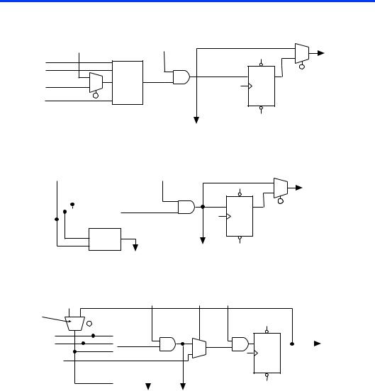
Figure 7. LE Operating Modes
Normal Mode
Carry-In
data1 |
data2 |
data3 |
data4 |
Cascade-In
PRN 4-Input  D Q
D Q
LUT
CLRN
Cascade-Out
Arithmetic Mode
Carry-In |
Cascade-In |
data1 |
|
|
|
3-Input |
data2 |
|
|
|
|
|
|
|
LUT |
|
|
|
|
|
|
|
|
|
|
|
|
|
|
|
|
3-Input LUT
|
PRN |
D |
Q |
CLRN |
|
Cascade-Out
Carry-Out
LE-Out
LE-Out
Counter Mode |
|
|
|
|
|
|
LAB-Wide |
LAB-Wide Synchronous |
|
|||
|
|
|
|
|
|
|
|
Synchronous |
|
|||
Carry-In |
|
|
|
|
Cascade-In |
Load (3) |
Clear (3) |
|
|
|
||
|
|
|
|
|
|
|
|
|
|
|
||
(1) |
|
|
|
|
|
|
|
|
|
|
|
|
|
|
|
|
|
|
|
|
|
|
|
|
|
data1 (2) |
|
|
|
|
|
|
|
|
PRN |
|
||
data2 (2) |
|
|
|
3-Input |
|
|
|
D |
Q |
|
LE-Out |
|
|
|
|
LUT |
|
|
|
|
|||||
|
|
|
|
|
|
|
|
|
|
|
|
|
data3 (data) |
|
|
|
|
|
|
|
|
|
|
|
|
|
|
|
|
|
|
|
|
|
|
|
||
|
|
|
|
|
|
|
|
|
CLRN |
|
||
|
|
|
|
|
3-Input |
|
|
|
|
|
|
|
|
|
|
|
|
LUT |
|
|
|
|
|
|
|
|
|
|
|
|
|
Carry-Out |
Cascade-Out |
|
|
|
|
|
|
|
|
|
|
|
|
|
|
|
|||
Notes:
(1)The register feedback multiplexer is available on LE 2 of each LAB.
(2)The data1 and data2 input signals can supply a clock enable, up or down control, or register feedback signals for all LEs other than the second LE in an LAB.
(3)The LAB-wide synchronous clear and LAB-wide synchronous load affect all registers in an LAB.
14 |
Altera Corporation |

FLEX 6000 Programmable Logic Device Family Data Sheet
Normal Mode
The normal mode is suitable for general logic applications, combinatorial functions, or wide decoding functions that can take advantage of a cascade chain. In normal mode, four data inputs from the LAB local interconnect and the carry-in are inputs to a 4-input LUT. The Altera software automatically selects the carry-in or the DATA3 signal as one of the inputs to the LUT. The LUT output can be combined with the cascadein signal to form a cascade chain through the cascade-out signal.
Arithmetic Mode
The arithmetic mode is ideal for implementing adders, accumulators, and comparators. An LE in arithmetic mode uses two 3-input LUTs. One LUT computes a 3-input function; the other generates a carry output. As shown in Figure 7, the first LUT uses the carry-in signal and two data inputs from the LAB local interconnect to generate a combinatorial or registered output. For example, when implementing an adder, this output is the sum of three signals: DATA1, DATA2, and carry-in. The second LUT uses the same three signals to generate a carry-out signal, thereby creating a carry chain. The arithmetic mode also supports simultaneous use of the cascade chain.
The Altera software implements logic functions to use the arithmetic mode automatically where appropriate; the designer does not have to decide how the carry chain will be used.
Counter Mode
The counter mode offers counter enable, synchronous up/down control, synchronous clear, and synchronous load options. The counter enable and synchronous up/down control signals are generated from the data inputs of the LAB local interconnect. The synchronous clear and synchronous load options are LAB-wide signals that affect all registers in the LAB. Consequently, if any of the LEs in a LAB use counter mode, other LEs in that LAB must be used as part of the same counter or be used for a combinatorial function. In addition, the Altera software automatically places registers that are not in the counter into other LABs.
The counter mode uses two 3-input LUTs: one generates the counter data and the other generates the fast carry bit. A 2-to-1 multiplexer provides synchronous loading, and another AND gate provides synchronous clearing. If the cascade function is used by an LE in counter mode, the synchronous clear or load will override any signal carried on the cascade chain. The synchronous clear overrides the synchronous load.
Altera Corporation |
15 |